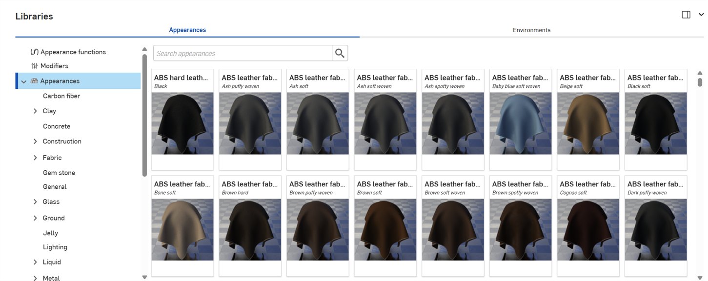
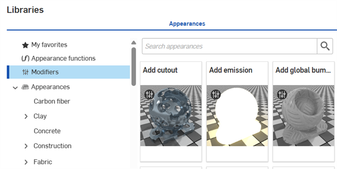
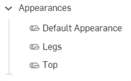
Render Studio 介面 -「Appearances」資源庫
![]()
僅為 提供
位在頁面的下方,「外觀資源庫」中包含所有各種標準屬性的組合,可以套用至零件、零件面或曲面上來提供材料紋理,並有可套用至外觀參數的函式:
Search
使用「Search appearances」欄位來縮小在資源庫中對外觀的搜尋結果。「Search appearances」欄位會僅找出在所選資料夾內的外觀。例如,在上方的圖片中選取了 Ceramic 資料夾,在「Search appearances」欄位中輸入關鍵字然後按下 Enter 鍵,系統僅會顯示在 Ceramic 資料夾中的結果。
在字詞之間使用 "and"、"+"、與 "or" 運算子來進一步縮小搜尋範圍。
在縮小搜尋範圍之後,結果會以縮圖清單顯示在「外觀」面板的右側。若要清除搜尋,刪除在「Search appearances」欄位中的關鍵字,然後按下 Enter 鍵或按下清除欄位圖示 (![]() )。
)。
在水平與垂直資源庫檢視中切換
按一下面板右上角的 Show library in the right panel 圖示來在右側面板中顯示資源庫:
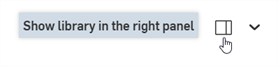
按一下資源庫面板圖示 (![]() ) 來關閉面板。再次點按即可開啟。
) 來關閉面板。再次點按即可開啟。
若要將資源庫放回到其預設的水平位置,按一下面板右上角的 Show library in the bottom panel 按鈕 (上圖中以紅色強調顯示i)。
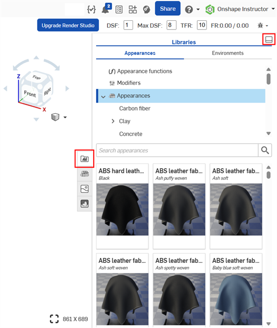
若要將一個外觀函式拖曳到右側面板的「Appearances」資源庫的外觀參數上,請將外觀函式拖曳到「Appearances」面板圖示上,按住直到面板開啟。接著將外觀函式放置在面板中的參數上。詳細資訊請參考使用外觀函式。
將「Bump map」外觀函式拖曳到「 Appearance」面板圖示上 (左圖)。「 Appearance」面板開啟 (中間圖)。在按住的同時,將「Bump map」外觀函式拖曳到「 Appearance」面板中的「Bumps」參數上 (右圖)。
隱藏/顯示資源庫
若要隱藏/顯示資源庫面板,請按一下面板右上角的展開/摺疊切換 (![]() )。
)。
檢視外觀名稱
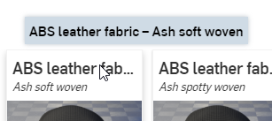
如果沒有顯示外觀的整個名稱,請移動游標至名稱上暫留,工具提示會顯示完整的名稱:
檢視外觀說明
按一下外觀卡底部的「View description」切換 (![]() ) (下方左上圖) 來將卡片翻面以顯示卡片背面的外觀簡短說明 (下方右上圖)。如果說明過長卡片無法容納,請將游標移動至文字上暫留一下,卡片即會展開以顯示完整的說明 (下方底部圖片)。再次點按「View description」切換 來將卡片翻回正面的縮圖。
) (下方左上圖) 來將卡片翻面以顯示卡片背面的外觀簡短說明 (下方右上圖)。如果說明過長卡片無法容納,請將游標移動至文字上暫留一下,卡片即會展開以顯示完整的說明 (下方底部圖片)。再次點按「View description」切換 來將卡片翻回正面的縮圖。
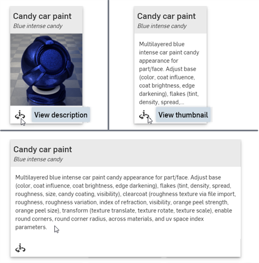
一次只能將一個外觀卡翻到背面的說明。按一下第二個外觀的「View description」切換會同時將第一個外觀的說明圖翻回正面 (縮圖),並將第二個外觀的視圖翻到背面 (說明)。
關於所有外觀與外觀函式的完整清單,請參考 Render Studio 資源庫。
關於預設外觀參數的說明,請參考外觀面板。
提示
-
如果無法將外觀指派給一個零件 (使用拖放來將外觀套用至零件上時沒有提供環境選單選項或是沒有顯示),這可能表示外觀是一個函式。必須在「外觀」面板中套用外觀參數 (藉由拖曳與放置)。詳細資訊請參考使用外觀函式。
-
在將外觀套用至零件、Part Studio 或組合件之後,檢查「外觀」面板並瀏覽檢閱外觀的子功能表。這個面板中包含對目前外觀所有可編輯的參數。
-
如果「外觀」面板是空白的,極有可能是在「Scene list」或圖形區域中選擇了多個項目。取消選取除了一個項目之外的所有項目,「Appearance」面板應會填入適用的參數。
-
如果外觀是一個光源 (加入散射、漫射光、光度光源、聚光燈),請確定有建構一些牆面或其他零件可讓光源得以進行具體反射。如果光源是黑色的,請在「外觀」面板中增加「強度」和/或「單位比例」參數。詳細資訊請參考光源散射。
-
如果外觀中包含並未出現在零件上的圖案或紋理,有可能是圖案或紋理太小或太大。在「外觀」面板中增加或減少「縮放」參數。此外,也可嘗試增加「強度」參數 (如果有的話)。
-
若要調整「Appearances/Environments」資源庫面板的高度,請將游標移動至面板邊緣暫留,當游標變為雙邊箭頭時,按一下並拖曳來重新調整面板的大小。
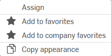
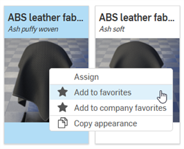
在「Appearances」資源庫中的外觀縮圖上按右鍵,會顯示有下列選項的環境選單:
在將外觀指定給圖元時,也會將這個外觀指定給「Scene list」中下方沒有指定明確外觀的所有圖元。例如,將金屬外觀指定給「Scene list」中的組合件時,也會將相同的金屬外觀指定給組合件下方沒有指派明確外觀的所有圖元。
在將外觀指定給零件時,若其下的面已經有指定的外觀,系統會顯示下列的對話方塊:

按一下 Clear face appearances 連結來移除零件其下面的所有指定外觀,並將新指定的外觀套用至整個零件上。
系統會將這個程序視為兩個 2 不同的復原步驟:
-
從所有零件面清除 (移除) 外觀
-
將新的外觀指定給零件 (以及零件所有的面)。
如果您改按 x 來關閉訊息,則已經有指定外觀的零件面會保留原先外觀,零件外觀只會套用到零件與沒有指定外觀的所有零件面上。
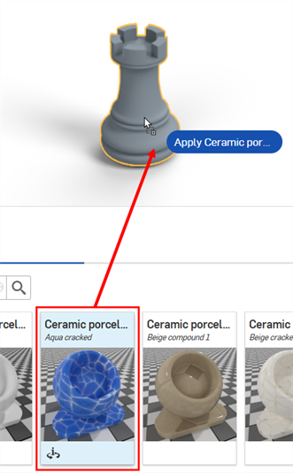
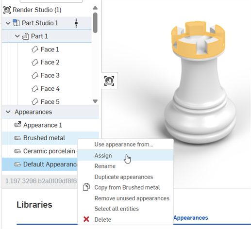
在下方的範例中,已將拉絲金屬外觀指定給西洋象棋車 (Rook) 模型的外冠面上。接著又將藍色的陶瓷外觀指定給整個 Rook 零件。按下 x 來關閉「Clear face appearances」訊息會將藍色陶瓷外觀套用到除了外冠面的所有零件面上,外冠面會保留拉絲的金屬外觀 (下圖左側所示)。或者,按下 Clear face Appearances 連結則會從外冠面清除(移除) 拉絲金屬外觀,再將藍色陶瓷外觀套用至零件 (與其下所有的零件面) 上 (下圖右側所示):
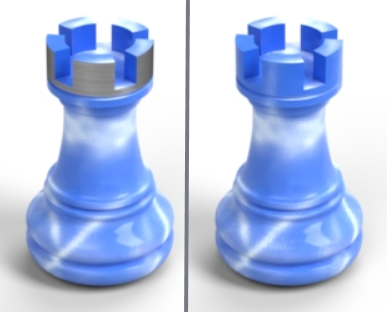
沒有清除面外觀 (左圖),清除了面外觀 (右圖)
有 6 種方法可將外觀指定給場景圖元 (Render Studio、Part Studio、組合件、零件或面)。請執行下列方法之一:
若要將一個外觀套用到多個「Scene list」中的圖元上,請在「Scene list」或圖形區域中預先選取圖元。將外觀指定或拖放到其中一個所選圖元上,則系統會將外觀指定給所有的圖元。
如果拖曳一個外觀,可以將其放置在一個零件而非面上。若要將外觀指定給一或多個面,請先選擇面,然後在「Appearances」資源庫中的外觀上按右鍵,再從環境選單中選擇 [Assign]。另一種方式是將外觀拖放到「Scene list」中的一或多個面上。
某些外觀是函式,某些函式無法使用下列所述的方法來加入。詳細資訊請參考使用外觀函式。
-
將外觀從「Appearances」資源庫拖放到圖形區域中的選取零件上。您僅能使用這個方法來將外觀套用到零件上而不是面上。
-
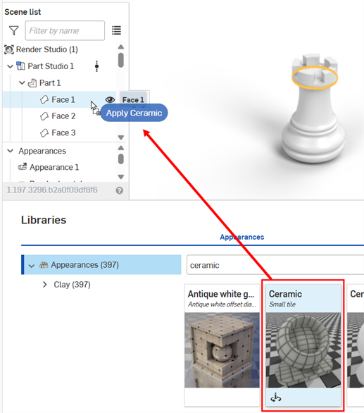
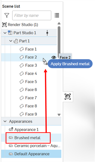
將外觀從「Appearances」資源庫拖放到「Scene list」中選取的圖元上。使用這個方法您可以將外觀套用到 Render Studio、Part Studio、組合件、零件或面上:
-
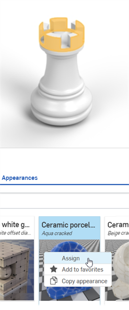
在「Scene list」或圖形區域中選擇圖元,然後在「Appearances」資源庫中的外觀上按右鍵,接著從環境選擇單中選擇 Assign:
-
如果您要指定的外觀已經存在於「Scene list」中 (在「Appearances」清單之下),可直接將這個外觀拖放到圖形區域中的零上。您僅能使用這個方法來將外觀套用到零件上而不是面上。
-
如果您要指定的外觀已經存在於「Scene list」中 (在「Appearances」清單之下),請在「Scene list」或圖形區域中選擇圖元,然後在外觀上按右鍵,接著在環境選單中按一下指派:
-
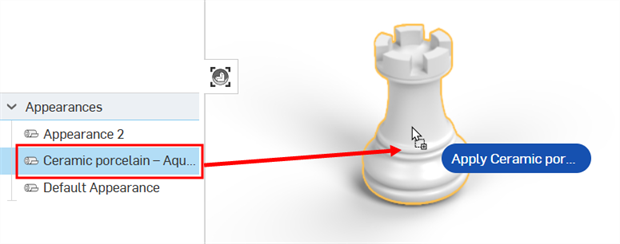
如果您要指定的外觀已經存在於「Scene list」中 (在「Appearances」清單之下),請在「Scene list」或圖形區域中選擇圖元,然後將外觀從「外觀」清單直接拖放到「Scene list」中的選取圖元上:
若要從零件或面上移除外觀,請執行下列操作之一:
-
在「Scene list」中選擇一或多個零件或是面,然後按右鍵並從「Scene list」環境選單中選擇 Unassign appearance :
![從「Scene list」環境選單中選擇 [Unassign appearance]](Resources/Images/render-studio/remove-appearance-01-06.png)
-
在圖形區域的零件或零件面上按右鍵,然後從環境選單中選擇 Unassign appearance。使用這個方法時,一次只能移除一個零件或面的外觀:
![從圖形區域環境選單中選擇 [Unassign appearance]](Resources/Images/render-studio/remove-appearance-08-03.png)
可以從下列的位置複製外觀。在所有情況中,按右鍵並從環境選單中選擇 Copy Appearance:
-
「Appearance」資源庫中的外觀
-
「Appearance」清單中的外觀 (在「Scene list」之下)。
-
圖形區域中的零件或面
一旦外觀在出現在剪貼簿中,可以把它貼到:
-
在圖形區域中的一或多個零件或面上。在強調顯示的圖元 (零件或面) 上按右鍵,然後選擇 Paste Appearance on entity。如果選取了多個圖元,您可以使用相同的環境選單選項來將外觀貼到多個圖元上。
-
「Scene list」中的圖元。只能將外觀貼到一個圖元上。並不支援貼到「Scene list」中的多個圖元中。不過,您可以貼到最上層的 Render Studio 上,這樣會將外觀指定給場景中的所有圖元。
-
「Appearances」清單 (在「Scene list」之下) 中的一個外觀。在外觀上按右鍵,然後選擇 Paste Appearance on [Appearance]
或者,與其使用環境選單來複製/貼上,您可以用下列的方式來拖曳及置放外觀:
-
從「Appearances」資源庫拖放到圖形區域中的一或多個零件上。您僅能使用這個方法來將外觀套用到零件上而不是面上。
-
從「Appearance」資源庫到拖放到「Scene list」中的一個圖元 (Render Studio、Part Studio、組合件、零件或面)。
-
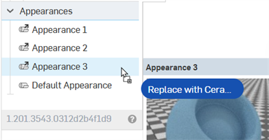
從「Appearances」資源庫拖放到「Appearances」清單中的一個外觀上。執行這樣的操作時,在「Appearances」清單中的外觀會被拖曳於其上的外觀取代。在「Scene list」中使用被取代外觀的所有元素現在會使用新的外觀。
-
從「Appearances」清單中的外觀拖放到「Scene list」中的一個圖元 (Render Studio、Part Studio、組合件、零件或面)。
-
從「Appearances」清單中的一個外觀拖放到「Appearances」清單中的另一個外觀上。執行這樣的操作時,在「Appearances」清單中的外觀會被拖曳於其上的外觀取代。在「Scene list」中使用被取代外觀的所有元素現在會使用新的外觀。
-
從「Appearances」清單拖放到圖形區域中的一或多個零件上。您僅能使用這個方法來將外觀套用到零件上而不是面上。
您也可以使用 ctrl/cmd+c 來複製外觀,並使用 ctrl/cmd+v 來貼上外觀,前提是您的游標是在可允許這樣操作的正確位置上。例如,移動游標在「外觀」資源庫中的外觀上暫留可以複製,移動游標在圖形區域中的選取面或零件上暫留可以貼上。
注意事項:
-
複製和貼上外觀使用跟加入外觀相同的邏輯。請參考將外觀加入至「Scene list」圖元。
-
如果之前沒有重新命名目標外觀,系統會使用來源外觀的名稱。如果之前已重新命名目標外觀,則在將來源外觀取代目標外觀時,系統會保留這個名稱。
-
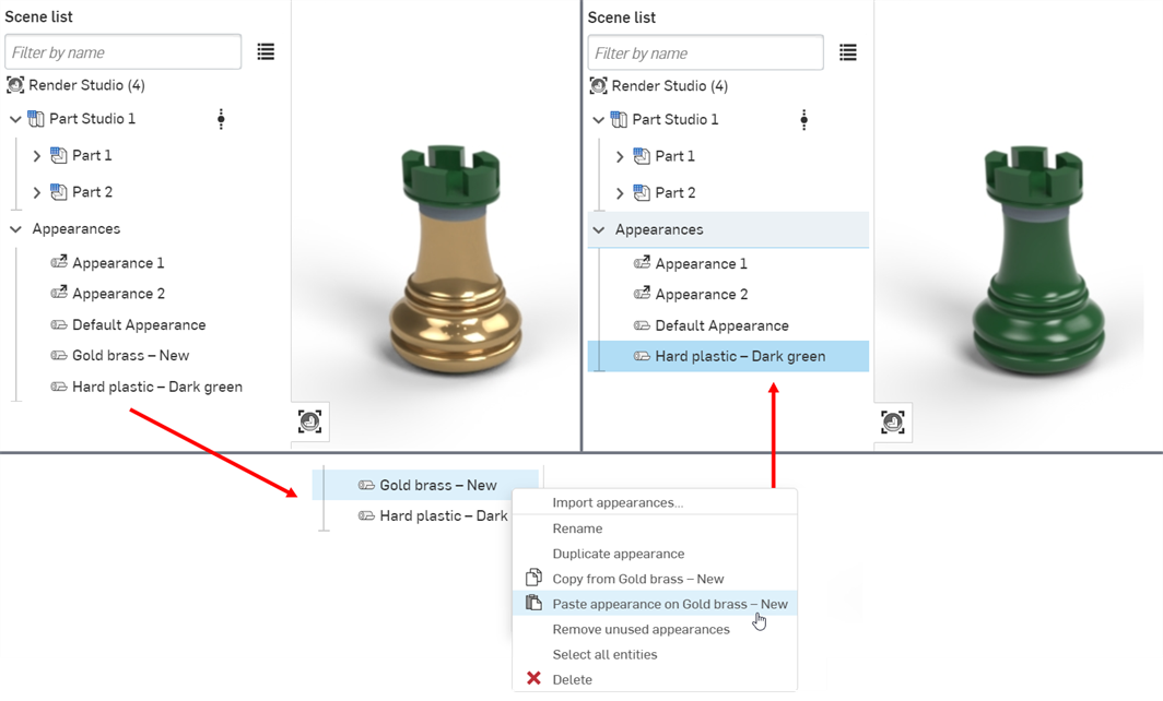
從「Appearances」清單複製一個外觀 (來源) 並將其貼到「Appearances」清單中的另一個外觀上 (目標) 會取代目標外觀,並將其從「Appearances」清單中移除。之前指定使用目標外觀的所有圖元現在會改用來源外觀。
例如,在下方的圖片中,將 Hard plastic — Dark green 外觀複製並貼到 Gold brass — New 外觀上。這樣會從「Appearances 」清單中移除 Gold brass — New 外觀,任何先前指定使用 Gold brass — New 外觀的圖元現在會改用 Hard plastic — Dark green 外觀。
-
如果貼到連結的外觀上,則連結會斷開,新的外觀會取代連結的外觀。
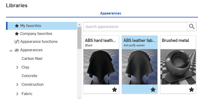
任何使用者都可以將外觀加入至 My favorites 資料夾中。如果您是在公司 (Professional 計畫) 或企業 (Enterprise 計畫) 中且有編輯公司最愛的所需權限,您可以將任何外觀加入至 Company favorites 資料夾ˊ中。這兩個資料夾都可幫助您分類並快速存取常用的外觀。
如果其中沒有任何外觀,就不會看到這兩個資料夾。根據預設,您不會看到這兩個資料夾列在「Appearance」資源庫的資料夾清單中。
一個外觀可以同時放置在這兩個資料夾中。
將外觀加入至 My favorites 或 Company favorites 資料夾中:
-
找出您要加入到 My favorites 或 Company favorites 資料夾中的外觀。
-
在外觀上按右鍵,然後選擇 Add to favorites 或 Add to company favorites:
-
外觀現在會位在「Appearance」資源庫的資料夾清單最上方的 My favorites 或 Company favorites 資料夾中。最愛的外觀在其縮圖右下角會顯示一個星號圖示 (
 )。
)。
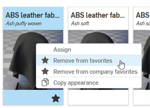
若要從最愛資料夾中移除一個外觀,在外觀上按右鍵,然後選擇 Remove from favorites 或 Remove from company favorites:
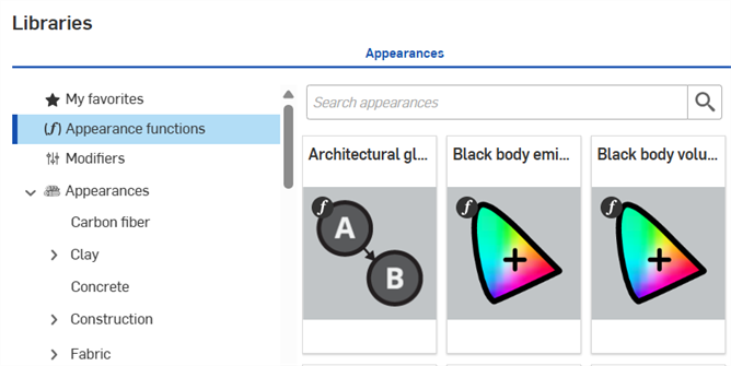
函式是各種特別類型的外觀,可在零件的外觀參數上執行特定的操作。在建立場景時,每個零件會有預設的外觀參數組,可在右側的參數面板中檢視這些參數。
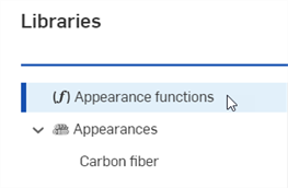
所有的函式都位在最上層的 Appearance functions 資料夾中。此外,系統會在外觀縮圖左上角以函式圖示 (![]() ) 來表示函式:
) 來表示函式:
提示
-
某些函式無法直接將指定給零件。如果無法在外觀縮圖上使用按右鍵環境選單選項,或是在將外觀縮圖拖放到場景中零件上時沒有開啟任何環境選單,則表示外觀是一個函式。
-
關於所有函式的完整清單與各函式的簡短說明,請參考「Appearance」資源庫 - 函式。
-
只能將某些函式套用至「選取項目」面板中的參數上,並取決於在「Scene list」中所選的項目為何。
-
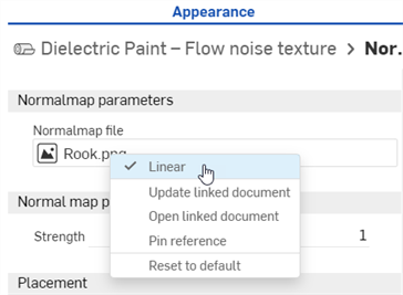
對於「Normal map — texture」函式,可以選擇性地將紋理資源視為包含線性色彩的資料。當紋理代表色彩之外的事項時 (例如相切空間法線貼圖或像是粗糙度等純量資料),則應將其視為線性,以確保正確處理色彩的資料。
特別針對法線貼圖紋理,系統會自動選取「Linear」選項以確保有效的結果。對於其他參數,您可以使用紋理資源環境選單上的「Linear」選項來選擇要解讀色彩的方式 (請見下方):
-
若要將一個外觀函式套用到右側面板的「Appearances」資源庫的外觀參數上,請將外觀函式拖曳到「Appearances」面板圖示上,按住直到面板開啟。接著將外觀函式放置在面板中的參數上。
將「Bump map」外觀函式拖曳到「 Appearance」面板圖示上 (左圖)。「 Appearance」面板開啟 (中間圖)。在按住的同時,將「Bump map」外觀函式拖曳到「 Appearance」面板中的「Bumps」參數上 (右圖)。
套用函式至零件的外觀參數上:
-
在「Scene list」或圖形區域中選擇零件。「Appearance」面板會顯示零件的預設外觀參數。
-
在外觀「資源庫」中選擇 Appearance functions 資料夾
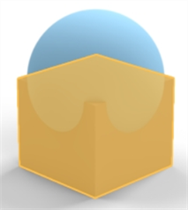
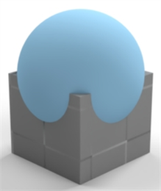
找出 Checker pattern — 3D texture 與 Checker texture bump map 函式。在這個範例中同時使用這兩個函式。將使用下方模型中底部的方塊來做為參考:
-
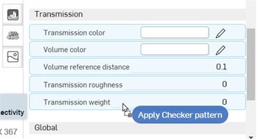
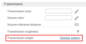
將 Checker pattern — 3D texture 函式拖曳至「外觀」面板中。在放下之前,注意到系統以藍色強調顯示許多的外觀參數。這表示可以將函式套用到任何的這些參數上。函式是套用至滑鼠游標之下的參數。將函式放置在 Transmission 子功能表中的 Transmission weight 參數上:
-
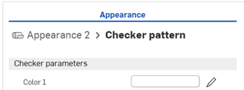
系統隨即套用紋理函式並自動在「外觀」面板中開啟它。可以檢視「外觀」面板最上方的階層式導覽路徑來確認 (下方中第一個圖片所示)。點按這個導覽路徑中的 Appearance 2 連結,會開啟零件的外觀,其中在Transmission weight 參數旁會顯示對紋理函式的連結 (下方中第二個圖片所示)。
-
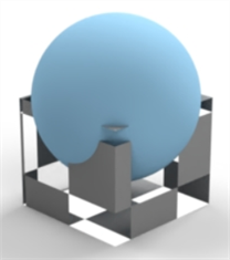
這個紋理函式就像是可讓光線穿透零件的遮罩 (checker texture 是套用至零件外觀 Transmission weight 參數上的函式)。在方格圖案為白色的任意處會顯示光線的穿透,在方格圖案為黑色的任意處則會穿透顯示基材零件的色彩。方格圖案是零件的光穿透遮罩:
-
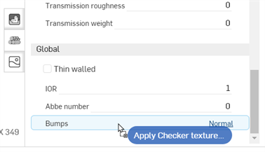
或者也可以將 Checker texture bump 函式外觀放置在「外觀」面板中「Global」子功能表內的 Bumps 參數上。 Bumps 參數是唯一個變為藍色的,表示這是唯一接受 Checker texture bump map 函式的參數:
-
Checker texture bump map 函式套用到 Bumps 參數上,如下所示:
下一個範例將套用 Invert color (反轉色彩) 函式到零件的基準色彩上。可將這個方法套用至任何外觀色彩參數上,並可用來對換色彩。
-
選擇零件。在這個範例中選取的是球體。
-
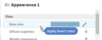
將 Invert color 函式拖放到「外觀」面板中零件 Base 子功能表內的 Base color 上:
-
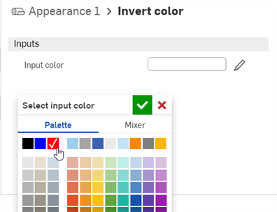
Invert color 函式會在「外觀」面板之下開啟。按一下「Input color」並選擇一個色彩。會在零件基準色彩中使用該顏色的反色。在下列的範例中,選擇紅色會建立一個青色的基準色彩,因為青色是紅色的反色:
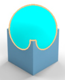
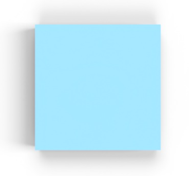
這個範例使用 Surface blender 函式來將兩個表面外觀混合。在完成之後,再將另一個函式 (Gradient3-color/position texture) 套用到第一個函式的參數上 (Surface blender 的「Blend weight」)。這個範例展示如何建構基於另一函式的函式。
-
在「Scene list」中選擇零件。在這個範例中選取了一個正方形方塊,並是從 top (上) 平面來檢視的。供您參考之用,方塊的尺寸是 .5 米長 x .5 米寬 x .5 米高:
-
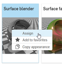
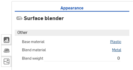
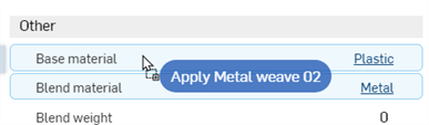
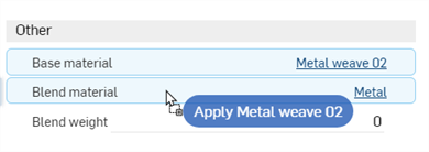
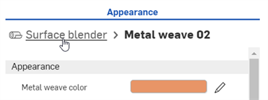
在「外觀」資源庫中篩選找出Surface。在 Surface blender 縮圖上按右鍵然後按一下指派 (下方中第一個圖片所示)。「外觀」面板中的「Global」子功能表會顯示 Surface blender 函式的參數 (下方中第二個圖片):
-
Base material - 混合所基於的外觀。
-
Blend material - 混合外觀表面性質。
-
Blend weight - 混合權重或遮罩紋理。
-
-
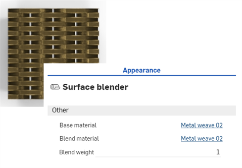
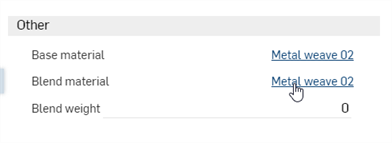
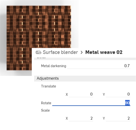
搜尋找出 Metal weave 02 - brass steel 外觀並將縮圖拖放至「Base material」參數上 (下方中第一個圖片所示)。接著搜尋找出 Metal weave 02 - copper pure 外觀並將縮圖拖放至「Blend material」參數上 (下方中第二個圖片所示)。將「Blend weight」調整為 1。這樣會混合兩種外觀 (Base material 與 Blend material) 的顏色。下方中的第三個圖片顯示所產生的結果:
-
按一下混合材料的連結來在「外觀」面板中開啟其參數 (下方中第一個圖片所示)。在「Adjustments」子功能表中將材料旋轉 90 度。水平的圖案現在是與新旋轉的垂直圖案結合在一起 (下方中第二個圖片所示)。這樣可更好地視覺呈現兩者之間的混合:
-
若要回到父 Surface blender 的層級,按一下「外觀」面板最上方的階層式導覽路徑內的 Surface blender 連結:
上方的步驟適用於將任何兩種表面外觀混合在一起。在上方的操作之後,將漸層函式套用至 Surface blender 函式的「混合權重」參數上來混合兩種外觀。
-
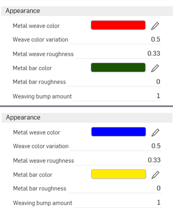
開啟 2 個外觀並將其編織與金屬條的色彩變更如下:將 Base material 分別改為紅色與綠色,Blend material 則改為藍色與黃色。這樣在下一個步驟中可更清楚的看到混合。結果顯示在下方的第二個圖片中:
-
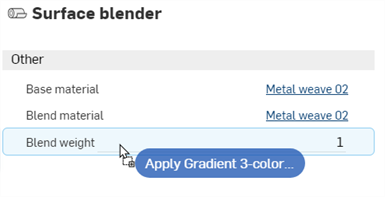
回到父 Surface blender 層級中,在「外觀」資源庫中找出 Gradient 3-color/position texture 函式,然後將縮圖拖放到「Blend weight」參數上。
-
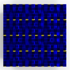
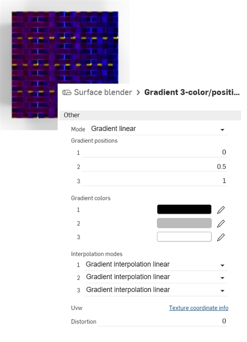
現在已將 Gradient 3-color/position texture 函式套用到 Surface blender 函式參數的「Blend weight」上。會將漸層用做為紅與綠色 Base material (在左邊開始) 與藍與黃色 Blend material (在右邊結束) 間的遮罩。在漸層是黑色的地方,Base material 會穿透顯示。在漸層是白色的地方,Blend material 會穿透顯示。
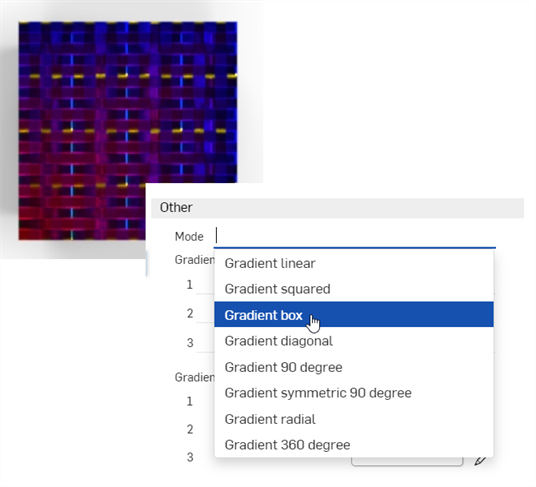
修改「Gradient」參數會產生兩個混合外觀之間的各種漸層結果變化。例如,下方圖片顯示的是 Mode: Gradient box 選項 (下方中第二個圖片所示):
提示
-
若要混合兩種顏色,請使用 Blend colors 函式,並將其套用在「外觀」或「選取項目」面板中任何可用的色彩參數上。使用 Blend colors 函式可開啟對像是 Adobe Photoshop 與 GIMP 等應用程式中的圖層混合模式 (變暗、濾色、色彩增值與其他功能) 的存取。
-
若要在兩個凹凸紋理間進行混合,請使用 Blend normals 函式,並將其套用在「外觀」或「選取項目」面板中任何可用的「凹凸」參數上。
-
改用 Gradient 3-color/position texture 函式之外的其他紋理函式,像是 Checker pattern 或 Bump map — Perlin noise texture 來混合兩個外觀。
-
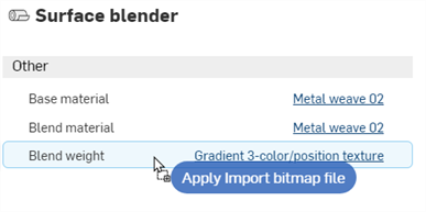
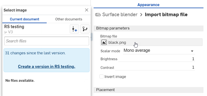
加入自訂紋理以混合兩個外觀。將 Import bitmap file 函示拖放到「Blend weight」參數上 (下方中第一個圖片所示),然後按一下「Bitmap file」來開啟「選擇影像」對話方塊,您可於其中載入自訂的紋理 (下方中第二個圖片所示):
關於混合的技術性提示,請參考在 Render Studio 中使用紋理與混合。
這個程序說明如何將特定的體積與體積係數函式加入至場景中的零件上。體積會以外觀的方式加入零件中,而體積係數則是加入至外觀吸收係數參數的函式。
在這個範例中有一個置於水下場景的發光船體物件,水用做為體積。
-
若要加入體積,場景必須是由體積包圍住的。請建構一個在各邊環繞船體物件的零件,並必須夠大以提供足夠的空間。
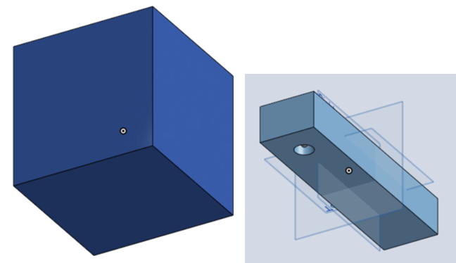
提供一些訊息供您參考。在這個範例中的環繞方盒是 5 米的立方體。 矩形「船體」的尺寸是 0.6 米長、0.075 米寬與 0.05 米高。矩形底部前方有一個直徑為 0.025 米,深度為 0.03 米的鑽孔,因此並未完全貫穿矩形。最後在孔內有一個半徑 0.004 米的球體做為光源之用。這些圖元 (零件) 在下方分別以體積、船體及光源來表示。
-
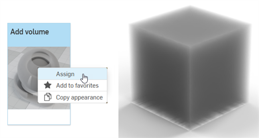
在「Scene list」中選擇 volume 零件。在「Appearance」資源庫中搜尋 volume,在「Add volume」縮圖上按右鍵,然後從環境選單中選擇 Assign。這樣會在零件周圍套用厚重的體積外觀。
-
Base material - 套用體積於其上的材料,預設是透明的。
-
Absorption coefficient - 光源被參與介質吸收的機率密度 (世界空間中每米)。預設為白色 (R: 255; G: 255; B: 255)。較高的吸收值會使得介質較暗,因為更多光線穿過介質時會被吸收。
-
Scattering coefficient - 光源從其目前方向散射的機率密度 (世界空間中每米)。預設是白色 (R: 255; G: 255; B: 255)。較高的散射值射會分配更多光線穿過介質。
-
Directional bias - 散射時光源方向的影響程度。0 的值表示等向性散射,1 則是前向散射,−1 是反向散射。預設值是 0。
-
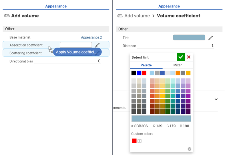
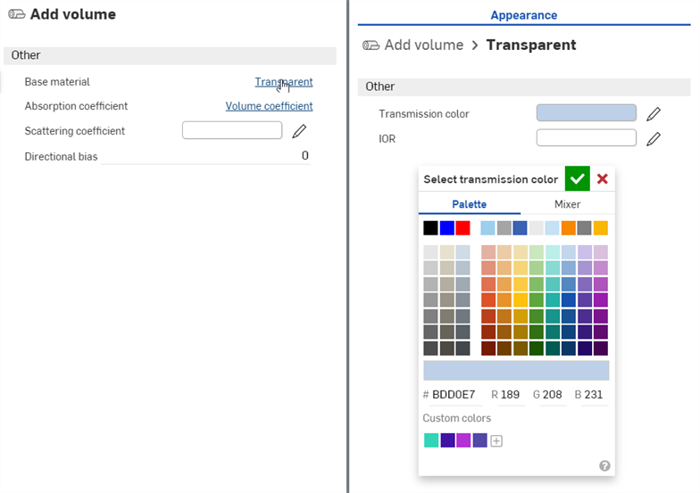
在「外觀」資源庫 > Appearance functions 資料夾中找出並拖放 Volume coefficient 函式到「外觀」面板中的「Absorption coefficient」參數上 (下圖左側所示)。然後將「Tint」參數調整為 R:139;G:179;B:198 (下圖右側所示)。這樣會增加包住船體的水量。
-
按一下「Base Material」參數旁的 Transparent 連結,然後如下所示將「Transmission color」調整為 R:189;G:208;B:231:
-
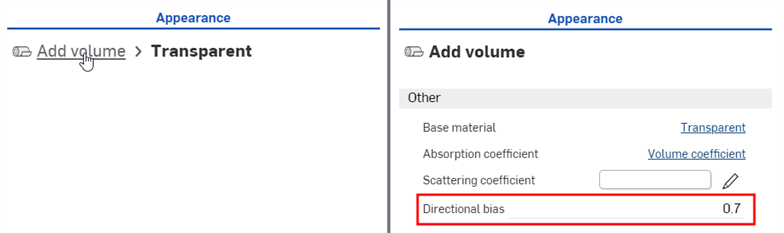
按一下「外觀」面板上方的 Add volume 連結來回到體積參數中。將「Directional bias」設定 0.7。這樣可照亮場景來看到水中的船體。
-
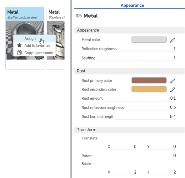
在「Scene list」中,取消選取 volume 零件並選擇 ship 零件。在「Appearance」資源庫中找出 Metal — Scuffed oxidized steel 外觀,在縮圖上按右鍵再從環境選單中選擇指派 (下圖左側所示)。在「外觀」面板中調整下列的參數:Scale:X: 2、Y: 2;Rust bump strength:0.4;Rust amount:0.1;Rust reflection roughness:0.5;Reflection roughness:1:
-
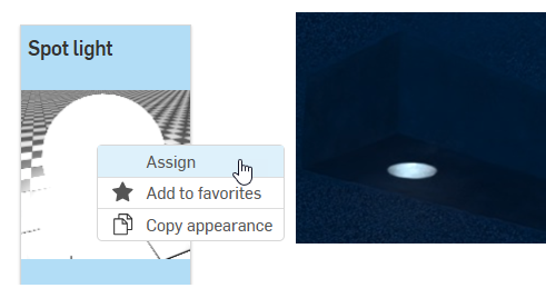
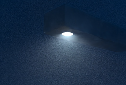
在「Scene list」中取消選取 ship 零件,然後選擇 light 零件。在「Appearance」資源庫中找出 Spot light 外觀,在縮圖上按右鍵再從環境選單中選擇指派 (下圖左側所示)。放大船體以從下方往上檢視。會有照亮的光源但是非常微弱 (下圖右側所示):
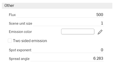
Spot light 的參數如下:
-
Emission color - 光源的顏色。會經過重新調整所以不會影響到光通量。預設是白色 (R: 255; G: 255; B: 255)。
-
Flux - 光源散發的總光通量 (以流明為單位)。預設值是 500。取決於場景,通常會需要增加這個值。
-
Scene unit size - 將米轉換為場景單位。例如,如果 1 在場景中是一英呎 (美國慣用單位),則場景的單位大小會是 0.30481。預設值是 1。
-
Spot exponent - 指數越高,光的發射就越聚焦。預設值是 0。
-
Spread angle - 以 RAD 為單位的擴散角度。聚光擴散的固定限制。預設值是 6.283。
-
Two sided emission - 如果啟用的話,會同時在幾何的正面與背面發射。預設是停用的。
-
-
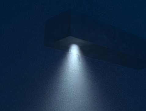
將「Flux」設定 20000,「Scene unit size」設定為 0.8。光源現在會發射出更強的光線,且是漫射與不聚焦的:
-
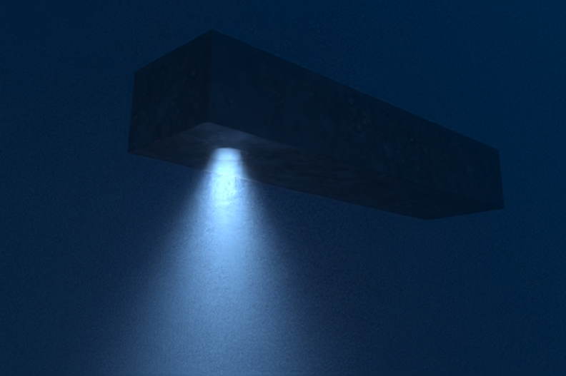
若要將光線聚集在較窄的樑上,請將「Spot exponent」設定為 15,「Spread angle」設定為 2.5:
-
將光的顏色與水混合,修改「Emission color」為 R: 157;G: 189;B: 226。請記住,可以將任何的這些參數調整至不同的規格。這個範例是渲染場景影像的變化之一:
下方概述「Add volume」外觀面板的參數:
修飾器是用來修改其他外觀的某一特殊外觀類型。將修飾外觀拖曳並放置在場景中的零件或面上,或將其拖曳並置放在面板中的「外觀」參數上。這些修飾器並不會覆寫先前的外觀,修飾器是與新修飾外觀的 Base material 參數相關聯的。
若要改用新的修飾外觀來覆寫先前的外觀,請在「Scene list」或圖形區域中選擇零件或零件面,接著在外觀資源庫中的修飾外觀縮圖上按右鍵,然後從環境選單中選擇 [指派]。
所有修飾器都是位在最上層的「Modifiers」資料夾ˊ中。此外,修飾器會以在外觀縮圖左上角的修飾器圖示 (![]() ) 表示:
) 表示:
變換外觀與變換零件類似;不過,只有外觀可以變換,零件是維持為靜態的。這個範例使用一個木頭桌子,將變換木頭外觀來讓桌子看起來更逼真。
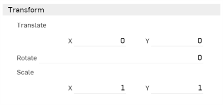
外觀通常在「外觀」面板中有一個「transform」子功能表,其中有「Scale」與「Translate」的 x 和 y 軸值,「Rotation」的度數值,如下所示:
-
Translation - 根據選取項目的原點沿著 x 和 y 軸移動選取的項目。測量的單位是米,可以是負數或正數。
-
Rotation - 繞選取項目 z 軸的中心點旋轉紋理的角度,可以從 -360 到 +360 度。
-
Scale - 根據選取項目的中心點沿 x 與 y 軸放大 (更大) 或縮小 (較小) 選取的項目。測量是根據選取項目的原始大小。例如,1.000 x 與 1.000 y 的比例表示縮放是零件原始大小 100%。從 0.001 到 1 的分數值會降低所選項目的大小。
-
建立一個有桌面與四支桌腳的組合件,所以一共有五個組裝零件。
-
建立一個 Render Studio 場景並插入桌子 (table) 組合件。
-
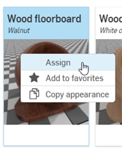
在「Scene list」中選擇「table top」。在「Appearance」資源庫中搜尋 Floorboards。在「Wood floorboard — Walnut」外觀上按右鍵然後從環境選單中選擇 Assign。系統隨即將這個外觀套用至桌面上:
-
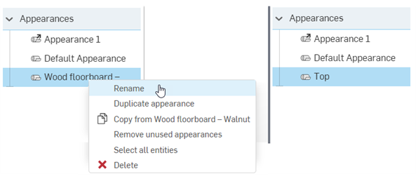
在「Scene list」中的「Appearances」下,於「Wood floorboard」外觀上按右鍵,然後從環境選單中選擇 Rename。將外觀重新命名為 "Top"。 這樣同時也會重新命名右側「Appearances」面板中的外觀。
-
在「Scene list」中取消選取 table top,然後多重選取 (Ctrl/Cmd+選擇) 桌腳。在 Floorboards - Walnut 上按右鍵然後從環境選單中選擇 Assign。系統隨即將這個外觀套用至四個桌腳上。
-
在「Scene list」中的「Appearances」下,於「Wood floorboard」外觀上按右鍵,然後從環境選單中選擇 Rename。接著將外觀重新命名為 "Legs"。
-
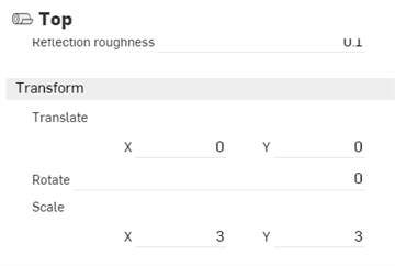
點按 Top 外觀縮圖來選取該外觀。在右側「外觀」面板的「Transform」子功能表中,輸入 3 x 3 的比例。這樣會將外觀圖案轉換大於桌面而移除樓板溝槽:
-
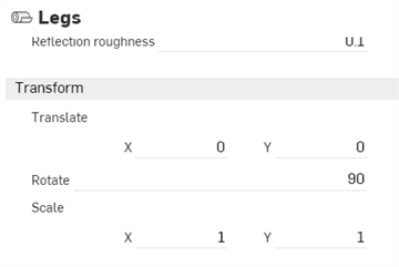
在「Appearance」資源庫中按一下 Legs 外觀的縮圖。在「Appearance」面板的「Transform」子功能表中輸入 90 度的「Rotation」值。這樣會建立沿著桌腳外觀的垂直木板。由於在場景「Appearance」資料夾中「Legs」外觀是與四個桌腳相關聯的,因此會以群組的方式同時轉換:
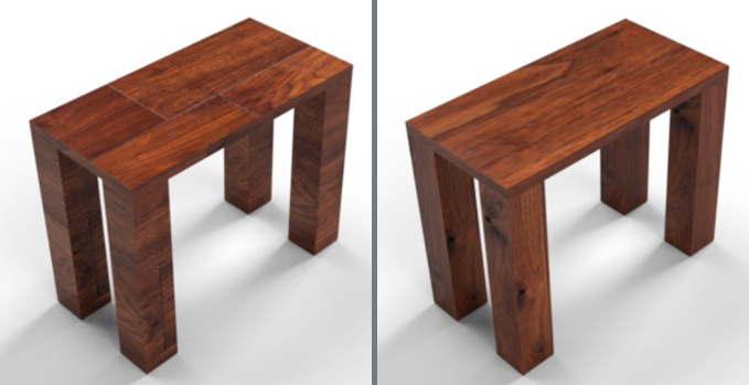
使用預設 Walnut - Floorboards 外觀的桌子模型 (左圖),與變換外觀之後的模型 (右圖)。
所做的調整可能不會產生與此處範例圖片中所示相同的結果。特別是在使用「Transform」選項時,模型的大小會有很大的影響。可能需要將外觀放大或縮小於 X: 3、Y: 3。
選擇性使用,若要更細微地控制外觀的轉換,請將相同或不同的外觀套用到每個零件面上,然後個別轉換每個面的外觀。操作方式是按一下「Scene list」中零件名稱左側的箭號來展開零件所有的面。
在將外觀套用至場景中的零件或面上時,系統會將外觀放置在「Scene list」底部「Appearances」的部分。這樣可幫助追蹤用於場景中的外觀。將同樣的外觀套用至多個零件中。當選取使用外觀的零件或面,且在「Appearances」面板中編輯該外觀時,使用外觀的其他零件與面也會同時更新。這樣即無需個別更新每個零件或面的外觀。
-
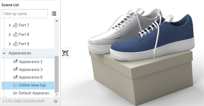
將外觀加入至零件或面中。在下方的圖片中是將藍色的布料套用到其中一隻鞋子上。
-
重新命名外觀。這樣可幫助在之後找出「Scene list」中的外觀,特別是在有許多外觀的複雜場景中。
-
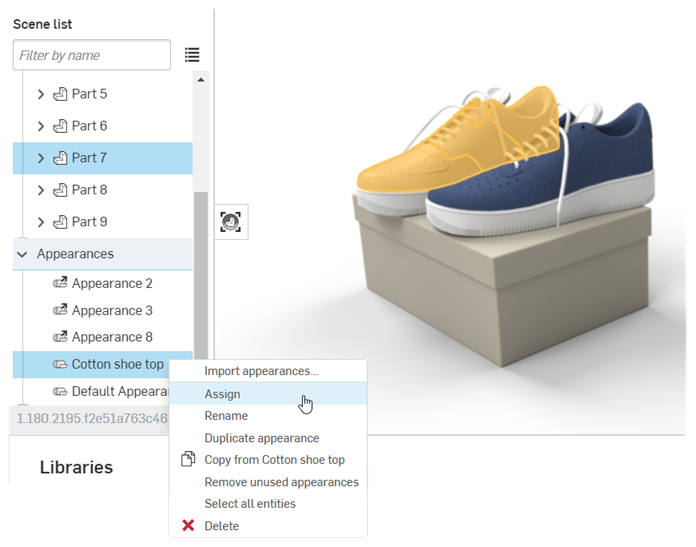
在「Appearances」資源庫的「Scene appearances」資料夾中找出外觀,然後將外觀指定給場景中任意數量的其他零件或面:
-
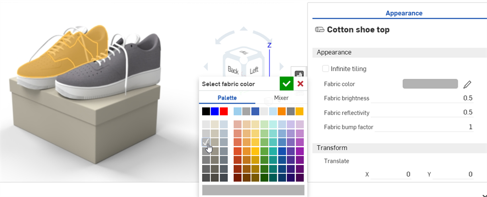
使用「Appearance」面板來編輯外觀。例如,在下方的圖片中已將鞋子的織料改為灰色。注意到兩隻鞋子都更新為改用新的色彩屬性,即使只單選了一隻鞋子:
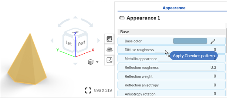
將紋理套用至零件的一個外觀參數中。這個程序說明如何將紋理套用至零件的「Diffuse roughness」參數中。
-
在「Scene list」或圖形區域中選擇零件。
-
展開「Appearance」面板中的「Base」子功能表 (如果尚未展開的話)。
-
在「Appearances」資源庫中選擇「Appearance functions」資料夾。
-
找出 Checker pattern 函式,在「Appearances」資源庫中按一下並拖曳函式,然後將其放置在右側「Appearance」面板中「Base」子功能表的「Diffuse roughness 」參數上。
-
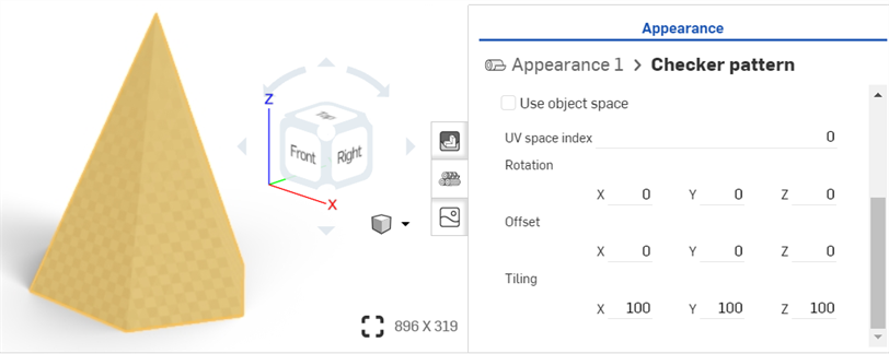
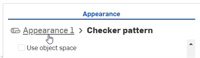
系統隨即套用紋理並自動在「Appearances」面板中開啟紋理。可以從「Appearances」面板最上方的階層式導覽路徑來確認。使用「Appearances」面板中的子功能表來將 Checker pattern 的參數調整為不同的規格:
-
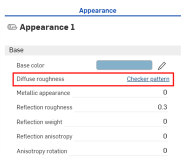
按一下「Appearances」面板最上方的 Appearance 1 導覽路徑連結 (下方中第一個圖片所示) 來回到零件的外觀面板中。若要再次編輯紋理,按一下「Diffuse roughness」參數旁的紋理連結 (下方中第二個圖片所示):
在放下紋理之前,注意到系統以藍色強調顯示許多外觀參數。這表示可以將紋理套用到任何的這些參數上。請將縮圖放置在所選的參數上。詳細資訊請參考使用外觀函式。
這個過程說明如何將自訂影像 (例如 PNG 或 JPG) 做為紋理套用到面或零件外觀的 Base color 參數上。不過,如果需要,您可以修改這個步驟來將紋理套用到數個其他外觀參數上。
另一種方式將自訂影像套用為紋理的方式是使用「Appearance」面板中外觀參數的環境選單。請參考套用紋理至參數上。
-
如果您的紋理影像尚未匯入至您的文件中,按一下插入新分頁圖示 (
 ),然後選擇匯入:
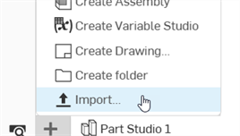
-
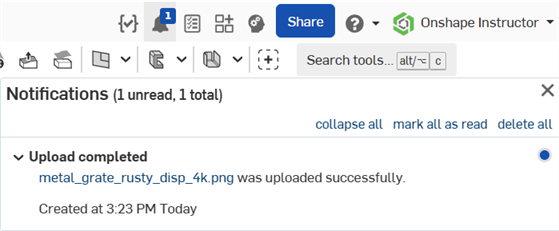
在匯入檔案之後您後看到一個通知:
-
在「Scene list」或圖形區域中選擇面和/或零件。
-
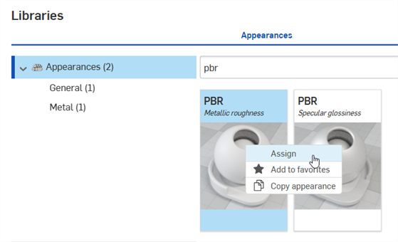
在資源庫中找出「PBR - Metallic roughness」外觀。於其上按右鍵,然後從環境選單中選擇指派:
-
在「Appearance」面板中設定外觀的一些基本參數,像是 Metallic、Brightness、Opacity 等項目以達到您的要求。
-
找出,然後將 Import bitmap file - Bitmap texture 函式拖放到「 Appearance」面板中 PBR - Metallic roughness 外觀的 Base color 參數上:
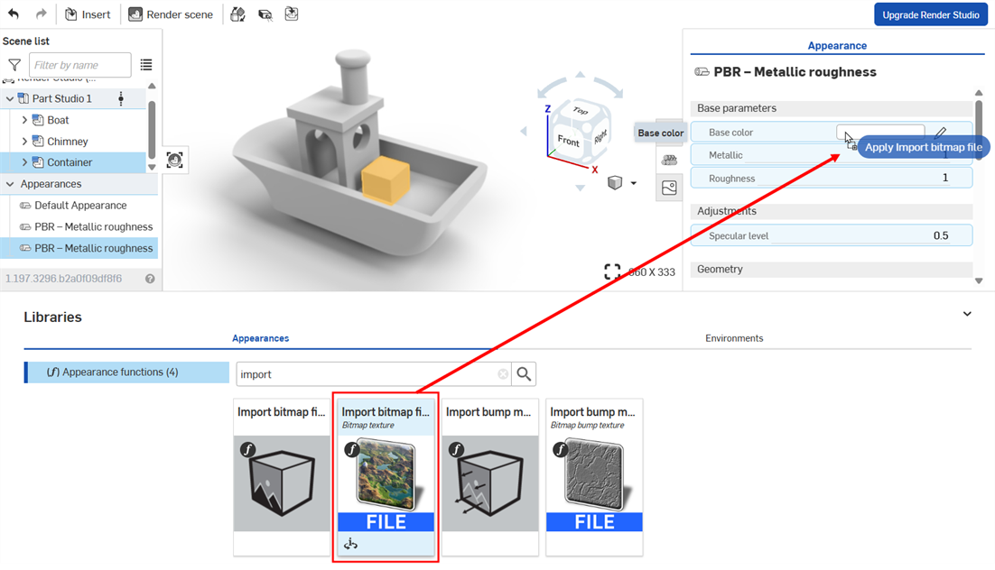
在放下紋理之前,注意到系統以藍色強調顯示許多外觀參數。這表示可以將紋理套用到任何的這些參數上。請將縮圖放置在所選的參數上。詳細資訊請參考使用外觀函式。
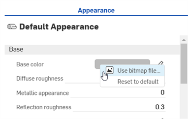
或者是,在參數上按右鍵,然後選擇 [Use bitmap file],接著選擇您匯入的檔案來將其套用到參數上:
-
按一下預設的 black.png Bitmap 檔案,然後選擇您稍早匯入至文件中的紋理影像 (下方中第一個圖片所示)。紋理會套用至所選的面和/或零件上 (下方中第二個圖片所示):
如果您在已建立 Render Studio 分頁後匯入紋理,您會需要建立文件的一個版本,才能夠從「選擇影像」對話方塊中存取紋理。
-
修改影像上紋理的 Rotation、Offset 與 Tiling 以達到您的要求。
設定 Tiling 為 x: 20; Y: 20
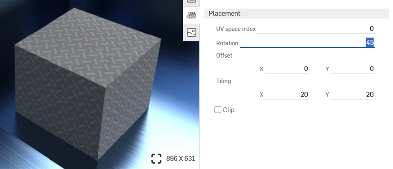
設定 Rotation 為 45 度
-
按一下工具列上的 Projector 圖示 (
 ) 來開啟「Projector」對話方塊。
 -
在「Entities to add projector to」欄位中選擇您要套用紋理的面和/或零件。
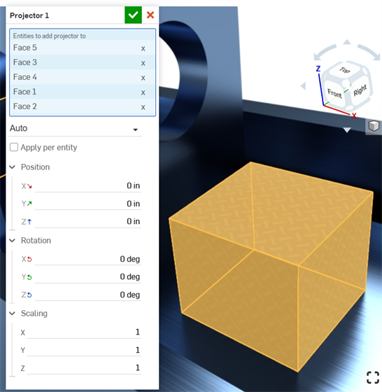
-
選擇 Position、Rotation、與 Scaling 選項來達成您指定的需求。
凹凸紋理 (或凹凸貼圖) 模擬零件的表面紋理。法線貼圖是一個特定類型的紋理,可將凹凸的細節 (皺褶、溝槽、草皮圖案等等) 加入至模型中,當光線在表面上反射時,即會模擬產生真實的幾何。
凹凸紋理不是直接套用到零件上的,而是套用到零件外觀的「Bumps」參數上。
-
在「Scene list」或圖形區域中選擇零件。
-
展開「外觀」面板中的「Global」子功能表 (如果尚未展開的話)。
-
在「Appearances」資源庫中選擇「Appearance functions」資料夾。
-
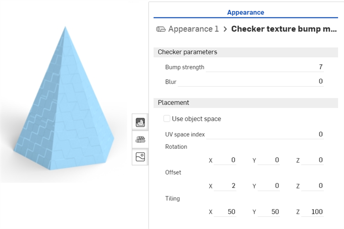
找出 Checker texture bump map 函式,在「外觀」資源庫中按一下並拖曳函式,然後將其放置在右側「外觀」面板中的「Bumps」參數上。
-
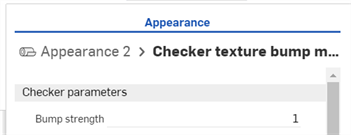
在套用之後,使用 Appearance 1 > Checker texture bump map 面板子功能表來調整凹凸紋理參數:
-
按一下「外觀」面板最上方的外觀導覽路徑連結 (下方中第一個圖片所示) 來回到零件的「外觀」面板中。若要再次編輯凹凸紋理,請在「Global」子功能表中找出紋理,然後點按紋理的連結 (下方中第二個圖片所示):
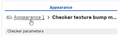
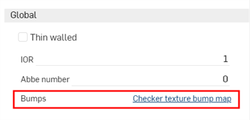
在放下凹凸紋理之前,注意到系統僅以藍色強調顯示「Bumps」參數。這表示僅能將凹凸紋理套用到這個參數上。詳細資訊請參考使用外觀函式。
凹凸紋理 (或凹凸貼圖) 模擬零件的表面紋理。法線貼圖是一個特定類型的紋理,可將凹凸的細節 (皺褶、溝槽、草皮圖案等等) 加入至模型中,當光線在表面上反射時,即會模擬產生真實的幾何。
凹凸紋理不是直接套用到零件上的,而是套用到零件外觀的「Bumps」參數上。
-
在「Scene list」或圖形區域中選擇零件。
-
展開「外觀」面板中的「Global」子功能表 (如果尚未展開的話)。
-
在「Appearances」資源庫中選擇「Appearance functions」資料夾。
-
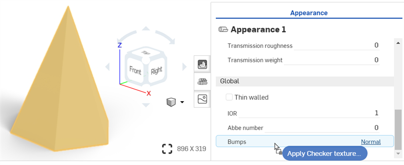
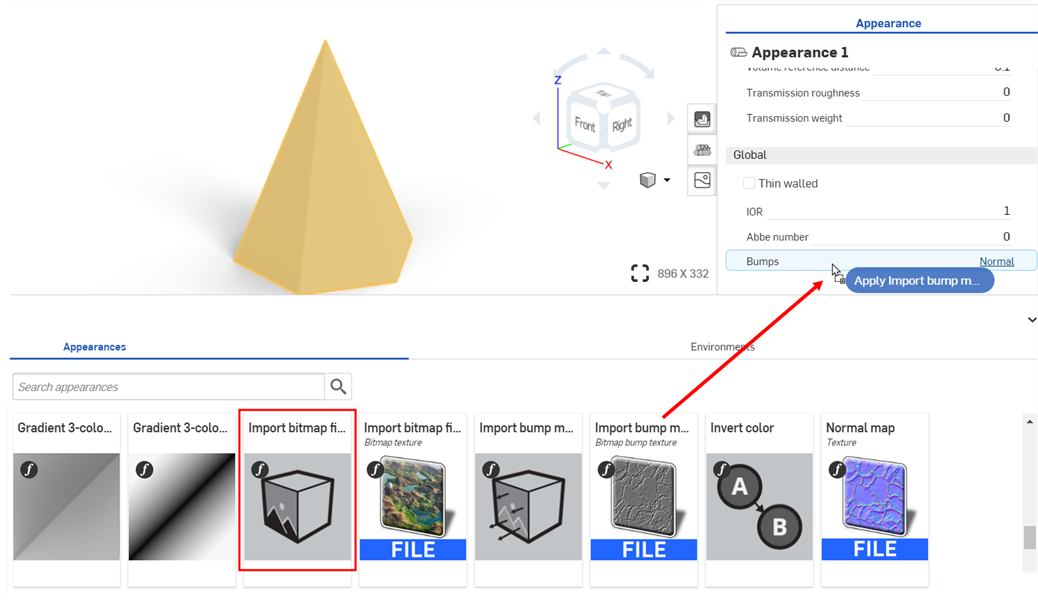
找出 Import bump map file 函式,然後將其拖放到「Global」子功能表的「Bumps」屬性上。
-
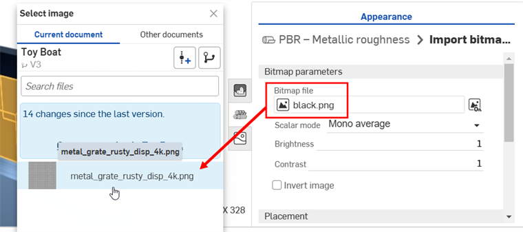
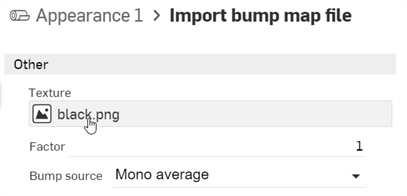
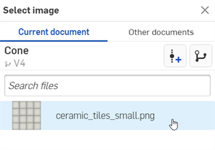
在「外觀」面板中,按一下 Bitmap file (black.png)。這樣會開啟「選擇影像」對話方塊:
-
執行下列操作之一:
-
從「目前文件」中選擇一個檔案凹凸貼圖檔案
-
按一下其他文件來找出在另一個 Onshape 文件中的檔案
-
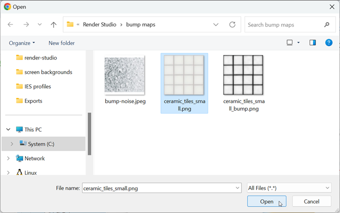
按一下對話方塊底部的匯入連結來從您電腦中找出一個凹凸貼圖檔案 (.jpg 或 .png)。選擇之後按一下開啟按鈕:
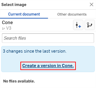
當通知顯示上傳完成時,您還不會在「選擇影像」對話方塊中看到影像。這是因為 Render Studio 場景是匯入時零件、Part Studio 或組合件的快照,而這個影像是匯入之後才帶入至 Onshape 文件中的,因此現在需要一個新的版本才能更新場景。在「選擇影像」對話方塊中按一下在 [Document name] 中建立一個版本的連結:
建立版本對話方塊開啟。輸入版本資訊然後按一下 建立 按鈕。
-
-
在建立新版本之後,.ies 檔案會位在「Select light profile」之中。點按以選擇它:
-
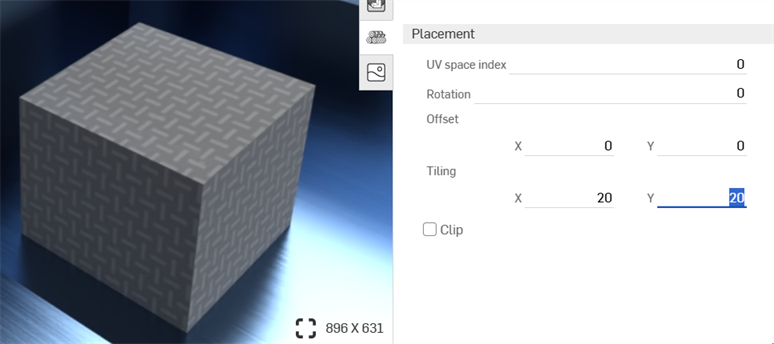
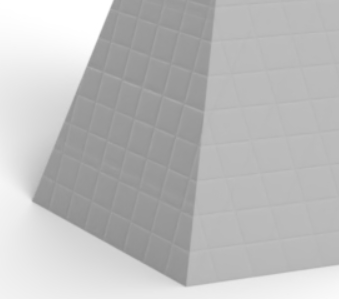
在選擇之後,檔案會被載入至「Bitmap file」欄位中。使用「Bitmap」和「Placement」子功能表來編輯凸紋理的參數:
-
Tiling - 控制零件上紋理的縮放。較大的數字會降低紋理的數量 (更多拼貼),較小的數字則會增加紋理的數量 (較少拼貼)。
-
Clip - 如果啟用,不會重複紋理,且在紋理之外的都會顯示為平坦。
-
Offset - 控制零件上紋理的位置
-
Rotation - 控制零件上紋理的旋轉,單位是度。
-
Bump mode - 定義如何求值紋理來建立凹凸。
-
Bump strength - 控制凹凸貼圖拼排的強度。
或者,使用「Import bitmap file」函式 (如下方紅色方框中所示) 來執行更複雜的紋理編輯功能。複雜圖形的紋理放置功能是與 file_texture maps 相連結的。
在放下凹凸紋理之前,注意到系統僅以藍色強調顯示「Bumps」參數。這表示僅能將凹凸紋理套用到這個參數上。詳細資訊請參考使用外觀函式。
如果您在「選擇影像」對話方塊中沒有看到建立版本的連結,請按一下文件面板中的「建立版本」按鈕 (![]() ) 來開啟建立版本對話方塊。請建立新版本,然後關閉並重新開啟「選擇影像」對話方塊。現在即可使用匯入的影像。
) 來開啟建立版本對話方塊。請建立新版本,然後關閉並重新開啟「選擇影像」對話方塊。現在即可使用匯入的影像。
關於上傳檔案的詳細資訊,請參考匯入檔案。
有好幾個外觀是專用在場景中以於零件、表面或面上加入與發散光源的。取決於光的來源與應如何照亮要處理的場景,會決定要使用的光源外觀。光發射的外觀略述如下:
| 光源外觀名稱 | 說明 |
| Add emission | 將發射加入至材料中。詳細資訊請參考使用「Add emission」外觀來加入光源。 |
|
Add thermal emission |
將發射加入至材料中,色彩是基於「色溫」的。詳細資訊請參考加入熱發射外觀。 |
| Light source emitter — 1900k candle | AEC - 光 - 燭光 1900k 發射體。詳細資訊請參考其他的光源範例。 |
| Light source emitter — 7000k cool white emitter | AEC - 光 - 冷白 7000k 發射體。詳細資訊請參考其他的光源範例。 |
| Diffuse area light | 漫射散發至各處的區域光源材料。詳細資訊請參考其他的光源範例。 |
| Display screen | 設計 - 光 - 顯示螢幕 (照亮螢幕來顯示)。詳細資訊請參考顯示螢幕。 |
| Light source emitter — 5000k fluorescent | AEC - 光 - 螢光 5000k 發射體。詳細資訊請參考其他的光源範例。 |
| Light source emitter — 3000k halogen | AEC - 光 - 鹵素 3000k 發射體。詳細資訊請參考其他的光源範例。 |
| IES light | 2 個外觀:(1) 具有 Ies 定義的分布特性的光源材料。(2) IES 設定檔驅動的光源材料,縮放原始的資料以產生特定的通量。詳細資訊請參考加入自訂的 IES 光源設定檔。 |
| Light source emitter — 4000k natural white | AEC - 光 - 自然白 4000k 發射體。詳細資訊請參考其他的光源範例。 |
| 光度光源 | 由 IES 光度設定檔驅動的光源材料。請注意,對於使用絕對測量的設定檔 (例如對 LED) ,乘數引數應設定為 1.0。詳細資訊請參考其他的光源範例。 |
| Spot light | 3 個外觀:(1) 具有造型發射特性的光源材料。(2) 具有全域 (對齊物件方向) 分布的聚光燈材料。(3) glTF 2.0 聚光燈源。關於聚光燈的兩個範例,請參考加入聚光燈與反射性的表面以及加入體積與體積係數。 |
| Light source emitter — 2700k warm white | AEC - 光 - 暖白 2700k 發射體。詳細資訊請參考其他的光源範例。 |
將光發射加入到場景中任何零件上的簡單方法:
-
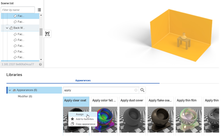
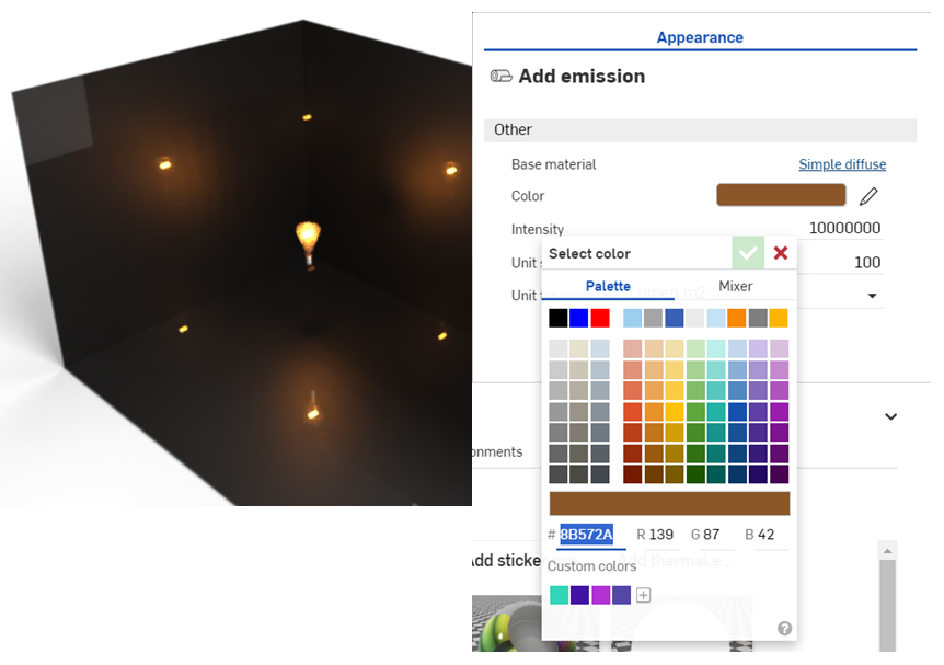
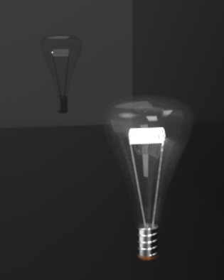
在 Part Studio 或組合件中,建立一個用做為光源的零件,然後在零件周圍加入牆壁。在這個範例中已建構一個燈泡,並有側邊牆壁與一個地板:
-
在「Scene list」中選擇 walls (牆)。
-
在「外觀」資源庫中,搜尋 apply。在「Apply clear coat」外觀上按右鍵,然後在環境選單中按一下指派。這樣會加入反射性的表面可反射光源散發的光線:
-
在「Scene list」或圖形區域中,選擇 bulb glass cover (燈泡的玻璃蓋)。
-
.在「外觀」資源庫中,找出 Thin glass 外觀。在其縮圖上按右鍵,然後在環境選單中按一下指派。
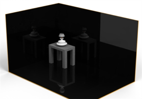
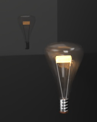
在下方的範例中,已將金屬套用至螺旋底座,銅材套用至燈泡底部的接頭。最後移除了燈座、燈罩與桌子來更好地展現燈泡光線的散發。
-
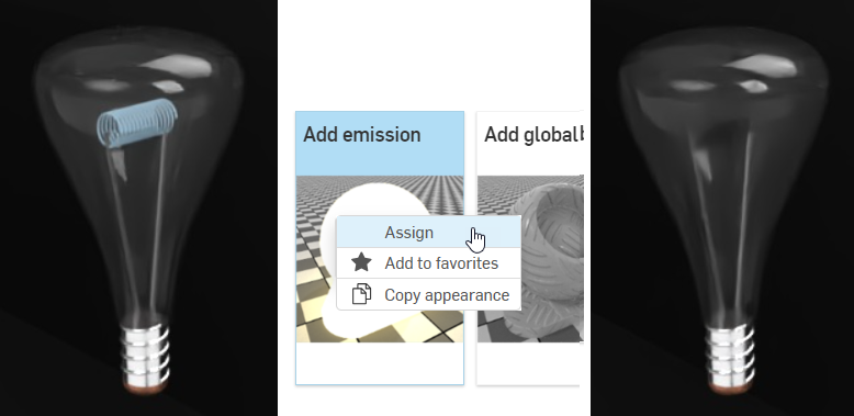
在「Scene list」中,選擇用做為燈泡內燈絲的零件 (下方中左側圖片所示)。
-
在「外觀」資源庫中,找出 Add emission 外觀。在其縮圖上按右鍵,然後在環境選單中按一下指派 (下方的中間圖片所示)。燈絲一開始是深色的 (下方中右側圖片所示):
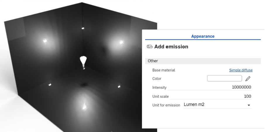
外觀的選項有:
-
Base material - 將發射加入至其上的材料。預設是漫射的。
-
Intensity - 光源的亮度。預設值是 1000。
-
Color - 光發射的顏色。預設是白色 (R: 255; G: 255; B: 255)。
-
Unit for emission - 「Intensity」的物理單位。預設是 Lumen m2。其他的選項有 Lumen、Candela 與 Nit。
-
Unit scale - 建構單位與米的轉換係數。預設值是 100。
-
-
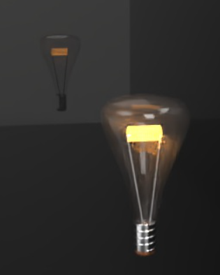
在「外觀」面板中上調發射「Intensity」。請注意,這個值主要是取決於場景的大小。供您參考,下方所建立房間的尺寸是長 2.43 米、寬 .97 米與高 .84 米。「Intensity」值是設定為 10000000。這樣會產生放射性的白光:
-
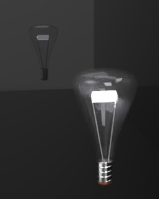
調整色彩來控制光源發射的冷暖色調。下方的範例顯示選擇一個新顏色時,光源散發的變化:
-
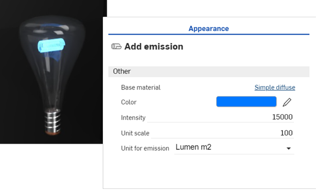
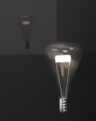
放大燈泡,減少強度然後將顏色改為藍色,以建立一個如下所示的散發:
-
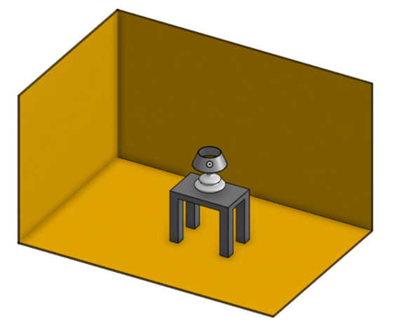
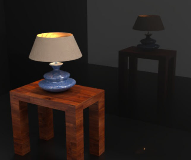
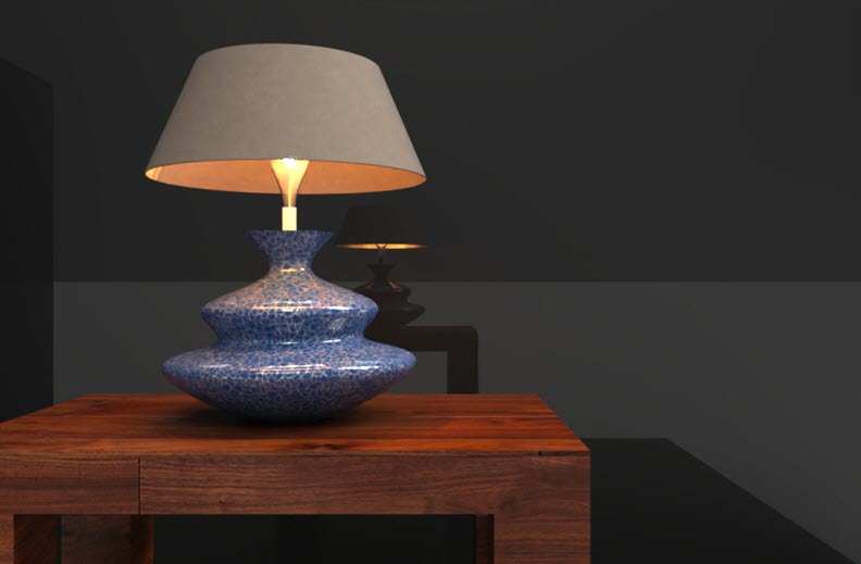
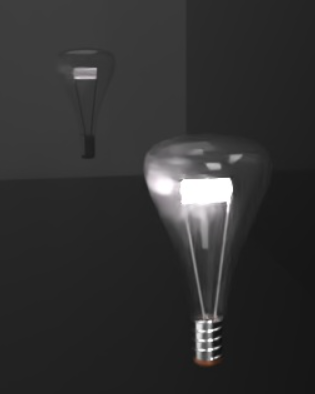
最終的範例顯示如何在加入檯燈和桌子的完成場景中使用光源燈泡。注意到燈泡上的燈罩會如何將光的發射重新導向上下兩個方向,以及在光源與牆壁間放置燈罩後光發射變暗:
與「Add emission」外觀類似,「Add thermal emission」 外觀會將光源加入至建構的零件、表面或面上。不過在這個外觀中是將光源視為熱源。「Color」參數會由「Temperature」參數所取代,會調整這個參數來定義熱源的類型。
-
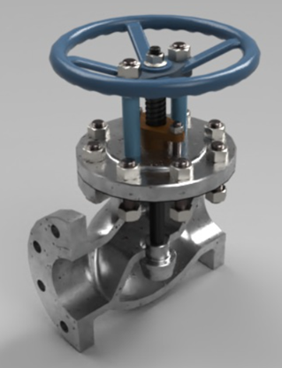
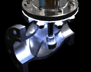
在建構模型之後,從 Part Studio 或組合件中建立一個場景。此處使用的範例是一個閥門組合件:
-
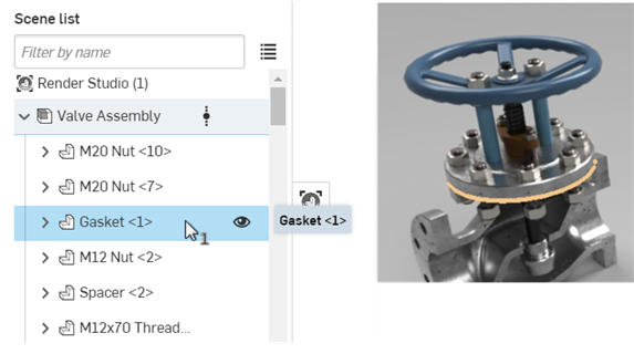
在「Scene list」或圖形區域中選擇零件。這是用做為熱發射起源的零件。在下方的範例中,墊片 (gasket) 是發射的來源:
-
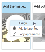
在「外觀」資源庫中,找出 Add thermal emission 外觀。在其縮圖上按右鍵,然後在環境選單中按一下指派:
-
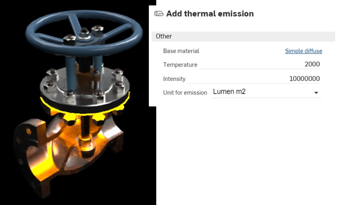
在「外觀」面板中上調「Intensity」。在這個場景中,「Intensity」是設定為 10000000。接著再將「Temperature」設定為 2000。這樣會產生橘色的熱發散:
-
將「Temperature」值設定為 65000 會將發射色彩變更為藍色。例如,表示來自碳氫化合物來源的熱,像是丁烷或丙烷瓦斯:
就一般的規則而言,從 0 到 3500 的值是在紅-橘-黃的範圍,而從 10000 往上的數字是在藍色範圍。預設 6500 的值會發射白色光。
IES light profiles 會描述來自燈具光線的分布。這個資料是由許多製造商所提供,這樣設計人員可以逼真地渲染呈現房間內的光源。
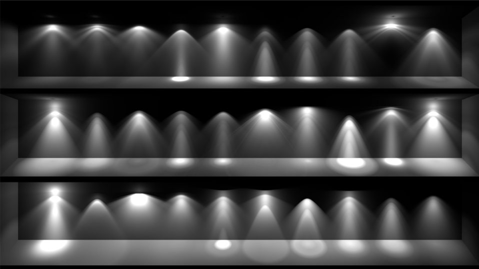
數個 IES profiles 的範例
Render Studio 可以將 IES light profile 加入至光源中。
-
在「Scene list」或圖形區域中選擇零件或面。
-
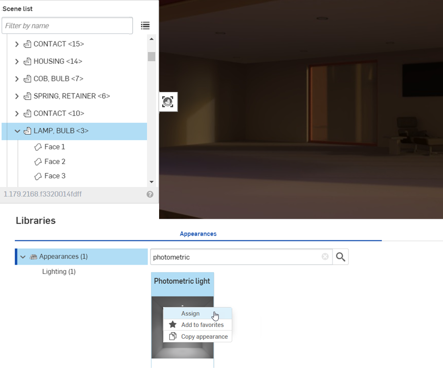
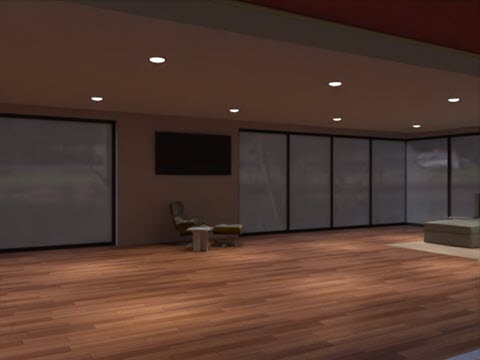
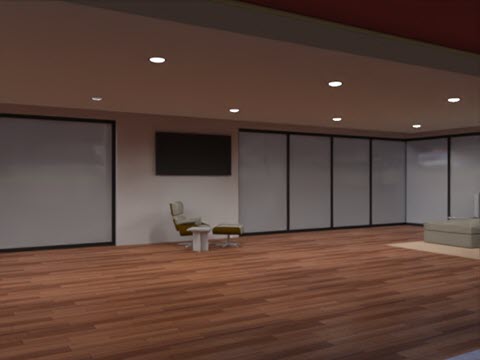
搜尋「外觀」資源庫找出 Photometric。在「Photometric light」縮圖上按右鍵,然後在環境選單中按一下指派。下方的範例是一個有非常暗環境的客廳:
-
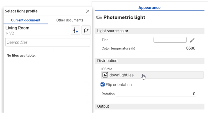
在「外觀」面板 >「Distribution」子功能表中,按一下 IES file (downlight.ies)。這樣會開啟「Select light profile」對話方塊。
-
執行下列操作之一:
-
從「目前文件」中選擇一個 IES 檔案
-
按一下其他文件來找出在另一個 Onshape 文件中的 IES 檔案
-
按一下對話方塊底部的匯入連結來從您電腦中找出一個 IES 檔案。選擇之後按一下開啟按鈕:
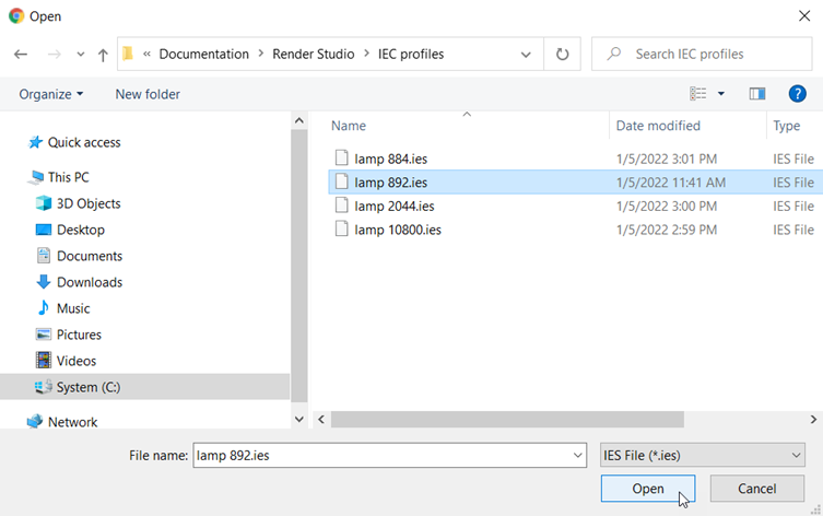
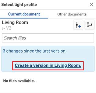
當通知顯示上傳完成時,您還不會在「選擇影像」對話方塊中看到影像。這是因為 Render Studio 場景是匯入時零件、Part Studio 或組合件的快照,而這個影像是匯入之後才帶入至 Onshape 文件中的,因此現在需要一個新的版本才能更新場景。在「選擇影像」對話方塊中按一下在 [Document name] 中建立一個版本的連結:
建立版本對話方塊開啟。輸入版本資訊然後按一下 建立 按鈕。
-
-
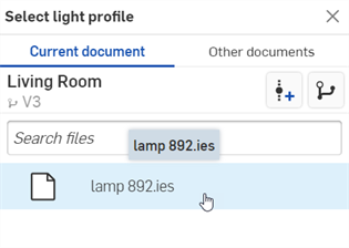
在建立新版本之後,IES 檔案會位在「Select light profile」之中。點按以選擇它:
-
選擇之後,系統會將檔案載入至「IES file」欄位中:
-
在「Appearance」面板子功能表中編輯參數。例如,修改「 Tint」來改變光的顏色,調整「Lumens or multiplier」來增加光源的強度。在下方的範例中,將 IES profiles 套用至客廳天花板的崁燈中:
如果您在「Select light profile」對話方塊中沒有看到建立版本的連結,請按一下文件面板中的「建立版本」按鈕 (![]() ) 開啟建立版本對話方塊。請建立新版本,然後關閉並重新開啟「Select light profile」對話方塊。現在即可使用匯入的影像。
) 開啟建立版本對話方塊。請建立新版本,然後關閉並重新開啟「Select light profile」對話方塊。現在即可使用匯入的影像。
關於上傳檔案的詳細資訊,請參考匯入檔案。
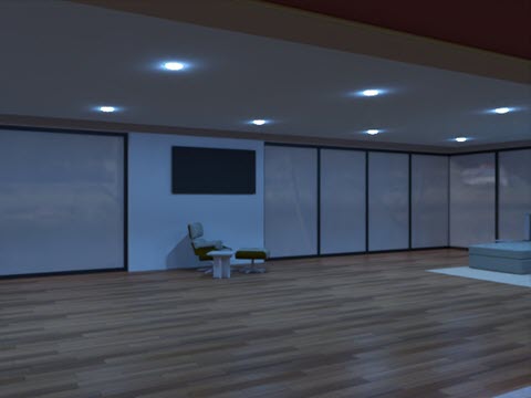
下方是光源的兩種變化。第一個圖片使用的 IES profile 有比上方範例所用更寬的發射擴散,而第二個圖片使用的 IES profile 會在燈泡周圍散發出月暈的效果。「Emission color」是設定為藍色:
關於免費 IES profiles 的集錦,請造訪 https://ieslibrary.com/en/home
「Display screen」是一種非常特定類型的外觀,可用來仿製在電視、電腦或其他數位螢幕上的圖片。選項有:
-
Image - 開啟「選擇影像」對話方塊,您可以在其中找出要映射到顯示上的影像。
-
Repeat image - 如果啟用,圖片會橫跨 UV 座標重複。如果停用,則會橫跨 UV 座標顯示圖片的單一實例。預設是啟用的。
-
Intensity - 顯示發射的強度。預設值是 40。注意到當套用這個外觀時,光源最有可能是黑色的,將強度增加為較高的值應會產生足夠的強度可查看發射。這會取決於您場景的大小。
-
Screen roughness - 較高的粗糙度值會導致較大的強光亮點與較模糊的反射。預設值是 0.2。
-
Translate - 沿 x 與 y 軸控制影像的位置。
-
Rotate - 以度為單位旋轉影像的角度。
-
Scale - 沿 x 與 y 軸縮放影像大小。較大的數字會增加大小。較小的數字會減少大小。
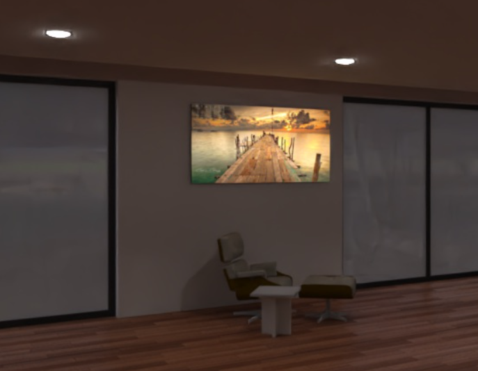
顯示螢幕光源的範例 (套用至牆上螢幕的正面)
Intensity: 200000
下列的光源都使用相同的基本發射體參數,只有「Color temperature」值有所不同:
-
Color temperature - 以克耳文為單位的色彩溫度。
-
Lumens (flux) - 光源發射出的發光通量,以流明為單位。預設值是 1000。
-
Two-sided emission - 如果為真,會在幾何的正面與背面發射。預設是停用的。
|
1900k candle |
7000k cool white |
5000k fluorescent |
3000k halogen |

4000k natural white |
2700k warm white |

「Diffuse area light」的選項如下:
Diffuse area light:
-
Flux - 光源發射出的總發光通量 (以流明為單位)。預設值是 500。
-
Scene unit size - 將米轉換為場景單位。範例:在場景中 1.0 是一英呎的狀況下,場景單位大小 = 0.30481.0;場景是以釐米為單位的狀況下,場景單位大小 = 0.01。
-
Emission color - 光源的顏色。將會以不影響光通量的方式調整。預設值是白色 (R: 255; G: 255; B: 255)。
-
Two-sided emission - 如果為真,會在幾何的正面與背面發射。預設是停用的。
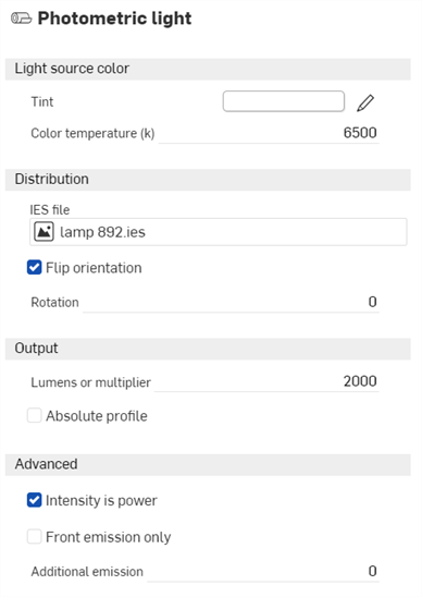
「Photometric light」的選項如下:
Photometric light:
-
Tint - 發射光的其他濃淡色彩 (例如,模擬凝膠)。預設值是白色 (R: 255; G: 255; B: 255)。
-
Color temperature - 以克耳文為單位的色彩溫度。預設值是 6500。
-
IES file - 用來指定光線分布的 IES light profile。詳細資訊請參考加入自訂的 IES light profile。
-
Flip orientation - 重新調整光源設定檔的上向量,根據預設這是朝向 y 方向的,調整將其朝向 z 方向。預設是啟用的。
-
Rotation - 繞光源設定檔的上向量旋轉分配。預設是停用的。
-
Lumens or multiplier - 光的強度。如果停用了「Absolute Profile」,則這就是光源的流明輸出。如果是啟用的,則這是套用至原始光源設定檔強度的乘數。預設值是 2000。
-
Absolute profile - 控制強度是光的流明輸出 (停用) 或是乘以原始的光輸出 (啟用)。預設是停用的。
-
Intensity is power - 如果啟用的話,強度將會被解讀為功率。因此,會用光源面積除以輸出量來產生輻射。意即如果放大光源表面積,場景的亮度仍會維持為相同的。預設是啟用的。
-
Front emission only - 停用區域光源背面的發射。這對圓柱狀的光源是必須的,可避免光線從開放的圓柱端蓋露出。技術上而言也應該為球形光源設定,即使光線並不會露出。預設是停用的。
-
Additional emission - 用來將基本的朗伯 (Lambertian) 發射加入至光源中。當直接檢視時,對避免暗的光源相當有用。預設值是 0。
Photometric light 的範例
Lumens or multiplier: 20000; Flip orientation: 停用
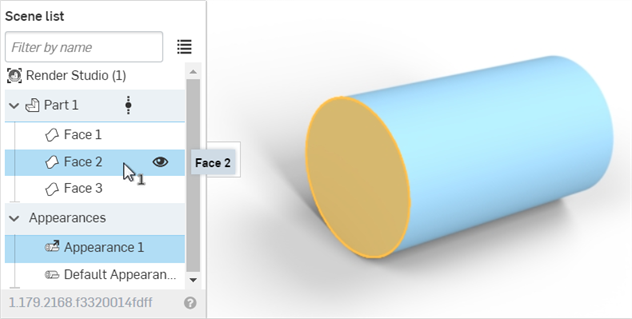
建立透明的零件面:
-
在「Scene list」或圖形區域中選擇零件或面。
-
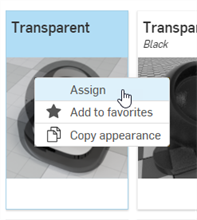
搜尋「Appearance」資源庫中的 Transparent。在透明縮圖上按右鍵,然後按一下指派:
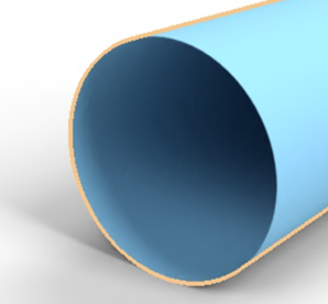
在下方範例中,透明度會套用到圓柱的前端面。該面依然存在,只是透明穿透其他面:
常見的操作是將一個標誌或文字放置在表面或零件上。
雖然在此處說明的方法是將貼圖加到表面或零件上的有效方式,現在當插入使用「印花」特徵的 Part Studio 時,Render Studio 會自動匯入印花。這個是建議使用的方式。詳細資訊請參考操作印花。
-
建立一個模型並將其帶入至 Render Studio 場景中。
-
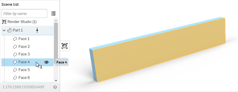
在「Scene list」或圖形區域中選擇零件或面:
-
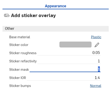
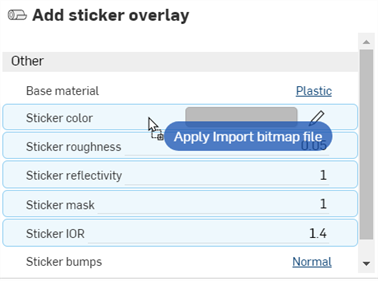
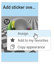
在「Appearances 」資源庫中,搜尋 sticker,然後在「Add sticker overlay」縮圖上按右鍵,接著從環境選單中選擇指派:
-
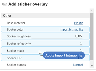
在「Appearance」面板中,將「Sticker mask」設定為 1:
-
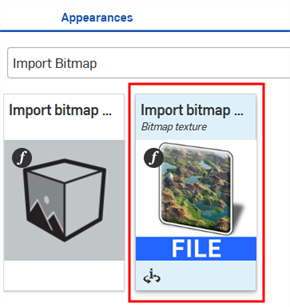
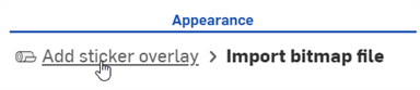
在「Appearances 」資源庫 >「Appearance functions 」資料夾中找出 Import bitmap file — Bitmap texture 函式 (下方第一個圖片),然後將其拖放到「外觀」面板中的「Sticker color」參數上 (下方第二個圖片)。這樣可以選擇用做為貼圖的檔案。
-
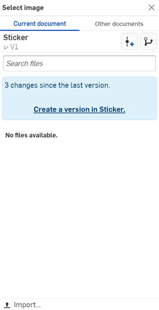
按一下 Bitmap file (black.png) 來開啟「選擇影像」對話方塊。
-
執行下列操作之一:
-
從「目前文件」中選擇一個檔案凹凸貼圖檔案
-
按一下其他文件來找出在另一個 Onshape 文件中的檔案
-
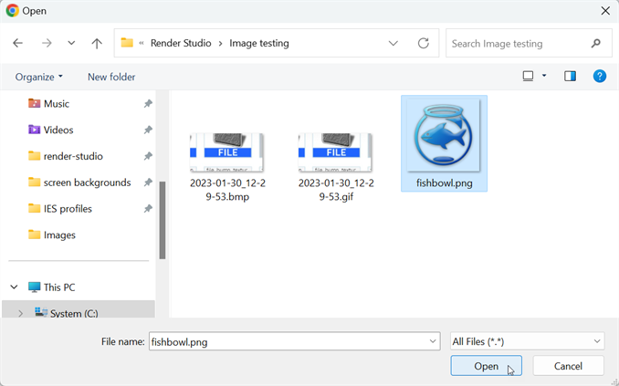
按一下對話方塊底部的匯入連結來從您電腦中找出一個凹凸貼圖檔案 (.jpg 或 .png)。選擇之後按一下開啟按鈕:
當通知顯示上傳完成時,您還不會在「選擇影像」對話方塊中看到影像。這是因為 Render Studio 場景是匯入時零件、Part Studio 或組合件的快照,而這個影像是匯入之後才帶入至 Onshape 文件中的,因此現在需要一個新的版本才能更新場景。在「選擇影像」對話方塊中按一下在 [Document name] 中建立一個版本的連結:
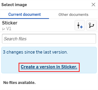
建立版本對話方塊開啟。輸入版本資訊然後按一下 建立 按鈕。
-
-
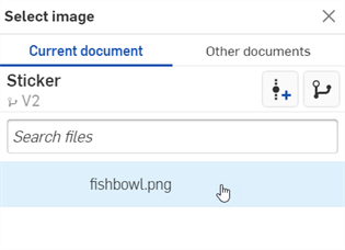
在建立新版本之後,貼圖檔案會位在「選擇影像」對話方塊中。點按以選擇它:
-
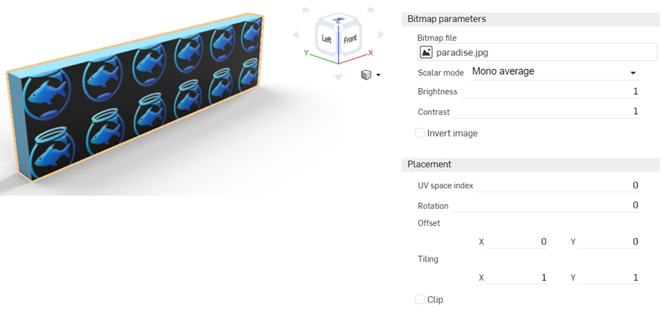
選擇之後,系統會將檔案載入至「Bitmap file」參數中。使用「Placement」選項來設定貼圖的適當位置。根據預設會將「Tiling」設定為重複的 X: 1、Y: 1,且不會是偏移跟旋轉的:
-
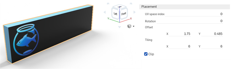
將「Tiling」設定為 6 x 6 來增加圖片的大小,然後核取會迫使貼圖不重複的「Clip」選項。在這裡同時偏移貼圖來顯示面的最左側。請記下這些設定,因為稍後套用遮罩時會需要這些設定。
-
按一下「Appearance」面板最上方的 Add sticker overlay 連結。這樣會將「Appearance」面板帶回至父貼圖。
-
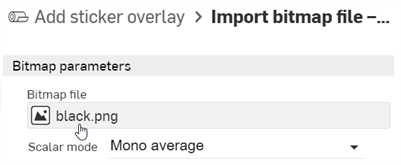
將相同的點陣圖檔案 (與設定) 套用至遮罩中。從「Appearance」資源庫 > Appearance functions 資料夾中拖曳 Import bitmap file — Bitmap texture 函式,然後將其放置在「Appearance」面板中「Add sticker overlay」外觀的「Sticker mask」參數上。在「Placement」子功能表中,輸入之前為貼圖檔案使用的完全相同設定:Tiling、Clip、Offset 與 Rotation。
-
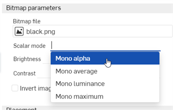
在「Bitmap parameters」子功能表的「Scalar mode」下拉清單中選擇 Mono alpha:
-
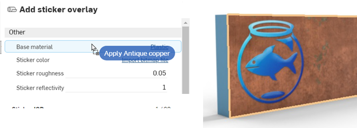
預設的「Base material」參數是 plastic;; 不過,可套用任何外觀到面上而不影響貼圖。從「外觀」資源庫中找出外觀,然後將其拖放到「Base material」參數上以加到面上:
-
如果需要,可將面設定為透明但把貼圖保留在原處,如下所示:
即使貼圖本身有些許的高度,請在建構零件時於您要套用貼圖的主面之上建立一個深度為 .1 mm 的面。然後再如下所述將貼圖套用至這個面上。這樣可產生更逼真的貼圖邊緣。
如果您在「選擇影像」對話方塊中沒有看到建立版本的連結,請按一下文件面板中的「建立版本」按鈕 (![]() ) 來開啟建立版本對話方塊。請建立新版本,然後關閉並重新開啟「選擇影像」對話方塊。現在即可使用匯入的影像。
) 來開啟建立版本對話方塊。請建立新版本,然後關閉並重新開啟「選擇影像」對話方塊。現在即可使用匯入的影像。
關於上傳檔案的詳細資訊,請參考匯入檔案。
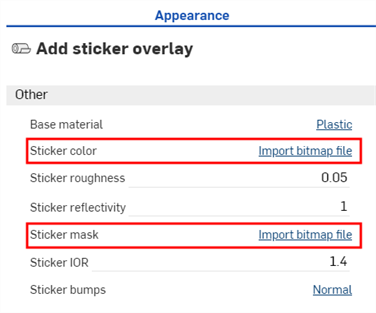
若要修改貼圖和/或遮罩設定,請分別按一下「Sticker color」或「Sticker mask」的 Import bitmap file 連結,然後調整設定。若要讓貼圖與遮罩同步,必須更新兩組設定來使其相符:
詳細資訊請參考 Render Studio 範例與資源。