标记
标记草图轮廓图元以在框架或零件中使用,以从钣金成型中添加或移除。选择几何图元、定义方向并添加特性。


Onshape provides a library of standard structural profiles built directly into the Frame feature. However, there might be times when you need to create a custom library of frame profiles. It is very easy to create and share custom profiles to use with the Frames feature. This video explores how to do this by defining a library of sketches, configuring the profile for different size options, and tagging the profile so that the Cut list table populates with the segments and segment properties.
To create a new profile library, create a new Onshape document. Organize profiles in one or more library documents. Place the library document in a folder at the root of the company or enterprise. This practice makes it easy to share with other users who need to use the profiles.
Create a sketch of the profile in a Part Studio. Create a unique Part Studio for each profile sketch. While sketching, consider how you wish to align the profile. If necessary, add sketch points to serve as additional alignment points. Define the sketch with dimensions and relations. Use variables when defining the sketch dimensions you intend to configure for different profile size options. Variables make it easy to identify the critical values of the profile. Rename the Part Studio and the sketch to describe the profile. The unique name makes it easier for users to understand the intention of your profile. When selecting the profile, the Part Studio name displays at the top level of the dialog, and the sketch name displays below.
If the profile is available in several different sizes with the same shape, configure the sketch dimensions or variable values. Build configuration tables using configuration inputs for each size. Then, configure the dimensions or variables, if used. Edit the sketch, right-click on each dimension to drive the configuration, and select Configure dimension. If you define the sketch with variables, edit the variable, right-click on the value, and select Configure. Edit the values in the configuration table.
Next, start a new Tag feature and select Frame from the dropdown. The Tag feature adds properties to the profile, so when it is used in a Frame feature, the Cut list table displays column headers like Standard and Description, and populates values for those properties.
Select the sketch profile. You can select it from the graphics area or the Features list. If additional alignment points are required, expand the selection field and select points in the sketch to serve as alignment points. Then input numeric or text strings for Standard and Description. If these fields are left blank, that column is not added to the Cut list when the profile is used, or that cell displays “Not set” if other profiles used in the structure have that column header defined. Both Standard and Description inputs can be configured. Right-click on the field in the Tag profile dialog and choose Configure. Then edit the cells in the Configuration table.
To supply more properties for the profile, click Add Column and enter Header and Value information. Repeat as needed to add additional columns to the Cut list table. Click the checkmark when done. These properties cannot be configured. Click the Delete button (X) in the dialog to remove any columns.
Click the checkmark to accept the Tag feature. This profile can now be used with structures contained in this document. Start a new Frame feature in another Part Studio and click the Sketch profile selection in the dialog. In the Current document, select the profile. Adjust the configuration and click Generate to apply the configured values. Then, select the sketch profile.
When building custom profile libraries, keep the profiles in a different document from the designs using them. In this case, version the document that contains the profiles once complete. From then on, the profile can be referenced using linked documents. In this example, a different document contains the custom profiles. Click Other documents, navigate to the document, and select the sketch profile.
To allow other users access to custom profiles, the document or folder containing the profiles must be shared. Users who need to reference the custom profiles in the Frames feature need view and link permissions only. Users who are helping manage the custom profiles need edit and link permissions. Using teams to share is a great way to ensure the right people have access and makes managing access easier. When personnel changes occur in the organization, it is easier to manage adding or removing users on a team than on individual shares.

要标记您创建或修改的轮廓并将切割清单中的信息用作附加列,请执行以下操作:
- Click the Tag icon (
) to open the Tag dialog:
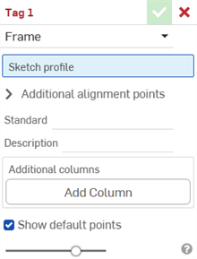
-
为标记目的选择框架
- 在“草图轮廓”输入框中,选择特征列表中充当轮廓草图的草图。
-
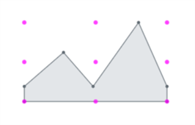
默认情况下,对话框中的“显示默认点”处于启用状态。这将在草图轮廓上叠加一个洋红色的 9 点对齐网格。取消选中此选项可隐藏对齐点。
-
在“其他对齐点”输入框中,在您的草图中选择要用于对齐的任何其他点。
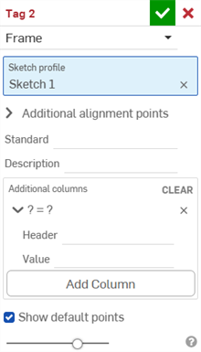
- 在“标准”输入框中,输入要显示在切割清单表格的“标准”列中的值。
- 在“说明”输入框中,输入要显示在切割清单表格的“说明”列中的说明。
- 要为轮廓提供更多信息列,请单击“添加列”:
-
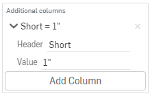
在“标题”输入框中,输入要显示在额外轮廓的切割清单表格中的新列标题的名称,然后输入值:
-
单击“添加列”以再向切割清单表格中添加一个列/值对。
-
单击复选标记 (
)。
最佳实践是标记轮廓、创建一个版本,并在框架中参考该版本的轮廓。
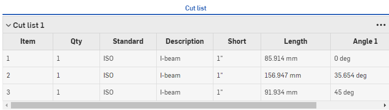
请注意上面“说明”列中的新值,以及额外的列“简短”与相应的值。
轮廓的新信息在框架特征中使用后会出现在切割清单表格中,框架特征后面是用于创建表格的切割清单表格特征。单击窗格右侧的 以打开表格面板。

成型标记指定非钣金零件用作成型特征,用于在钣金模型中添加或移除材料。
要为零件添加标记:
- 单击“标记”图标 (
) 打开“标记”对话框:
-
为标计目的选择成型:
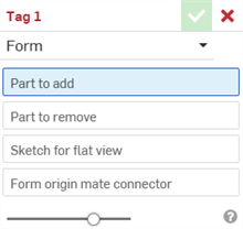
- 在“要添加的零件”输入框中,在零件列表或图形区域中选择要添加到钣金的零件。
- 在“要移除的零件”输入框中,在零件列表或图形区域中选择要减去到钣金的零件。
- 选择“展开视图草图”。这是用于钣金模型展开视图的草图。
- 选择成型原点嵌合连接器。这决定了钣金模型中形状的成型方向。将鼠标悬停在图形区域模型上方可选择隐式或显式嵌合连接器。如果未选择任何选项,则该特征将在 Part Studio 的原点创建一个。
- 单击复选标记 (
)。
请勿选择钣金零件。选择标准几何零件。
请勿选择钣金零件。选择标准几何零件。
每个 Part Studio 只能有 1 个有效成型标记特征。每个 Part Studio 创建 1 个成型。