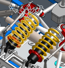
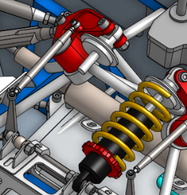
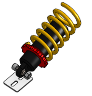
![]()
![]()
![]()
Onshape には、インスタンスの組み立てプロセスを支援するために、コンテキストメニューでいくつかの便利なツールが用意されています。
- 非表示/表示
- 分離
- 透明にする
これらのコマンドを使用すると、関連するエンティティにアクセスするときに、インスタンスやサブアセンブリの検索や移動に手間取ることなく、タスクに必要なインスタンスや合致にアクセスできるようになります。
ショートカット: 非表示 - y / 表示 - Shift+Y
選択した Part Studio エンティティまたはアセンブリエンティティを表示/非表示にします。スケッチ、パーツ/インスタンス、サーフェス、合致、フォルダ、またはグループなどがあります。非表示/表示はトグルコマンドのセットで、Part Studio のパーツリスト、アセンブリのインスタンスリスト、またはグラフィック領域でモデルにカーソルを置いたときのコンテキストメニューで使用できます。
非表示/表示を使用:
-
他のエンティティによって非表示になっている可能性のあるエンティティ (たとえば、他のパーツによって隠されているパーツ) にアクセスしやすくするため
-
指定したタイプのすべてのエンティティを表示するため (たとえば、アセンブリのすべての合致を表示する)
-
相互に幾何学的に依存しているパーツをモデリングする場合
-
インコンテキスト編集をする場合。
使用可能なコマンド:
-
非表示/表示 - グラフィック領域でのモデルエンティティの表示を無効または有効にします。
-
すべてを非表示/表示 - 現在のタブで同じタイプのすべてのエンティティを表示または非表示にします。たとえば、アセンブリのインスタンスリスト内のインスタンスを右クリックして [すべてのインスタンスを非表示にする] を選択すると、アセンブリのすべてのインスタンスが非表示になります。
-
その他を非表示/表示 - 現在のタブで現在選択しているもの以外の、同じタイプのすべてのエンティティを表示または非表示にします。たとえば、アセンブリの合致フィーチャーリストで合致を右クリックし、[その他の合致を非表示にする] を選択すると、現在選択している (または右クリックした) 合致以外のアセンブリ内のすべての合致が非表示になります。
ショートカット: Shift-i
[分離] を選択すると、選択した Part Studio エンティティまたはアセンブリエンティティはすべて不透明になり、他のエンティティは透明になります。オプションには、透明な内部ジオメトリを視覚化して選択、測定、分析、編集できるようにしたり、接続や物理的な近接度に基づいて分離された選択範囲を展開することが含まれます。
[分離] の使用例:
-
大規模な Part Studio やアセンブリでのエンティティの可視性を高めるため。
-
他のジオメトリに隠れているジオメトリ (点、エッジ、面、合致コネクタなど) を視覚化してタスクを実行するため。
-
関連するモデルジオメトリにアクセスする際にエンティティの検索や非表示/表示が困難または面倒な場合に、非表示/表示コマンドの代替手段として。
[分離] コマンドは、[透明にする] コマンドの逆です。
[分離] コマンドと [透明にする] コマンドは、互いに逆の働きをします。
透明にすると、選択した Part Studio またはアセンブリの要素はすべて透明になり、その他の要素はすべて不透明になります。一方、[分離] を選択すると、選択した要素は不透明になり、その他の要素はすべて透明になります。
どちらのコマンドも、大規模な Part Studio やアセンブリで要素を見やすくし、他のジオメトリに隠れている要素を視覚化するのに役立ちます。
1 つまたは複数の要素を不透明または透明にするには、Part Studio のパーツリスト、アセンブリのインスタンスリスト、またはグラフィック領域で要素を選択して右クリックし、コンテキストメニューから [分離] または [透明にする] を選択します。または、要素にカーソルを合わせ、Shift+I を押して分離するか、Shift+T を押して透明にします。要素の上にカーソルを合わせ、同じショートカットキーを使用して要素を累積的に追加します。
グラフィック領域で透明なジオメトリを選択、測定、解析、編集するには、[透明ジオメトリを選択] をオンにします。
内部ジオメトリの表示/非表示スライダを使用して透明度を調整します。
[分離] と [透明にする] の両方で、スライダは透明部分の外側のエッジと内部のジオメトリの可視性を制御します。スライダを一番左に置くと、外側のエッジは表示されたままになり、内部の形状は完全に透明になります。スライダを右に動かすと、内部の形状が表示されていきます。スライダをさらに右に動かすと、内部のジオメトリと外側の選択エッジが完全に見えなくなるまでフェードアウトします。
コンポーネントの制御を使用して、距離または接続性で拡張します。距離を拡張してスライダを右に動かすと、[分離] は連続する各パーツを不透明にし、[透明にする] は元の選択範囲への近さに基づいて透明度を調整します。接続性を拡張してスライダを右に動かすと、元の選択からの合致接続性への近さに基づいて、連続する各パーツが透明または不透明になります。接続性による拡張はアセンブリでのみ可能です。
ダイアログを閉じるか、Esc を押して終了します。
[透明ジオメトリを選択] と透過性スライダの設定は、ダイアログを閉じてから再度開くまでの間、およびドキュメントセッション間で維持されます。
[分離] は、パーツリスト (Part Studio)、インスタンスリスト (アセンブリ内)、または Part Studio またはアセンブリのグラフィック領域でモデルの選択を右クリックしたときのコンテキストメニューコマンドとして使用できます。
Part Studio またはアセンブリから:
-
分離したいエンティティを、パーツリスト、インスタンスリスト、またはグラフィック領域から選択します。これには、パーツ/インスタンス、点、エッジ、面、合致コネクタ、フォルダ、またはグループがあります。
-
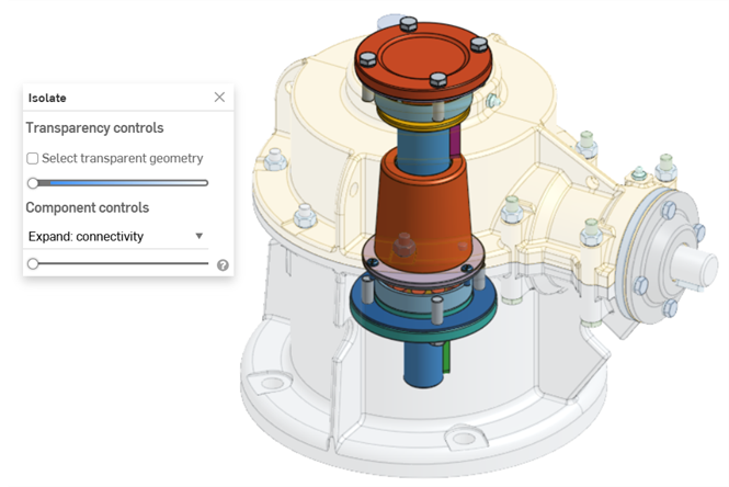
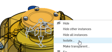
リストまたはモデルの選択を右クリックして、コンテキストメニューから [分離] を選択します。分離ダイアログが開きます。
-
透過性スライダ (透過性の制御の下) を設定します。
-
左端に設定すると、透明なジオメトリの外側のエッジのみが表示されます。選択項目の内部ジオメトリは表示されません (上図)。
-
右端に設定すると、透明なジオメトリは完全に透明になります。
-
2 つの側面の間の任意の位置に設定すると、透明なジオメトリの内部ジオメトリが表示されます (下図)。スライダを右に動かすと透過性が上がり、透明なジオメトリの不透明度が低くなります。スライダを左に動かすと透過性が下がり、透明なジオメトリがより不透明になります。
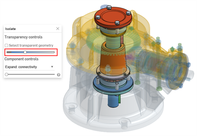
-
-
[透明ジオメトリを選択] をオンにすると、グラフィック領域でパーツ/インスタンス、点、エッジ、面、合致コネクタなどの透明ジオメトリを選択、測定、解析、編集できます (下図)。オフにすると、不透明なジオメトリのみを選択、測定、解析、編集できます。
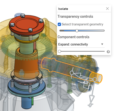
[透明ジオメトリを選択] をオンにすると、透明なパーツ/インスタンス、フォルダ、合致コネクタ、およびグループをパーツリストやインスタンスリストから選択することもできます。
-
コンポーネントの制御を使用して次のいずれかを選択します。
-
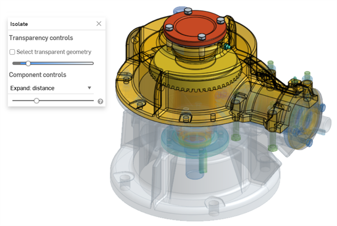
展開: 距離 - スライダを使用して、選択したパーツまたはインスタンスへの物理的な近接度に基づいて、各パーツまたはインスタンスを連続的に分離します。スライダを右に動かすと、パーツ/インスタンスがより不透明になります。
-
展開: 接続 (アセンブリのみ) - スライダを使用して、合致の接続に基づいて各インスタンスを連続的に分離します。スライダを右に動かすと、より不透明になります。
-
-
すべてのパーツの表示状態を戻すには、ダイアログの x アイコンをクリックしてダイアログを閉じます。閉じた後も、分離ダイアログで行った選択はすべて保持されます。
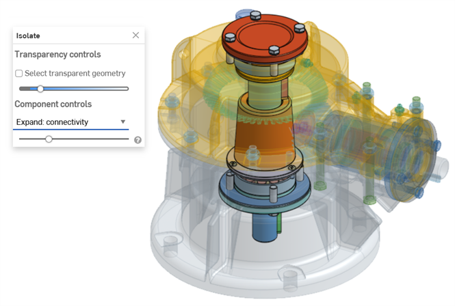
以下の例では、歯車とバルブのアセンブリの上部カバーのインスタンスが選択され、コンテキストメニューから [分離] が選択されています。
[展開: 距離] スライダを使用して、選択したカバーインスタンスへの近接度に基づいてインスタンスを連続的に分離します。
[展開: 接続] スライダを使用して、カバーインスタンスから合致接続に基づいてインスタンスを連続的に分離します。
-
カーソルを合わせたパーツまたはインスタンスを分離するには、ショートカットキー Shift+I を使用します。このコマンドは累積的に使用できます。分離ダイアログを閉じるまで、パーツを 1 つずつ、またはインスタンスごとに使用して、すべてを分離できます。パーツまたはインスタンスを複数選択して、Shift+I コマンドを選択することもできます。
-
[その他を選択] (`) キー (「1」キーの左側にあるアクサングラーブキー) を使用して、追加のエンティティを累積的に選択することもできます。
-
フォルダ全体、またはパーツまたはインスタンスのグループを分離するには、パーツ/インスタンスリストでフォルダまたはグループを右クリックし、[分離] を選択します。
-
[分離] は、インコンテキストモデリングや、断面ビューを使用する場合にも使用できます。
-
ダイアログを閉じてからもう一度開いたときも、[透過ジオメトリを選択] と透過性スライダの設定は記憶されます。
-
透過性スライダを左右に動かすと、[透過ジオメトリを選択] がオンになっていても自動的に無効 (オフ) になります。その後、スライダを動かすと自動的に再び有効 (オン) になります。
-
X アイコンで分離ダイアログを閉じる代わりに、次のいずれかを行います。
-
グラフィック領域でモデルを右クリックするか、パーツ/インスタンスリストを右クリックして、コンテキストメニューから [分離を終了] を選択します。
-
Esc (エスケープ) キーを使用します。
-
-
iOS プラットフォームでは、[展開: 距離] のみ使用できます。パーツを選択し、2 本指でタップしてコンテキストメニューを開き、[分離] を選択します。
ショートカット: Shift-t
選択した Part Studio またはアセンブリエンティティを透明にします。他のエンティティは不透明のままです。オプションには、透明な内部ジオメトリを視覚化して選択、測定、分析、編集できるようにしたり、接続性や物理的な近接度に基づいて透明な選択範囲を展開することが含まれます。
[透明にする] の使用例:
-
大規模な Part Studio やアセンブリでのエンティティの可視性を高めるため。
-
他のジオメトリに隠れているジオメトリ (点、エッジ、面、合致コネクタなど) を視覚化してタスクを実行するため。
-
関連するモデルジオメトリにアクセスする際にエンティティの検索や非表示/表示が困難または面倒な場合に、非表示/表示コマンドの代替手段として。
[透明にする] コマンドは、[分離] コマンドの逆です。
[分離] コマンドと [透明にする] コマンドは、互いに逆の働きをします。
透明にすると、選択した Part Studio またはアセンブリの要素はすべて透明になり、その他の要素はすべて不透明になります。一方、[分離] を選択すると、選択した要素は不透明になり、その他の要素はすべて透明になります。
どちらのコマンドも、大規模な Part Studio やアセンブリで要素を見やすくし、他のジオメトリに隠れている要素を視覚化するのに役立ちます。
1 つまたは複数の要素を不透明または透明にするには、Part Studio のパーツリスト、アセンブリのインスタンスリスト、またはグラフィック領域で要素を選択して右クリックし、コンテキストメニューから [分離] または [透明にする] を選択します。または、要素にカーソルを合わせ、Shift+I を押して分離するか、Shift+T を押して透明にします。要素の上にカーソルを合わせ、同じショートカットキーを使用して要素を累積的に追加します。
グラフィック領域で透明なジオメトリを選択、測定、解析、編集するには、[透明ジオメトリを選択] をオンにします。
内部ジオメトリの表示/非表示スライダを使用して透明度を調整します。
[分離] と [透明にする] の両方で、スライダは透明部分の外側のエッジと内部のジオメトリの可視性を制御します。スライダを一番左に置くと、外側のエッジは表示されたままになり、内部の形状は完全に透明になります。スライダを右に動かすと、内部の形状が表示されていきます。スライダをさらに右に動かすと、内部のジオメトリと外側の選択エッジが完全に見えなくなるまでフェードアウトします。
コンポーネントの制御を使用して、距離または接続性で拡張します。距離を拡張してスライダを右に動かすと、[分離] は連続する各パーツを不透明にし、[透明にする] は元の選択範囲への近さに基づいて透明度を調整します。接続性を拡張してスライダを右に動かすと、元の選択からの合致接続性への近さに基づいて、連続する各パーツが透明または不透明になります。接続性による拡張はアセンブリでのみ可能です。
ダイアログを閉じるか、Esc を押して終了します。
[透明ジオメトリを選択] と透過性スライダの設定は、ダイアログを閉じてから再度開くまでの間、およびドキュメントセッション間で維持されます。
[透明にする] は、パーツリスト (Part Studio)、インスタンスリスト (アセンブリ内)、または Part Studio またはアセンブリのグラフィック領域でモデルの選択を右クリックしたときのコンテキストメニューコマンドとして使用できます。
Part Studio またはアセンブリから:
-
透明にしたいエンティティを、パーツリスト、インスタンスリスト、またはグラフィック領域から選択します。これには、パーツ/インスタンス、点、エッジ、面、合致コネクタ、フォルダ、またはグループがあります。
-
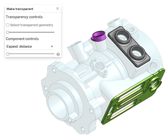
リストまたはモデルの選択を右クリックして、コンテキストメニューから [透明にする] を選択します。透明にするダイアログが開きます。
-
透過性スライダ (透過性の制御の下) を設定します。
-
左端に設定すると、透明なジオメトリの外側のエッジのみが表示されます。選択項目の内部ジオメトリは表示されません (上図)。
-
右端に設定すると、透明なジオメトリは完全に透明になります。
-
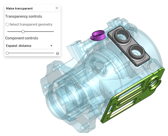
2 つの側面の間の任意の位置に設定すると、透明なジオメトリの内部ジオメトリが表示されます (下図)。スライダを右に動かすと透過性が上がり、透明なジオメトリの不透明度が低くなります。スライダを左に動かすと透過性が下がり、透明なジオメトリがより不透明になります。
-
-
[透明ジオメトリを選択] をオンにすると、グラフィック領域でパーツ/インスタンス、点、エッジ、面、合致コネクタなどの透明ジオメトリを選択、測定、解析、編集できます (下図)。オフにすると、不透明なジオメトリのみを選択、測定、解析、編集できます。
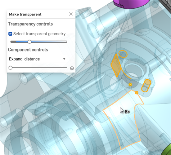
[透明ジオメトリを選択] をオンにすると、透明なパーツ/インスタンス、フォルダ、合致コネクタ、およびグループをパーツリストやインスタンスリストから選択することもできます。
-
コンポーネントの制御を使用して次のいずれかを選択します。
-
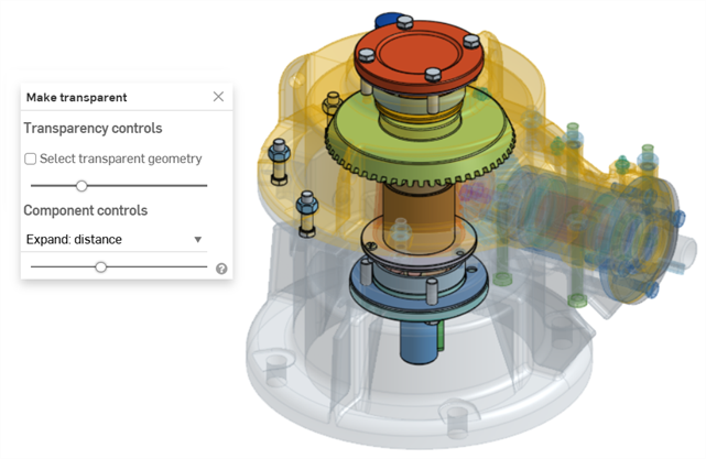
展開: 距離 - スライダを使用して、選択したパーツまたはインスタンスへの物理的な近接度に基づいて、各パーツまたはインスタンスを連続的に透明にします。スライダを右に動かすと、パーツ/インスタンスがより透明になります。
-
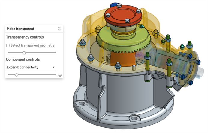
展開: 接続 (アセンブリタブのみ) - スライダを使用して、合致の接続に基づいて各インスタンスを連続的に透明にします。スライダを右に動かすと、より透明になります。
-
-
すべてのパーツまたはインスタンスの透明度を削除するには、ダイアログの x アイコンをクリックします。ダイアログを閉じた後も、透明にするダイアログで行った選択はすべて保持されます。
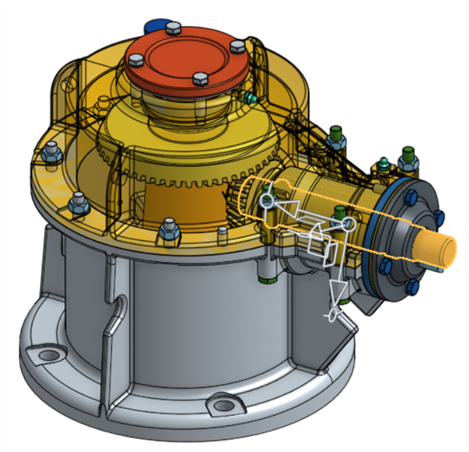
以下の例では、歯車とバルブのアセンブリのシャフトのインスタンスが選択され、コンテキストメニューから [透明にする] が選択されています。
展開: 距離スライダを使用して、選択したシャフトインスタンスへの近接度に基づいてインスタンスを透明にします。
展開: 接続スライダを使用して、シャフトインスタンスからの合致接続に基づいてインスタンスを連続的に透明にします。
-
カーソルを合わせたパーツまたはインスタンスを透明にするには、ショートカットキー Shift+T を使用します。このコマンドは累積的に使用できます。透明にするダイアログを閉じるまで、パーツを 1 つずつ、またはインスタンスごとに使用して、すべてを透明にできます。パーツまたはインスタンスを複数選択して、Shift+T コマンドを選択することもできます。
-
[その他を選択] (`) キー (「1」キーの左側にあるアクサングラーブキー) を使用して、追加のエンティティを累積的に選択することもできます。
-
パーツまたはインスタンスのフォルダ全体を透明にするには、パーツ/インスタンスリスト内のフォルダを右クリックして [透明にする] を選択します。
- [透明にする] は、インコンテキストモデリングや、断面ビューを使用する場合にも使用できます。
- ダイアログを閉じてからもう一度開いたときも、[透過ジオメトリを選択] と透過性スライダの設定は記憶されます。
-
透過性スライダを左右に動かすと、[透過ジオメトリを選択] がオンになっていても自動的に無効 (オフ) になります。その後、スライダを動かすと自動的に再び有効 (オン) になります。
-
X アイコンで透明にするダイアログを閉じる代わりに、次のいずれかを行います。
-
グラフィック領域でモデルを右クリックするか、パーツ/インスタンスリストを右クリックして、コンテキストメニューから [透明を終了] を選択します。
-
Esc (エスケープ) キーを使用します。
-
