![]()
![]()
![]()
Per facilitare il processo di assemblaggio delle istanze, Onshape fornisce alcuni comodi strumenti nel menu contestuale:
- Mostra/Nascondi
- Separa
- Rendi trasparente
Usa questi comandi per accedere alle istanze e agli accoppiamenti necessari per le attività che stai svolgendo, anziché perdere tempo cercando e spostando parti e sottoassiemi, per avere facile accesso solo alle entità che interessano.
Scelta rapida: Nascondi - y / Mostra - Maiusc+y
Mostra/Nascondi le entità Part Studio o assieme selezionate. Questi possono essere schizzi, parti/istanze, superfici, accoppiamenti, cartelle o gruppi. I comandi Mostra/Nascondi sono una serie di comandi di commutazione disponibili nel menu contestuale di un elenco delle parti in un Part Studio, nell'elenco Istanze in un assieme o nell'area grafica quando si passa il cursore del mouse su un modello.
L'opzione Mostra/Nascondi è utilizzata:
-
Per accedere meglio alle entità che potrebbero essere nascoste da altre entità (ad esempio, parti nascoste da altre parti)
-
Per mostrare tutte le entità di un tipo specificato (ad esempio, mostrare tutti gli accoppiamenti di un assieme)
-
Quando si modellano parti geometricamente dipendenti l'una dall'altra
-
Quando si effettuano modifiche in contesto.
I comandi disponibili sono:
-
Mostra/Nascondi: abilita o disabilita la visualizzazione di un'entità del modello nell'area grafica.
-
Mostra/Nascondi tutto: mostra o nasconde tutte le entità dello stesso tipo nella scheda corrente. Ad esempio, facendo clic con il pulsante destro del mouse su un'istanza nell'elenco delle istanze dell'assieme e selezionando Nascondi tutte le istanze, sono nascoste tutte le istanze dell'assieme.
-
Mostra/Nascondi altro: mostra o nasconde tutte le entità dello stesso tipo che sono diverse da quelle attualmente selezionate nella scheda corrente. Ad esempio, facendo clic con il pulsante destro del mouse su un accoppiamento in un elenco di funzioni di accoppiamento e selezionando Nascondi altri accoppiamenti, sono nascosti tutti gli accoppiamenti nell'assieme diversi da quello attualmente selezionato (o su cui hai fatto clic con il pulsante destro del mouse).
Nascondi esempio
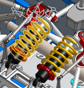
Seleziona le parti da nascondere e fai clic su Nascondi nel menu contestuale. Le parti selezionate prima di Nascondi:
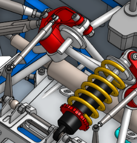
Il modello dopo Nascondi:
Esempio di nascondi altre parti
Seleziona le parti che desideri visualizzare e fai clic su Nascondi altre parti nel menu contestuale:
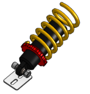
Tutte le altre parti sono nascoste tranne quelle selezionate.
-
Usa il tasto di scelta rapida y per nascondere un'entità sotto il cursore (l'entità è evidenziata al passaggio del mouse). Usa Maiusc+y per mostrare l'entità.
-
Sono disponibili strumenti aggiuntivi per isolare e rendere trasparenti le entità. Vedi Isola e rendi trasparente.
-
Selezione rettangolo funziona anche per selezionare le entità nell'area grafica.
-
Non è necessario creare un contesto per utilizzare la funzionalità Mostra/Nascondi.
Scorciatoia: Maiusc+i
Isola mantiene opache tutte le entità Part Studio o Assieme selezionate, mentre rende trasparenti le altre entità. Le opzioni includono la visualizzazione della geometria interna trasparente in modo che sia possibile selezionarla, misurarla, analizzarla e modificarla, e l'espansione della selezione isolata in base alla connettività o alla prossimità fisica.
Isola è usato:
-
Per migliorare la visibilità delle entità in Part Studio/assiemi di grandi dimensioni.
-
Per visualizzare ed eseguire operazioni sulla geometria (ad esempio, punti, bordi, facce, mate connector) occlusi da altre geometrie.
-
In alternativa ai comandi Mostra/Nascondi, nei casi in cui trovare e nascondere/mostrare le entità per accedere alla geometria del modello pertinente risulta un'operazione difficile o ripetitiva.
Il comando Isola è l'inverso del comando Rendi trasparente.
I comandi Isola e Rendi trasparente sono l'uno l'opposto dell'altro.
Rendi trasparente trasforma in trasparenti gli elementi del Part Studio o dell'assieme selezionati mantenendo opachi tutti gli altri elementi, mentre Isola mantiene opachi gli elementi selezionati e rende trasparenti tutti gli altri elementi.
Entrambi i comandi migliorano la visibilità degli elementi in Part Studio e Assiemi di grandi dimensioni e aiutano a visualizzare gli elementi occlusi da altre geometrie.
Per rendere opachi o trasparenti uno o più elementi, effettua selezioni all'interno dell'elenco delle parti del Part Studio, dell'elenco delle istanze dell'assieme o dell'area grafica, quindi fai clic con il pulsante destro del mouse e seleziona Isola o Rendi trasparente nel menu contestuale. In alternativa passa il cursore del mouse su un elemento e premi Maiusc+i per isolare o Maiusc+t per rendere trasparente. Posiziona il cursore sugli elementi e usa gli stessi tasti di scelta rapida per aggiungere elementi cumulativamente.
Seleziona l'opzione Seleziona geometria trasparente per selezionare, misurare, analizzare e modificare la geometria trasparente nell'area grafica.
Utilizza il cursore Mostra o nascondi la geometria interna per regolare la trasparenza.
Sia in Isola che in Rendi trasparente, il cursore controlla la visibilità dei bordi esterni della trasparenza e della geometria interna della trasparenza. Quando il cursore è completamente a sinistra, i bordi esterni rimangono visibili mentre la geometria interna è completamente trasparente. Quando il cursore si sposta verso destra, la geometria interna è resa visibile. Quando il cursore viene spostato più a destra, la geometria interna e i bordi di selezione esterni si attenuano, fino a diventare entrambi completamente invisibili.
Usa i comandi di Componente per espandere in base alla distanza o alla connettività. Quando espandi in base alla distanza e sposti il cursore verso destra, Isola rende opaca ogni parte successiva mentre Rendi trasparente regola la trasparenza in base alla vicinanza alla selezione originale. Quando espandi in base alla connettività, spostando il cursore verso destra rendi ogni parte successiva trasparente o opaca in base alla vicinanza alle connessioni di accoppiamento rispetto alla selezione originale. L'espansione tramite connettività è disponibile solo in un assieme.
Chiudi la finestra di dialogo o premi Esc per uscire.
Le impostazioni del cursore Seleziona geometria trasparente e trasparenza sono conservate quando esci e rientri nella finestra di dialogo e tra le sessioni del documento.
Isola è disponibile come comando del menu contestuale nell'elenco delle parti (in un Part Studio), nell'elenco delle istanze (in un assieme) o nell'area grafica di un Part Studio o assieme quando si fa clic con il pulsante destro del mouse su una selezione del modello.
In un Part Studio o un assieme:
-
Seleziona le entità da isolare dall'elenco delle parti o delle istanze o nell'area grafica. Queste possono essere parti/istanze, punti, bordi, facce, mate connector, cartelle o gruppi.
-
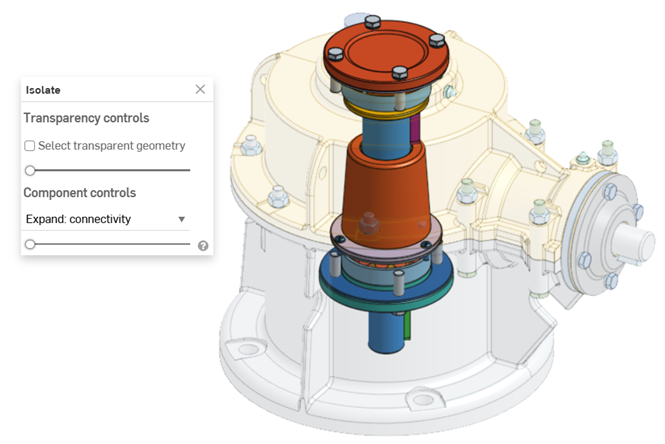
Fai clic con il pulsante destro del mouse sull'elenco o sulla selezione del modello e seleziona Isola nel menu contestuale. Si apre la finestra di dialogo Isola:
-
Imposta il Cursore trasparenza (sotto i comandi di Trasparenza):
-
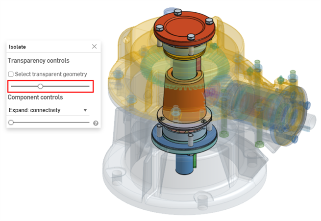
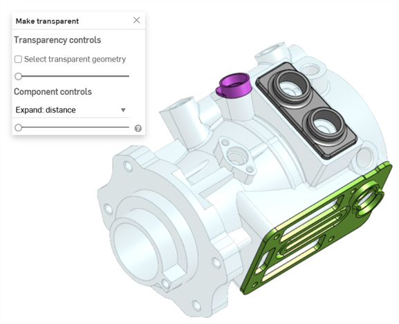
Quando il cursore è completamente a sinistra, sono visualizzati solo i bordi esterni della geometria trasparente. La geometria interna della selezione non è visualizzata (sopra).
-
Quando il cursore è a destra, la geometria trasparente è completamente trasparente.
-
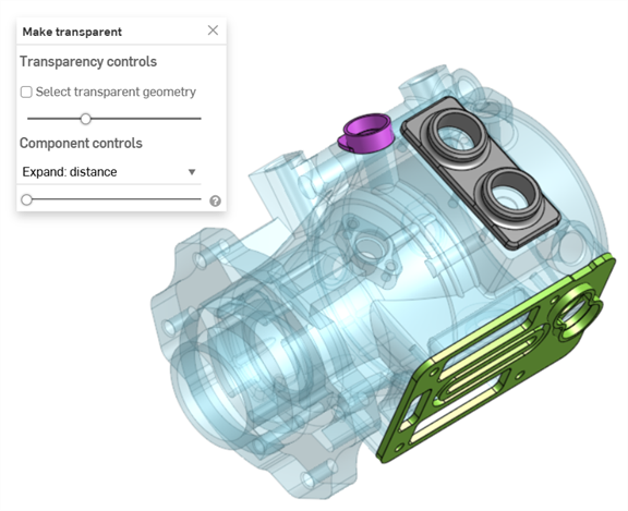
Quando il cursore è posizionato in un punto qualsiasi tra i due lati, è visualizzata la geometria interna della geometria trasparente (di seguito). Spostando il cursore verso destra si aumenta la trasparenza, rendendo la geometria trasparente meno opaca. Spostando il cursore verso sinistra si riduce la trasparenza, rendendo la geometria trasparente più opaca.
-
-
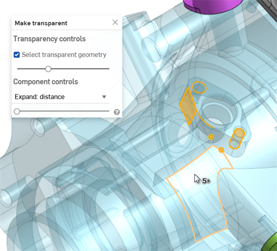
Se è selezionata l'opzione Seleziona geometria trasparente, è possibile selezionare, misurare, analizzare e modificare la geometria trasparente come parti/istanze, punti, bordi, facce e mate connector nell'area grafica (visualizzata di seguito). Se l'opzione è deselezionata, è possibile selezionare, misurare, analizzare e modificare solo la geometria non trasparente.
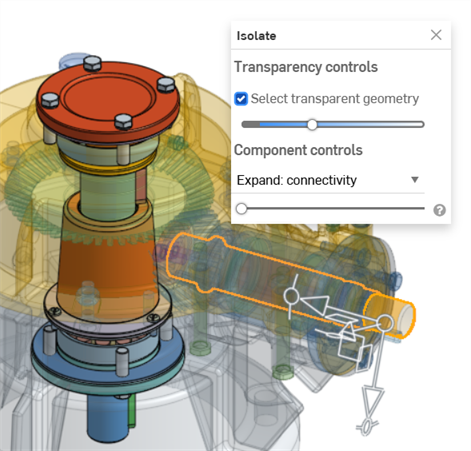
Quando l'opzione Seleziona geometria trasparente è selezionata, è possibile selezionare parti/istanze, cartelle, mate connector e gruppi trasparenti anche nell'elenco delle parti o delle istanze.
-
Utilizza i comandi Componente per selezionare una delle seguenti opzioni:
-
Espandi: distanza: usa il cursore per isolare ogni parte o istanza successiva in base alla sua vicinanza fisica alle parti o alle istanze selezionate. Lo spostamento del cursore verso destra rende più parti/istanze non trasparenti (opache).
-
Espandi: connettività (solo assieme): usa il cursore per isolare ogni istanza successiva in base alla sua connettività di accoppiamento. Spostando il cursore verso destra, più istanze diventano non trasparenti (opache).
-
-
Fai clic sull'icona x nella finestra di dialogo per chiuderla e riportare tutte le parti allo stato visibile. Dopo l'uscita, tutte le selezioni effettuate nella finestra di dialogo Isola sono mantenute.
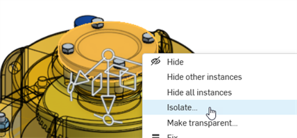
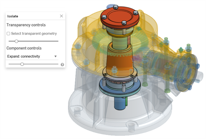
Nell'esempio seguente è selezionata l'istanza del coperchio superiore di un assieme di ingranaggi e valvole e l'opzione Isola è selezionata nel menu contestuale:
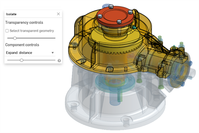
Il cursore Espandi: distanza è utilizzato per isolare le istanze in successione in base alla loro vicinanza all'istanza di copertina selezionata:
Il cursore Espandi: connettività è utilizzato per isolare le istanze in base a connessioni di accoppiamento successive nell'istanza del coperchio:
-
Utilizza il tasto di scelta rapida Maiusc+i per isolare parti o istanze sotto il cursore. Questo comando è cumulativo: puoi usarlo parte dopo parte o istanza dopo istanza per isolarli tutti finché non esci dalla finestra di dialogo Isola. È inoltre possibile selezionare più parti o istanze e quindi selezionare il comando Maiusc+i.
-
Il tasto Seleziona altro (`) (tasto con accento grave, a sinistra del tasto 1) è utilizzabile anche per selezionare cumulativamente entità aggiuntive.
-
Per isolare un'intera cartella o gruppo di parti o istanze, fai clic con il pulsante destro del mouse sulla cartella o sul gruppo nell'elenco delle parti o delle istanze e seleziona Isola.
-
Isola è disponibile anche quando si modella in contesto e si utilizza Vista in sezione.
-
Le impostazioni del cursore Seleziona geometria trasparente e Trasparenza sono ricordate se si esce dalla finestra di dialogo e si entra nuovamente.
-
Se l'opzione Seleziona geometria trasparente è selezionata, spostando il cursore Trasparenza completamente a sinistra o a destra lo si disattiva automaticamente (deselezionato). Se successivamente sposti il cursore, questo si riattiva automaticamente (selezionato).
-
Come alternativa a effettuare l'uscita dalla finestra di dialogo Isola tramite l'icona x, puoi:
-
fare clic con il pulsante destro del mouse sul modello nell'area grafica o fare clic con il pulsante destro del mouse sull'elenco delle parti/delle istanze e selezionare Esci da Isola nel menu contestuale
-
fare clic sul tasto Esc (escape)
-
-
Sulle piattaforme iOS è disponibile solo Espandi: distanza. Seleziona la parte, tocca con due dita per aprire il menu contestuale, quindi seleziona Isola.
Tasto di scelta rapida: Maiusc+F
Rende trasparenti le entità Part Studio o Assieme selezionate. Le altre entità rimangono opache. Le opzioni includono la visualizzazione della geometria interna trasparente in modo che possa essere selezionata, misurata, analizzata e modificata e l'espansione della selezione trasparente in base alla connettività o alla prossimità fisica.
Si usa Rendi transparente:
-
Per migliorare la visibilità delle entità in Part Studio/assiemi di grandi dimensioni.
-
Per visualizzare ed eseguire operazioni sulla geometria (ad esempio, punti, bordi, facce, mate connector) occlusi da altre geometrie.
-
In alternativa ai comandi Mostra/Nascondi, nei casi in cui trovare e nascondere/mostrare le entità per accedere alla geometria del modello pertinente risulta un'operazione difficile o ripetitiva.
Il comando Rendi trasparente è l'inverso del comando Isola.
I comandi Isola e Rendi trasparente sono l'uno l'opposto dell'altro.
Rendi trasparente trasforma in trasparenti gli elementi del Part Studio o dell'assieme selezionati mantenendo opachi tutti gli altri elementi, mentre Isola mantiene opachi gli elementi selezionati e rende trasparenti tutti gli altri elementi.
Entrambi i comandi migliorano la visibilità degli elementi in Part Studio e Assiemi di grandi dimensioni e aiutano a visualizzare gli elementi occlusi da altre geometrie.
Per rendere opachi o trasparenti uno o più elementi, effettua selezioni all'interno dell'elenco delle parti del Part Studio, dell'elenco delle istanze dell'assieme o dell'area grafica, quindi fai clic con il pulsante destro del mouse e seleziona Isola o Rendi trasparente nel menu contestuale. In alternativa passa il cursore del mouse su un elemento e premi Maiusc+i per isolare o Maiusc+t per rendere trasparente. Posiziona il cursore sugli elementi e usa gli stessi tasti di scelta rapida per aggiungere elementi cumulativamente.
Seleziona l'opzione Seleziona geometria trasparente per selezionare, misurare, analizzare e modificare la geometria trasparente nell'area grafica.
Utilizza il cursore Mostra o nascondi la geometria interna per regolare la trasparenza.
Sia in Isola che in Rendi trasparente, il cursore controlla la visibilità dei bordi esterni della trasparenza e della geometria interna della trasparenza. Quando il cursore è completamente a sinistra, i bordi esterni rimangono visibili mentre la geometria interna è completamente trasparente. Quando il cursore si sposta verso destra, la geometria interna è resa visibile. Quando il cursore viene spostato più a destra, la geometria interna e i bordi di selezione esterni si attenuano, fino a diventare entrambi completamente invisibili.
Usa i comandi di Componente per espandere in base alla distanza o alla connettività. Quando espandi in base alla distanza e sposti il cursore verso destra, Isola rende opaca ogni parte successiva mentre Rendi trasparente regola la trasparenza in base alla vicinanza alla selezione originale. Quando espandi in base alla connettività, spostando il cursore verso destra rendi ogni parte successiva trasparente o opaca in base alla vicinanza alle connessioni di accoppiamento rispetto alla selezione originale. L'espansione tramite connettività è disponibile solo in un assieme.
Chiudi la finestra di dialogo o premi Esc per uscire.
Le impostazioni del cursore Seleziona geometria trasparente e trasparenza sono conservate quando esci e rientri nella finestra di dialogo e tra le sessioni del documento.
Rendi trasparente è disponibile come comando del menu contestuale nell'elenco delle parti (in un Part Studio), nell'elenco delel istanze (in un Assieme) o nell'area grafica del Part Studio o dell'assieme quando fai clic con il pulsante destro del mouse su una selezione del modello.
In un Part Studio o un assieme:
-
Seleziona le entità che vuoi rendere trasparenti nell'elenco delle parti o delle istanze o nell'area grafica. Queste possono essere parti/istanze, punti, bordi, facce, mate connector, cartelle o gruppi.
-
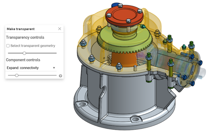
Fai clic con il pulsante destro del mouse sull'elenco o sulla selezione del modello e seleziona Rendi trasparente nel menu contestuale. Si apre la finestra di dialogo Rendi trasparente:
-
Imposta il Cursore trasparenza (sotto i comandi di Trasparenza):
-
Quando il cursore è completamente a sinistra, sono visualizzati solo i bordi esterni della geometria trasparente. La geometria interna della selezione non è visualizzata (sopra).
-
Quando il cursore è a destra, la geometria trasparente è completamente trasparente.
-
Quando il cursore è posizionato in un punto qualsiasi tra i due lati, è visualizzata la geometria interna della geometria trasparente (di seguito). Spostando il cursore verso destra si aumenta la trasparenza, rendendo la geometria trasparente meno opaca. Spostando il cursore verso sinistra si riduce la trasparenza, rendendo la geometria trasparente più opaca.
-
-
Se è selezionata l'opzione Seleziona geometria trasparente, è possibile selezionare, misurare, analizzare e modificare la geometria trasparente come parti/istanze, punti, bordi, facce e mate connector nell'area grafica (visualizzata di seguito). Se l'opzione è deselezionata, è possibile selezionare, misurare, analizzare e modificare solo la geometria non trasparente.
Quando l'opzione Seleziona geometria trasparente è selezionata, è possibile selezionare parti/istanze, cartelle, mate connector e gruppi trasparenti anche nell'elenco delle parti o delle istanze.
-
Utilizza i comandi Componente per selezionare una delle seguenti opzioni:
-
Espandi: distanza: usa il cursore per rendere trasparente ogni parte o istanza successiva in base alla sua vicinanza fisica alle parti o alle istanze selezionate. Spostando il cursore verso destra si rendono trasparenti più parti/istanze.
-
Espandi: connettività (solo scheda Assieme): usa il cursore per rendere trasparente ogni istanza successiva in base alla relativa connettività accoppiamento. Spostando il cursore verso destra si rendono trasparenti più istanze.
-
-
Fai clic sull'icona x nella finestra di dialogo per rimuovere la trasparenza di tutte le parti o istanze. Dopo l'uscita, tutte le selezioni effettuate nella finestra di dialogo Rendi trasparente sono mantenute.
Nell'esempio seguente, è selezionata l'istanza dell'albero di un assieme ingranaggio e valvola e l'opzione Rendi trasparente è selezionata nel menu contestuale:
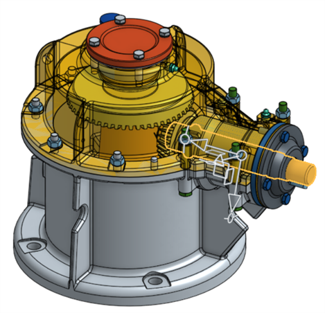
Il cursore Espandi: distanza è utilizzato per rendere trasparenti le istanze in base alla loro vicinanza all'istanza dell'albero selezionata:

Il cursore Espandi: connettività è utilizzato per rendere trasparenti le istanze in base alle successive connessioni di accoppiamento dall'istanza dell'albero:
-
Utilizza il tasto di scelta rapida Maiusc+t per rendere trasparente una parte o un'istanza sotto il cursore. Questo comando è cumulativo: puoi usarlo parte dopo parte o istanza dopo istanza per mantenerli tutti trasparenti fino alla chiusura della finestra di dialogo Rendi trasparente. È inoltre possibile selezionare più parti o istanze e quindi selezionare il comando Maiusc+t.
-
Il tasto Seleziona altro (`) (tasto con accento grave, a sinistra del tasto 1) è utilizzabile anche per selezionare cumulativamente entità aggiuntive.
-
Per rendere trasparente un'intera cartella di parti o istanze, fai clic con il pulsante destro del mouse sulla cartella nell'elenco delle parti o delle istanze e seleziona Rendi trasparente.
- L'opzione Rendi trasparente è disponibile anche quando si modella in contesto e si utilizza Vista in sezione.
- Le impostazioni del cursore Seleziona geometria trasparente e Trasparenza sono ricordate se si esce dalla finestra di dialogo e si entra nuovamente.
-
Se l'opzione Seleziona geometria trasparente è selezionata, spostando il cursore Trasparenza completamente a sinistra o a destra lo si disattiva automaticamente (deselezionato). Se successivamente sposti il cursore, questo si riattiva automaticamente (selezionato).
-
Come alternativa a effettuare l'uscita dalla finestra di dialogo Rendi trasparente tramite l'icona x, puoi:
-
Fai clic con il pulsante destro del mouse sul modello nell'area grafica oppure fai clic con il pulsante destro del mouse sull'elenco delle parti/delle istanze e seleziona Termina rendi trasparente nel menu contestuale
-
fare clic sul tasto Esc (escape)
-