Définition basée sur un modèle (MBD)
![]()
![]()
![]()
Disponible dans : Part Studio
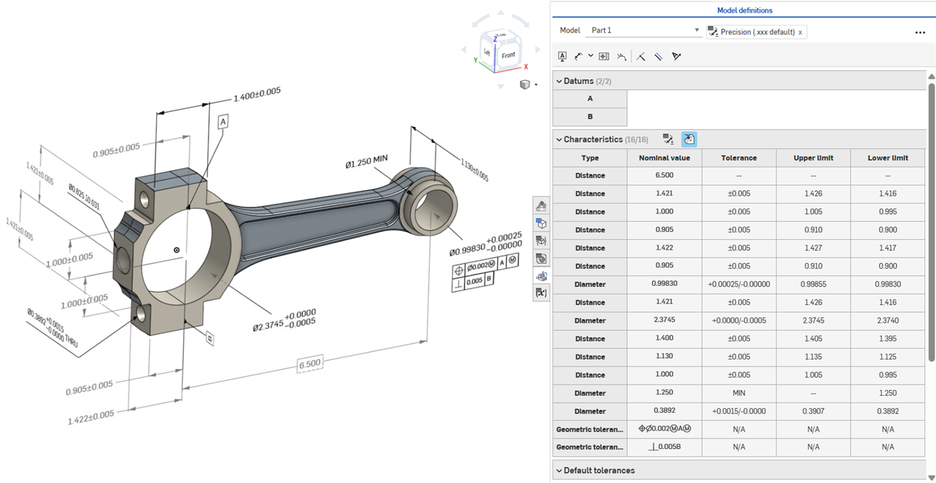
La définition basée sur un modèle (MBD) fait référence au processus de cotation et d'annotation du modèle dans le Part Studio afin que le modèle contienne toutes les données nécessaires à la définition d'un produit. Avec MBD, le modèle devient l'autorité source qui gère toutes les activités d'ingénierie. Ce modèle peut également être utilisé en aval par les fournisseurs et dans l'ensemble des organisations.
Les données MBD fonctionnent conjointement avec les options de tolérance, où les cotes des esquisses et des fonctions sont rendues tolérantes, et avec le tableau d'inspection, où les données MBD peuvent être consultées, ajoutées et exportées pour chaque pièce dans un Part Studio.
La MBD n'est pas destinée à remplacer les dessins. Elle sert à capturer et à étendre les informations de fabrication des produits (PMI) d'un modèle et les informations de l'entreprise basées sur les modèles (MBE) pour une utilisation supplémentaire ou alternative en aval.
Quelques fonctions de la MBD :
-
Métadonnées des cotes et annotations intégrées au modèle dans le Part Studio
-
Amélioration de la collaboration en temps réel sur le modèle dans le Part Studio
-
Fourniture d'une source unique d'informations aux ingénieurs dans toute l'organisation
-
Lien vers les processus en aval, tels que l'inspection par machine à mesurer tridimensionnelle (CMM)
Les cotes principales des fonctions et esquisses MBD peuvent être modifiées directement depuis la zone graphique.
Les informations de fabrication des produits peuvent être modifiées dans la zone graphique lorsque le tableau d'inspection est ouvert, ainsi que dans les esquisses et les fonctions où elles ont été définies à l'origine.
Modifiez les tolérances en double-cliquant sur la cote dans la zone graphique. Si la cote fait référence à la liste des fonctions, Onshape ouvre l'esquisse ou la fonction pour la modifier. Si la cote a été créée à l'aide de la barre d'outils Annotation, modifiez-la depuis la zone graphique. À mesure que le modèle et les tolérances changent, le tableau d'inspection est mis à jour en temps réel.
Dans le tableau des caractéristiques, filtrez les lignes à l'aide de deux boutons à bascule. Dans un premier temps, les annotations avec des tolérances par défaut sont affichées, tandis que les annotations issues de la géométrie dérivée sont masquées. Les annotations dérivées ne peuvent être mises à jour qu'en modifiant la source.
Utilisez le surlignage croisé pour identifier et localiser rapidement les références de modèles associées. Passez la souris sur les cellules du tableau d'inspection pour mettre en surbrillance la pièce référencée, les faces, les fonctions et les annotations associées dans la zone graphique. Sélectionnez une annotation dans la zone graphique ou cliquez sur une cellule Datum ou Type pour que le surlignage reste visible.
Supprimez une annotation en la sélectionnant dans la zone graphique et en appuyant sur Supprimer. La suppression d'une annotation faisant référence à la liste des fonctions supprime les options de tolérance de la cote d'esquisse ou de la valeur de la fonction, et supprime la ligne du tableau des caractéristiques. La suppression d'une annotation placée dans la barre d'outils d'annotations la supprime du tableau. Les annotations dérivées ne peuvent pas être supprimées.
-
Ouvrez le panneau d'inspection (
 ) pour afficher les cotes MBD dans les zones graphiques (image de gauche ci-dessous).
 -
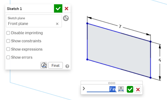
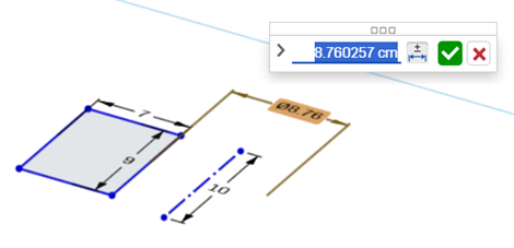
Double-cliquez sur la cote principale associée à une esquisse (image de droite ci-dessous) :
La boîte de dialogue contextuelle Cote s'ouvre avec le contexte placé sur la valeur de la cote. Simultanément, la boîte de dialogue Esquisse s'ouvre :
-
À l'aide du clavier, saisissez une valeur numérique ou utilisez les flèches haut/bas pour incrémenter la valeur dans la boîte de dialogue contextuelle Cote. Au fur et à mesure que cette valeur est ajustée, l'esquisse est mise à jour de manière dynamique.
Si vous saisissez une valeur sous forme numérique, appuyez sur la touche Tab pour voir la mise à jour de la valeur de l'esquisse.
-
Appuyez sur Entrée sur le clavier ou cliquez sur la coche (
 ) dans la boîte de dialogue contextuelle Cote pour fermer cette boîte de dialogue :
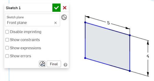
-
Cliquez sur la coche (
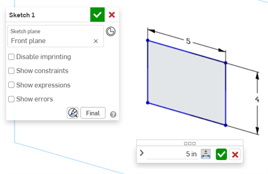
) dans la boîte de dialogue Esquisse pour accepter la nouvelle valeur de l'esquisse.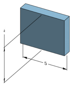
Cote de l'esquisse modifiée ajustant la cote du modèle
-
Ouvrez le panneau d'inspection (
) pour afficher les cotes MBD dans les zones graphiques (image de gauche ci-dessous). -
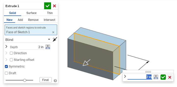
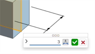
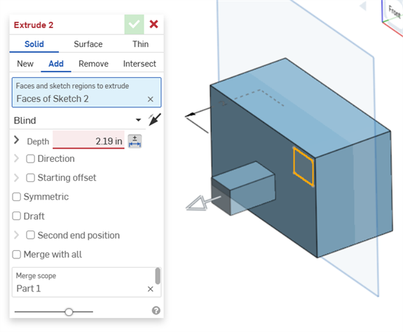
Double-cliquez sur la cote principale associée à une fonction (image de droite ci-dessous) :
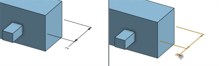
La boîte de dialogue contextuelle Cote s'ouvre avec le contexte placé sur la valeur de la cote. Simultanément, la boîte de dialogue de la fonction associée s'ouvre (Extruder dans cet exemple) :
-
À l'aide du clavier, saisissez une valeur numérique ou utilisez les flèches haut/bas pour incrémenter la valeur dans la boîte de dialogue contextuelle Cote. Au fur et à mesure que cette valeur est ajustée, le modèle et la valeur de la boîte de dialogue Fonction sont mis à jour de manière dynamique.
Si vous saisissez une valeur sous forme numérique, appuyez sur la touche Tab pour voir la valeur mise à jour dans la boîte de dialogue Fonction.
-
Appuyez sur Entrée sur le clavier ou cliquez sur la coche (
) dans la boîte de dialogue contextuelle Cote pour fermer cette boîte de dialogue :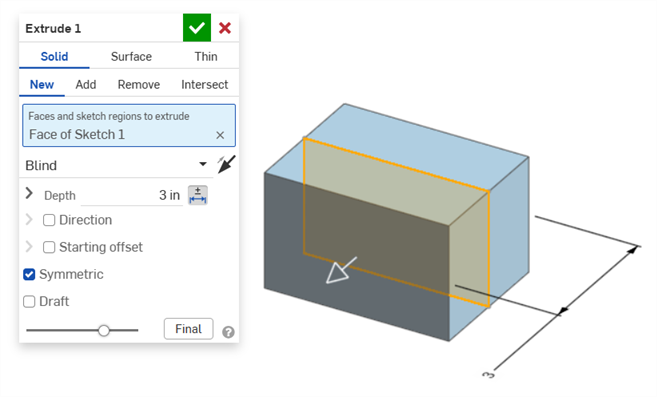
-
Appuyez à nouveau sur Entrée sur le clavier ou cochez la case de la boîte de dialogue Fonction (
) pour fermer cette boîte de dialogue :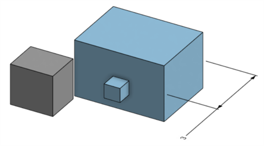
Cote de fonction modifiée ajustant la cote du modèle
Pour supprimer une annotation :
-
Sélectionnez l'annotation dans la zone graphique.
-
Appuyez sur la touche Suppr..
-
L'annotation est supprimée de la zone graphique et du tableau d'inspection.
Si l'annotation concerne une cote d'esquisse ou de fonction :
-
Les valeurs des options de tolérance de la cote sont supprimées.
-
L'icône des options de tolérance (
 ) est désélectionnée.
 -
La valeur de la cote dans la boîte de dialogue Esquisse ou Fonction n'est pas supprimée.
-
Les annotations ne peuvent pas être supprimées si :
-
L'annotation est dérivée.
-
L'annotation est créée dans une fonction personnalisée où le paramètre est rendu tolérant mais où le bouton de tolérance n'est pas disponible pour les saisies par l'utilisateur.
Dans les deux cas, le message suivant s'affiche :

-
Les cotes pilotées ne peuvent pas être modifiées. Un double-clic sur une cote pilotée ouvre la boîte de dialogue contextuelle Cote, mais les valeurs dans cette boîte de dialogue ne peuvent pas être modifiées.
-
Les cotes dérivées ne peuvent pas être modifiées. Un double-clic sur une cote principale ou pilotée à partir d'une pièce dérivée n'ouvre pas la boîte de dialogue contextuelle Cote.
-
Pour annuler et sortir de la boîte de dialogue contextuelle Cote, appuyez sur la touche Échap. Dans le cas d'une modification de cote de fonction, la boîte de dialogue contextuelle Cote et la boîte de dialogue Fonction se ferment simultanément. Dans le cas d'une modification de cote d'esquisse, seule la boîte de dialogue contextuelle Cote se ferme. La boîte de dialogue Esquisse doit être fermée manuellement (en cliquant sur l'icône x).
-
Autre méthode : lorsque les boîtes de dialogue contextuelles Fonction et Cote sont ouvertes, la valeur de la boîte de dialogue Fonction peut être sélectionnée et modifiée, ce qui met à jour dynamiquement la boîte de dialogue contextuelle Cote et le modèle. Une fois cette modification réalisée, le fait d'appuyer sur Entrée ferme simultanément la boîte de dialogue Fonction et la boîte de dialogue contextuelle Cote.
-
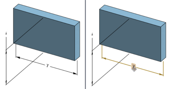
L'emplacement de la cote du modèle et celui de la cote d'esquisse correspondante ne sont pas liés. Ils sont indépendants :
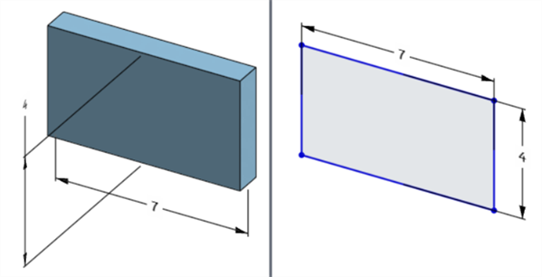
La cote de largeur du modèle est située en dessous du modèle (à gauche) mais au-dessus de l'esquisse (à droite)
-
En mode Mettre en pause la regénération, la cote du modèle ne peut être ni modifiée ni supprimée. Cependant, vous pouvez toujours modifier la fonction ou activer ou désactiver la tolérance d'une cote. Les modifications prennent effet lorsque vous cliquez sur la coche Regénérer les fonctions et quitter sur la bannière Regénération mise en pause.
-
Les configurations fonctionnent comme attendu. Cependant, la cote de la boîte de dialogue contextuelle Cote n'est pas entourée d'un contour orange en pointillés pour indiquer qu'elle est configurée. Les cotes d'esquisse configurées ne peuvent pas être modifiées.
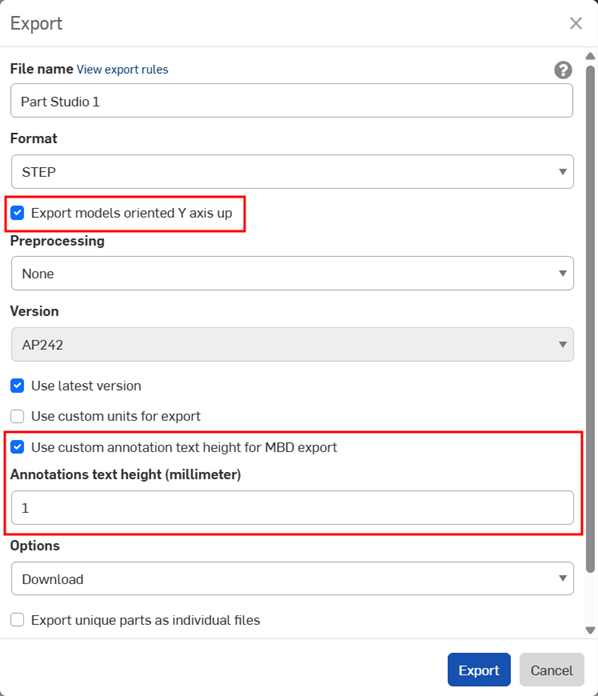
Les données MBD peuvent être exportées au format de fichier STEP lors de l'exportation de pièces. Les paramètres suivants sont recommandés :
Les données MBD ne sont pas exportées pour les pièces composites fermées. Cet avertissement s'affiche lors de l'exportation dans la boîte de dialogue d'exportation si le document est ouvert. Cependant, si une pièce est sélectionnée et exportée depuis la liste des résultats d'un document de recherche avancée, l'avertissement ne s'affiche pas, mais les données MBD ne sont toujours pas exportées.
-
Activez la case à cocher Exporter les modèles avec l'axe Y vers le haut.
-
En fonction de la taille de votre modèle, vous devrez peut-être activer l'option Utiliser une hauteur de texte d'annotation personnalisée pour l'exportation MBD et sélectionner une hauteur de texte d'annotation appropriée qui corresponde à la taille de votre modèle.
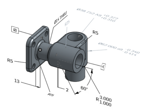
Modèle original dans Onshape
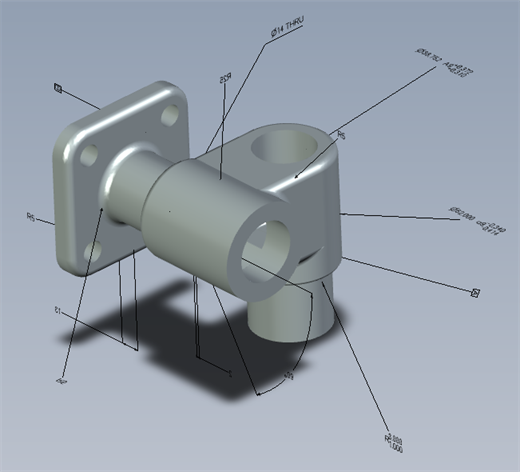
Modèle exporté avec l'option « Utiliser une hauteur de texte d'annotation personnalisée pour l'exportation MBD » désactivée
Modèle exporté avec l'option « Utiliser une hauteur de texte d'annotation personnalisée pour l'exportation MBD » activée et réglée sur 10 mm.
Une fois exportées, les tolérances géométriques comportant plusieurs cadres de tolérance associent le texte supérieur au cadre supérieur et le texte inférieur au cadre inférieur.
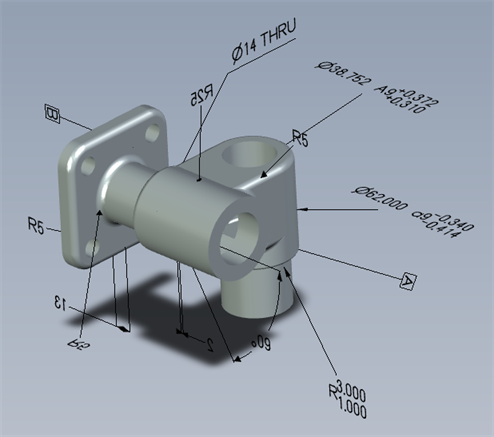
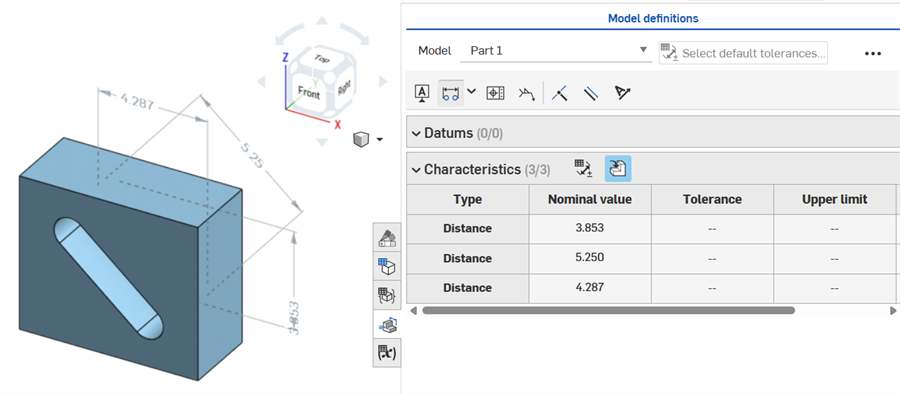
Voici des exemples de MBD utilisant des tolérances de fonctions et de cotes :
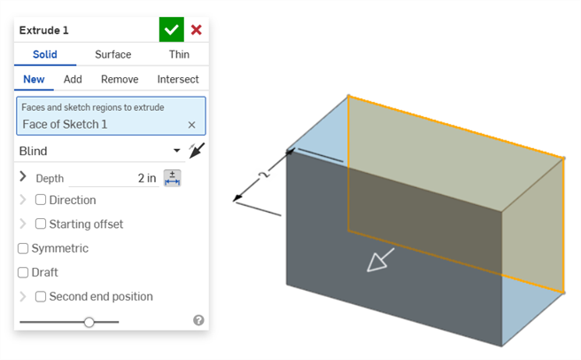
Cote de profondeur :
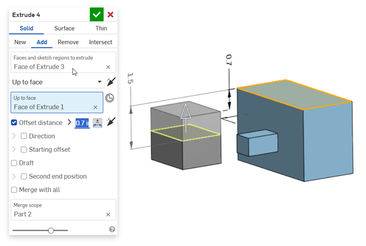
Cote de distance de décalage (avec une pièce composite) :
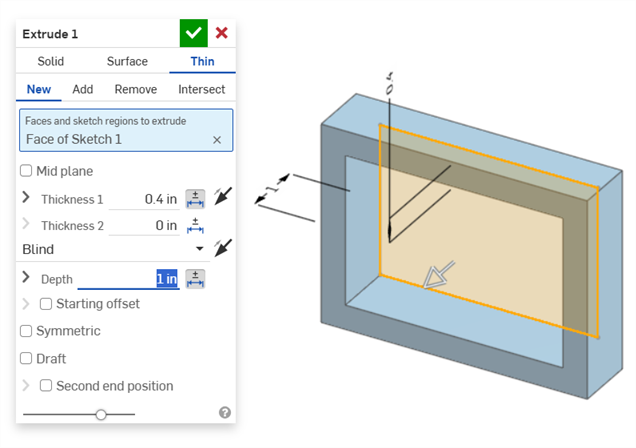
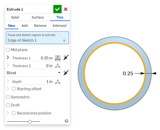
Extrusion fine (cotes de l'épaisseur 1 et de la profondeur) :
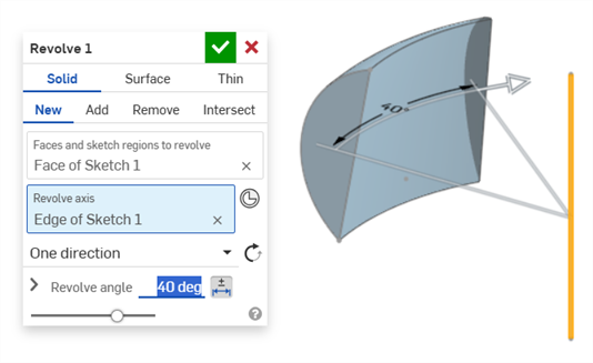
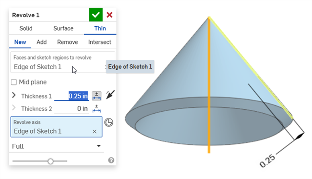
Pivoter (cote de angle de révolution) :
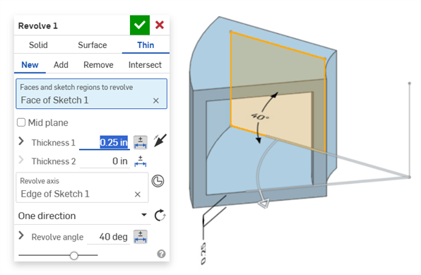
Pivoter (cote de l'épaisseur 1 et de l'angle de révolution) :
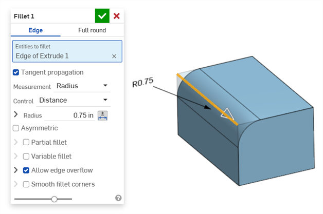
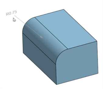
Congé (cote de rayon) :
Création d'une cote de congé pilotée avec l'outil Cote de congé du tableau d'inspection sur la barre d'outils Annotation :
L'outil Cote du panneau d'inspection (![]() ) utilise toujours des tolérances par défaut linéaires ou angulaires. La cotation d'une face filetée à l'aide de celui-ci applique un type de tolérance linéaire par défaut. C'est pourquoi il est recommandé d'appliquer les tolérances de congé depuis la boîte de dialogue de la fonction Congé (pour une cote principale), ou d'utiliser la cote de congé depuis le panneau d'inspection (pour une cote pilotée).
) utilise toujours des tolérances par défaut linéaires ou angulaires. La cotation d'une face filetée à l'aide de celui-ci applique un type de tolérance linéaire par défaut. C'est pourquoi il est recommandé d'appliquer les tolérances de congé depuis la boîte de dialogue de la fonction Congé (pour une cote principale), ou d'utiliser la cote de congé depuis le panneau d'inspection (pour une cote pilotée).
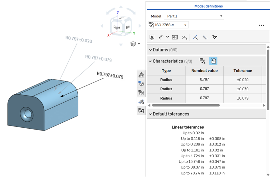
Cotation d'une face de congé, annotée dans le sens horaire : en utilisant l'outil de cote (pilotée ; annotée en gris), en utilisant l'outil Cote de congé (pilotée ; annotée en gris) et en rendant tolérante la valeur du rayon de la fonction Congé (principale ; annotée en noir). Les 3 cotes sont répertoriées dans la table des caractéristiques.
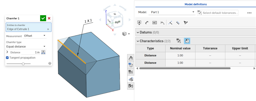
Un chanfrein est défini comme la distance par rapport à l'angle ou la distance entre une face et une arête. Les cotes de la largeur du chanfrein sont spécifiées comme la distance entre une arête et l'Intersection virtuelle. L'affichage pour les intersections virtuelles est ajouté à l'arête cotée, incluant une courbe en pointillés.
-
Les tolérances ne sont pas désactivées lorsqu'une mesure de tangente est utilisée, car elles peuvent fonctionner dans certains cas, notamment en tenant compte de la tolérance spécifiée.
-
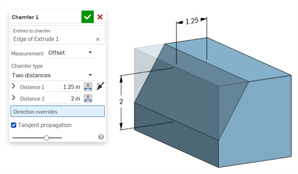
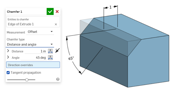
Dans les situations où deux mesures de chanfrein sont utilisées (deux distances, ou distance et angle), l'utilisateur n'a pas à créer de tolérances pour les deux. Les tolérances peuvent être ajoutées à un seul paramètre, si nécessaire.
La sélection du type Chanfrein à distance égale affiche deux valeurs de tolérance de distance, qui sont reflétées dans le tableau, même s'il n'y a qu'une seule option de tolérance de distance dans la boîte de dialogue :
Exemple avec deux distances :
Exemple avec distance et angle :
Dans les cas où le chanfrein crée une distance variable (par exemple, si le chanfrein est appliqué sur la face d'un cylindre perpendiculairement à un autre cylindre), essayez de sélectionner l'option de tangence pour la mesure, afin d'uniformiser la distance le long de l'arête :
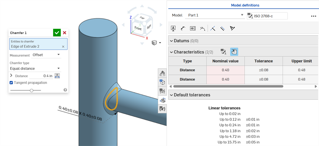
Chanfrein non uniforme utilisant une mesure de décalage affichant une erreur de valeur nominale.
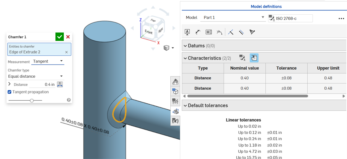
Un chanfrein uniforme utilisant une mesure de tangence donne une valeur nominale sans erreur.
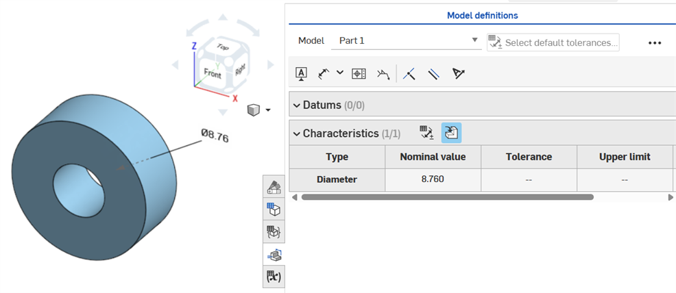
Si une tolérance est attribuée à une fonction de perçage, elle peut être affichée dans le tableau d'inspection.
N'oubliez pas :
-
Les cotes des perçages ne sont visibles que sous forme de lignes dans le tableau d'inspection. Aucune cote n'est placée dans la zone graphique, afin de ne pas surcharger la zone graphique de légendes.
-
Pour que les cotes des perçages soient visibles dans le tableau d'inspection, une autre légende (un datum, par exemple) doit être placée sur la pièce.
-
Un seul jeu de cotes (diamètre, distance et/ou angle) est indiqué par fonction de perçage. Les perçages répétés ou additionnels correspondant à la même fonction ne sont pas cotés séparément.
-
La cote personnalisée de l'angle de pointe n'est pas prise en charge actuellement et ne crée pas de ligne dans le tableau d'inspection.
-
Le surlignage croisé fonctionne comme suit :
-
La distance (profondeur) n'est pas mise en surbrillance croisée car il n'y a aucune face à chaque extrémité du perçage et les arêtes ne sont pas prises en charge pour la MBD pour le moment.
-
Le diamètre, la distance (profondeur du chambrage) et l'angle (angle de fraisage) mettent en surbrillance croisée une seule face.
-
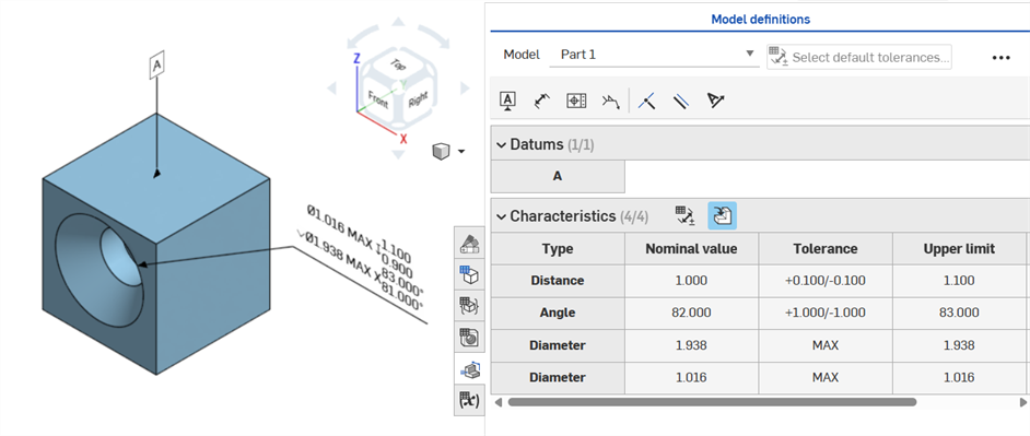
Les cotes des perçages sont visibles dans le tableau d'inspection une fois qu'un datum a été ajouté sur l'une des faces de la pièce.
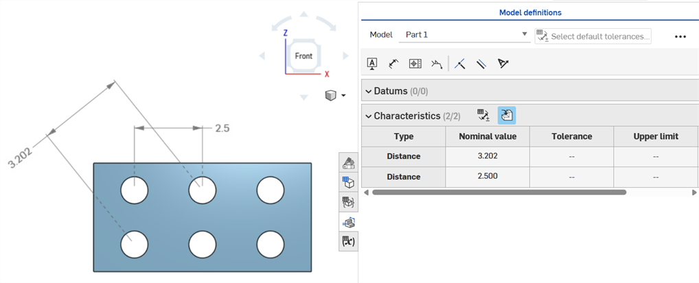
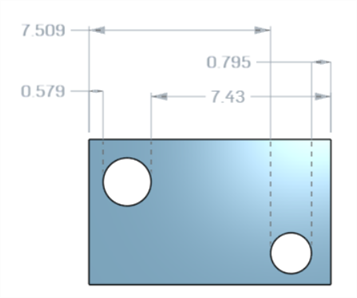
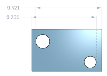
Cotes de distance des axes entre les cercles centraux à l'aide de l'outil Cote (![]() ) :
) :
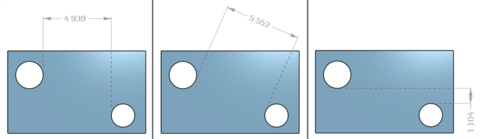
Cotes horizontales, diagonales et verticales minimales entre deux faces cylindriques à l'aide de l'outil Cote minimale (![]() ) :
) :
Cotes minimales entre les cylindres et les arêtes :
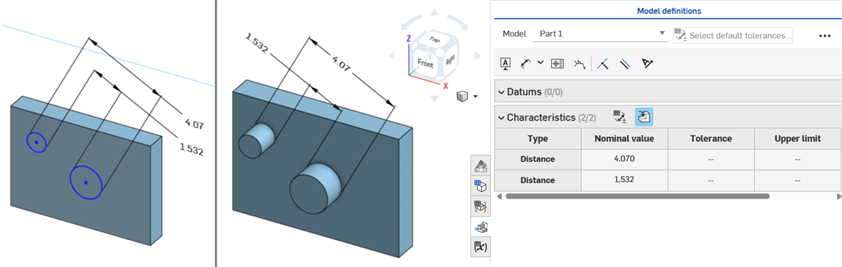
La cote diagonale minimale ajoutée dans une esquisse (à gauche) est affichée dans le tableau des caractéristiques une fois la pièce créée (à droite) :
Les cotes minimales horizontales et verticales ne peuvent pas être créées dans une esquisse pour le moment.
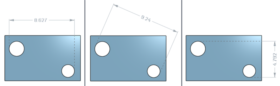
Cotes horizontales, diagonales et verticales maximales entre deux faces cylindriques à l'aide de l'outil Cote maximale (![]() ) :
) :
Cotes maximales entre les cylindres et les arêtes :
Cotes horizontales, diagonales et verticales maximales entre les faces de l'arc dans une rainure :
La cote diagonale maximale ajoutée dans une esquisse (à gauche) est affichée dans le tableau des caractéristiques une fois la pièce créée (à droite) :
Les cotes maximales horizontales et verticales ne peuvent pas être créées dans une esquisse pour le moment.
L'épaisseur est affichée dans le tableau d'inspection sous la forme d'une ligne Distance.
Extrusion fine (cote d'épaisseur 1) :
Révolution fine (cote d'épaisseur 1) :
Une distance à l'axe de symétrie d'une esquisse avec tolérance activée :
Si l'axe de symétrie est utilisé comme axe autour duquel pivote la géométrie d'esquisse, il est affiché sous forme de cote de Diamètre lorsque le tableau d'inspection est ouvert :
Au fur et à mesure que des annotations sont ajoutées, que des modifications de modèle sont apportées et que des mises à jour des fonctions sont appliquées, Onshape tente automatiquement de valider les données MBD associées.
Les validations se font pièce par pièce ; les annotations doivent donc faire référence à la géométrie de la même pièce ou de la même pièce composite.
Lorsqu'une caractéristique est invalidée, l'annotation et la caractéristique correspondante dans le tableau d'inspection sont rouges.
Les caractéristiques non valides peuvent être classées en deux catégories : références manquantes et valeurs non concordantes.
Une référence manquante se produit lorsque la géométrie utilisée pour définir une caractéristique n'existe plus ou a changé d'une manière qui rompt l'association. Cela peut être dû à la suppression d'une fonction, à un remplacement de face ou à une autre modification topologique.
Une non-concordance de valeurs se produit lorsque la valeur de la géométrie référencée ne correspond plus à la tolérance définie. Cela peut se produire, par exemple, lorsque le diamètre d'un perçage dépasse les limites spécifiées.
Corrigez les caractéristiques non valides en évaluant les causes potentielles.
Lorsque vous utilisez Comparer, sélectionnez les faces pour voir les annotations, les tolérances et les caractéristiques qui leur sont associées.
Validez et corrigez les erreurs en modifiant la liste des fonctions et les annotations MBD.
Les erreurs de MBD ne créent pas d'annotations ni d'entrées de ligne dans le tableau d'inspection, sauf si un ajustement du modèle invalide une entrée de ligne d'annotation existante.
Les erreurs sont affichées en rouge, comme les autres erreurs Onshape :
Erreur générée lors de l'extrusion depuis ou dans un solide. L'annotation ne génère aucune entrée de ligne dans le tableau d'inspection.
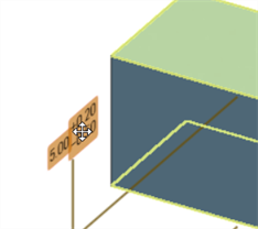
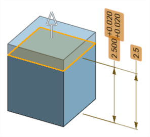
Si la géométrie est modifiée au point d'invalider une annotation spécifiée, l'annotation correspondante est en rouge dans la zone graphique et surlignée en rouge dans le tableau d'inspection pour signaler une erreur. Par exemple, la face supérieure de la boîte a été déplacée de 0,5 pouce, ce qui a créé une différence entre la valeur mesurée (3,5 pouces) et la valeur spécifiée (3 pouces) :
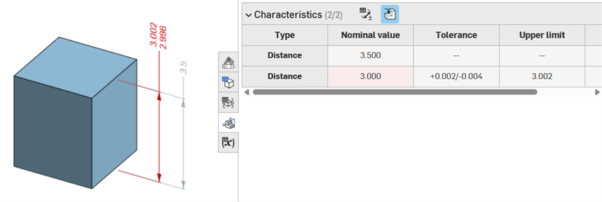
Exemples d'erreurs
-
Il manque une référence pour cette annotation. Cette erreur se produit lorsqu'une référence est manquante. Par exemple, la pièce A est extrudée jusqu'à la face de la pièce B, et une tolérance est ajoutée à la distance de décalage de l'extrusion de la pièce A.
-
Les deux faces doivent provenir de la même pièce. Les définitions des modèles ne sont valables que pièce par pièce. Par exemple, vous ne pouvez pas coter la distance entre une face de la pièce A et une face de la pièce B.
-
Les annotations MBD doivent toujours être associées à des faces. Les arêtes et les sommets ne peuvent pas être référencés pour le moment.
-
Les définitions des modèles ne sont valables que par pièce. Les pièces composites sont également couvertes. Par exemple, vous pouvez coter la distance entre deux faces de la pièce A ou deux faces de la pièce B, mais pas entre une face de la pièce A et une face de la pièce B. Pour ce faire, créez d'abord une pièce C composite à partir de la pièce A et de la pièce B. Vous pouvez ensuite coter la distance entre ces deux faces.
-
Passez la souris sur la ligne Type du tableau d'inspection pour mettre en surbrillance croisée la cote dans la zone graphique.
-
Lorsque vous modifiez la géométrie d'une pièce, toutes les définitions du modèle associées sont surlignées en orange :
-
Si une pièce ou un Part Studio est dérivé(e) via la fonction Dérivé, toutes les définitions du modèle sont en lecture seule et ne peuvent pas être modifiées. Vous pouvez toujours déplacer les annotations, et les cotes pilotées sont toujours mises à jour si la géométrie dérivée est modifiée. Cependant, les définitions du modèle sous-jacentes ne peuvent être ajustées que dans le Part Studio source, puis mises à jour dans la fonction Dérivé. Voir Dérivé pour plus d'informations.
-
Des commentaires peuvent être ajoutés pour identifier les cotes des esquisses, les cotes des fonctions, les légendes des perçages et les annotations des tableaux d'inspection (cotes, datums, tolérances géométriques) dans la zone graphique. Voir Ajouter des commentaires aux annotations MBD pour plus d'informations.