 Markieren
![]()
Sie können mit Skizzen-Profilelemente für Rahmen oder Bauteile markieren, um sie zu Blechformen hinzuzufügen oder daraus zu entfernen. Außerdem können Sie Geometrie auswählen, die Ausrichtung definieren und Eigenschaften hinzufügen.
Onshape bietet eine Bibliothek mit Standard-Strukturprofilen, die direkt in das Rahmen-Feature integriert sind. Es kann jedoch vorkommen, dass Sie eine benutzerdefinierte Bibliothek mit Rahmenprofilen erstellen müssen. Das Erstellen und Teilen benutzerdefinierter Profile, um sie mit dem Rahmen-Feature zu verwenden, ist äußerst einfach. In diesem Video wird das gezeigt, indem Sie eine Bibliothek mit Skizzen definieren, das Profil für verschiedene Größenoptionen konfigurieren und das Profil markieren, sodass die Schnittlisten-Tabelle mit den Segmenten und Segmenteigenschaften ausgefüllt wird.
Um eine neue Profilbibliothek zu erstellen, legen Sie zuerst ein neues Onshape-Dokument an. Sie können Profile in einem oder mehreren Bibliotheksdokumenten organisieren. Platzieren Sie das Bibliotheksdokument in einem Ordner im Stammverzeichnis der Company oder des Enterprise. Diese Vorgehensweise erleichtert das Teilen mit anderen Benutzern, die die Profile verwenden müssen.
Erstellen Sie eine Skizze des Profils in einem Part Studio, wobei Sie für jede Profilskizze ein eigenes Part Studio anlegen. Überlegen Sie sich beim Erstellen der Skizze, wie Sie das Profil ausrichten möchten. Fügen Sie ggf. Skizzenpunkte hinzu, die als zusätzliche Ausrichtungspunkte dienen. Definieren Sie die Skizze mit Bemaßungen und Beziehungen. Verwenden Sie Variablen, wenn Sie die Skizzenbemaßungen definieren, die Sie für verschiedene Profilgrößenoptionen konfigurieren möchten. Variablen erleichtern das Erkennen der wichtigen Werte des Profils. Benennen Sie das Part Studio und die Skizze um und wählen Sie einen aussagekräftigen Namen für das Profil. So können Benutzer leicht erkennen, wofür das Profil dient. Bei der Auswahl des Profils wird der Part-Studio-Name auf der obersten Ebene des Dialogfenster angezeigt, der Name der Skizze steht unten.
Wenn das Profil in mehreren verschiedenen Größen mit derselben Form vorhanden ist, konfigurieren Sie die Skizzenbemaßungen oder Variablenwerte. Erstellen Sie Konfigurationstabellen mithilfe von Konfigurations-Einträgen für jede Größe. Konfigurieren Sie dann die Bemaßungen oder Variablen (falls verwendet). Bearbeiten Sie die Skizze, rechtsklicken Sie auf jede Bemaßung, um die Konfiguration zu steuern, und wählen Sie „Bemaßung konfigurieren“ aus. Wenn Sie die Skizze mit Variablen definieren, bearbeiten Sie die Variable, rechtsklicken dann auf den Wert und wählen Sie „Konfigurieren“ aus. Bearbeiten Sie die Werte in der Konfigurationstabelle.
Starten Sie als Nächstes ein neues Markieren-Feature und wählen Sie in der Dropdown-Liste den Eintrag „Rahmen“ aus. Das Markieren-Feature fügt dem Profil Eigenschaften hinzu. Beim Verwenden eines Rahmen-Features zeigt die Schnittlisten-Tabelle Spaltenüberschriften wie „Standard“ oder „Beschreibung“ an und Werte für diese Eigenschaften werden automatisch ausgefüllt.
Wählen Sie das Skizzenprofil im Grafikbereich oder in der Features-Liste aus. Wenn zusätzliche Ausrichtungspunkte erforderlich sind, erweitern Sie das Auswahlfeld und wählen die Punkte in der Skizze aus, die als Ausrichtungspunkte dienen sollen. Geben Sie dann Zahlen bzw. Text in den Feldern „Standard“ und „Beschreibung“ ein. Werden diese Felder leer gelassen, wird diese Spalte beim Verwenden des Profils nicht zur Schnittliste hinzugefügt bzw. diese Zelle wird als „Nicht eingerichtet“ angezeigt, wenn für andere in der Struktur verwendete Profile diese Spaltenüberschrift definiert ist. Sowohl Standard- als auch Beschreibungseinträge können konfiguriert werden. Rechtsklicken Sie auf das Feld im Dialogfenster „Profil markieren“ und wählen Sie „Konfigurieren“ aus. Bearbeiten Sie dann die Zellen in der Konfigurationstabelle.
Wenn Sie weitere Eigenschaften für das Profil angeben möchten, klicken Sie auf „Spalte hinzufügen“ und geben Sie die Kopfzeilen- und Wertinformationen ein. Auf die gleiche Weise können Sie der Schnittlisten-Tabelle weitere Spalten hinzufügen. Klicken Sie auf das Häkchen, wenn Sie fertig sind. Diese Eigenschaften können nicht konfiguriert werden. Klicken Sie im Dialogfenster auf die Löschen-Schaltfläche (X), um alle Spalten zu entfernen.
Klicken Sie auf das Häkchen, um das Markieren-Feature zu akzeptieren. Dieses Profil kann jetzt mit den in diesem Dokument enthaltenen Strukturen verwendet werden. Beginnen Sie ein neues Rahmen-Feature in einem anderen Part Studio und klicken Sie im Dialogfenster auf die Skizzenprofil-Auswahl. Wählen Sie im aktuellen Dokument das Profil aus. Passen Sie die Konfiguration an und klicken Sie auf „Erzeugen“, um die konfigurierten Werte anzuwenden. Wählen Sie dann das Skizzenprofil aus.
Bewahren Sie beim Erstellen benutzerdefinierter Profilbibliotheken die Profile in einem anderen Dokument auf als die Designs, in denen sie verwendet werden. In diesem Fall versionieren Sie das Dokument, das die Profile enthält, sobald es fertig ist. Ab diesem Zeitpunkt kann das Profil mithilfe verknüpfter Dokumente referenziert werden. In diesem Beispiel enthält ein anderes Dokument die benutzerdefinierten Profile. Klicken Sie auf „Andere Dokumente“, navigieren Sie zu dem Dokument und wählen Sie das Skizzenprofil aus.
Um anderen Benutzern den Zugriff auf benutzerdefinierte Profile zu ermöglichen, muss das Dokument oder der Ordner, der die Profile enthält, geteilt werden. Benutzer, die in dem Rahmen-Feature auf die benutzerdefinierten Profile verweisen müssen, benötigen nur Berechtigungen zum Anzeigen oder Verknüpfen. Benutzer, die beim Organisieren der benutzerdefinierten Profile helfen sollen, benötigen Berechtigungen zum Bearbeiten und Verknüpfen. Teams zum Teilen zu verwenden ist praktisch, weil Sie so sicherstellen können, dass die richtigen Personen Zugriff haben. Auch erleichtert es den Zugriff für organisatorische Zwecke. Bei personellen Veränderungen im Unternehmen ist es einfacher, das Hinzufügen oder Entfernen von Benutzern als Team zu verwalten als jeden Benutzer einzeln.
Zum Markieren eines Profils, das Sie erstellt oder geändert haben, verwenden Sie die Informationen in der Schnittlisten-Tabelle als zusätzliche Spalten:
- Click the Tag icon (
 ) to open the Tag dialog:
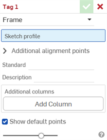
-
Wählen Sie den zu markierenden Rahmen aus.
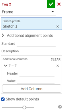
- Wählen Sie im Feld Skizzenprofil die Skizze in der Feature-Liste aus, die als Skizze für das Profil dient.
-
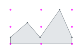
Standardmäßig ist die Option Standardpunkte anzeigen im Dialogfenster aktiviert. Dadurch wird das Skizzenprofil mit einem magentafarbenen 9-Punkt-Ausrichtungsraster überlagert. Deaktivieren Sie diese Option, um die Ausrichtungspunkte auszublenden.
-
Wählen Sie im Feld Zusätzliche Ausrichtungspunkte alle anderen Punkte in Ihrer Skizze aus, die Sie für die Ausrichtung verwenden möchten.
- Geben Sie in das Feld Standard den Wert ein, der in der Standard-Spalte der Schnittlisten-Tabelle angezeigt werden soll.
- Geben Sie in das Feld Beschreibung eine Beschreibung ein, die in der Beschreibung-Spalte der Schnittlisten-Tabelle angezeigt werden soll.
- Wenn Sie weitere Spalten mit Informationen für das Profil erstellen möchten, klicken Sie auf Spalte hinzufügen:
-
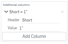
Geben Sie in das Kopfzeilen-Feld den Namen der neuen Spaltenkopfzeile ein, die in der Schnittlisten-Tabelle des Zusatzprofils erscheinen soll, sowie den Wert:
-
Klicken Sie auf Spalte hinzufügen, um der Schnittlisten-Tabelle ein weiteres Spalten-Wert-Paar hinzuzufügen.
-
Klicken Sie auf das Häkchen (
 ).
).
Die beste Vorgehensweise ist, ein Profil zu markieren, eine Version zu erstellen und diese Version des Profils im Rahmen zu referenzieren.
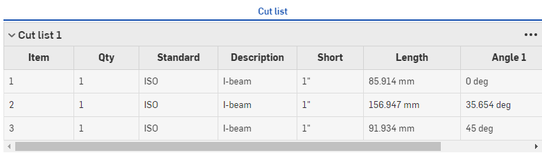
Beachten Sie die neuen Werte in der Spalte „Beschreibung“ und die zusätzliche Spalte „Kurz“ mit den entsprechenden Werten (siehe oben).
Die neuen Informationen für das Profil werden in der Schnittlisten-Tabelle angezeigt, nachdem sie in einem Rahmen-Feature verwendet wurden, gefolgt von einem Schnittlisten-Tabellen-Feature zur Erstellung der Tabelle. Klicken Sie auf ![]() rechts im Fenster, um die Tabellen-Palette zu öffnen.
rechts im Fenster, um die Tabellen-Palette zu öffnen.
Form-Markierungen kennzeichnen Bauteile, die nicht aus Blech gefertigt sind und als Form-Features zum Hinzufügen oder Entfernen von Material zum Blechmodell verwendet werden.
So markieren Sie Bauteile:
- Klicken Sie auf das Markieren-Symbol (), um das Dialogfenster „Markieren“ zu öffnen.
-
Wählen Sie zu markierende Form aus:
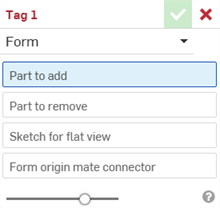
- Wählen Sie für das Feld Hinzufügendes Bauteil das Bauteil in der Bauteil-Liste oder im Grafikbereich aus, das Sie zum Blech hinzufügen möchten.
- Wählen Sie für das Feld Zu entfernendes Bauteil das Bauteil in der Bauteil-Liste oder im Grafikbereich aus, das Sie vom Blech subtrahieren möchten.
- Wählen Sie als Skizze für flache Ansicht die Skizze aus, die für die flache Ansicht des Blechmodells verwendet werden soll.
- Wählen Sie die Formursprungs-Verknüpfungsverbindung aus. Diese bestimmt die Richtung, in der die Form das Blechmodell verändern soll. Gehen Sie mit der Maus über das Modell im Grafikbereich, um eine implizite oder explizite Verknüpfungsverbindung auszuwählen. Wenn keine ausgewählt ist, erstellt das Feature eine am Ursprung des Part Studios.
- Klicken Sie auf das Häkchen ().
Wählen Sie kein Blechbauteil aus. Wählen Sie ein geometrisches Standardbauteil aus.
Wählen Sie kein Blechbauteil aus. Wählen Sie ein geometrisches Standardbauteil aus.
Sie können nur ein (1) gültiges Form-Markieren-Feature pro Part Studio haben. Erstellen Sie eine einzige Form pro Part Studio.
-
 Rahmen: Erstellen Sie eine Sammlung ausgetragener Körper, die ein gemeinsames Profil haben und durchgängig angeordnet sind.
 -
 Rahmen trimmen: Trimmen Sie Segmente als geordnete Gruppen.
 -
 Knotenblech: Erstellen Sie Knotenbleche zwischen benachbarten Rahmensegmenten.
 -
 Endkappe: zum Erstellen einer oder mehrerer Endkappen für Rahmensegmente.
 -
 Schnittliste: Erstellen Sie eine Schnittliste aller Segmente eines Rahmens mit ihren Merkmalen. Dadurch entsteht auch ein zusammengesetztes Bauteil für die Sammlung.
 -
Tag: Sie können mit Skizzen-Profilelemente für Rahmen oder Bauteile mit Tags markieren, um sie zu Blechformen hinzuzufügen oder daraus zu subtrahieren. Außerdem können Sie Geometrie auswählen, die Ausrichtung definieren und Eigenschaften hinzufügen.