 Weld Symbol
![]()
Place weld symbols on a drawing. Weld standards default to the standard specified for the drawing. To change the weld standard, access the drawing’s
Properties panel (![]() )
located on the right side of the page.
)
located on the right side of the page.
Steps
- Click
 .
.
The drawing's standard (ISO or ANSI) determines which version of the dialog is displayed.
- In the dialog, describe the weld symbol using the fields.
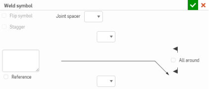
- Select either Joint spacer (with accompanying defaults) or a joint type (and specify options).
- Joint spacer types:
- Double V groove
- Double bevel groove
- Double U groove
- Double J groove
- Double flare V
- Double flare bevel
- Joint types:
- Square groove
- V groove
- U groove
- J groove
- Bevel groove
- Single bevel butt broad root
- V flare groove
- Bevel flare groove
- Bead joint
- Fillet joint
- Plug or Slot joint
- Seam joint
- Spot joint
- Seam centered joint
- Spot centered joint
- Joint spacer types:
- Click in the drawing to place the weld symbol and weld descriptions, on a line or vertex.
- Check Stagger to indicate staggered welds (available for all ANSI and ISO joints, when the Symmetric option is selected or when the top and bottom joints are the same).
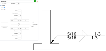
- Check Symmetric to indicate symmetric welds. This option is available for all ANSI and ISO joint types but not for ANSI joint spacers.
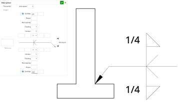
- Optionally, select a Second fillet to indicate a fillet with a left vertical line in the symbol. This option is available for certain ANSI and ISO joints.
- Check Reference to activate the text box and enter notes.
- Check ‘All around’ to indicate the weld should surround the entire joint.
- Select a ‘flag’ to indicate an action to be performed in the field.
- Click in drawing to place weld symbol.
To add another leader, right-click the leader and select "Add leader". Click to place additional leader. Repeat to add more leaders.
-
Click
 when finished (or
 to cancel).
There is no need to click directly on the point once it is visible. While moving the mouse to place the weld symbol, you'll notice thin, dashed lines as the cursor passes near other entities. These are inferencing lines tat you are able to align the weld symbol to; simply click when you see the line appear to align the weld symbol to that line.
Add/remove leader nodes
- Right click on the leader and click Add node:
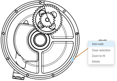
A node will appear on the leader. To add another node, right click on the leader and select Add node again.
- To remove a node from a leader, right click on the node and select Remove node.
- You are also able to add leaders to nodes by right clicking on the node and selecting Add leader. This will add a leader starting from that node and ending wherever you click next.
Styling a weld symbol
To style a weld symbol:
-
Click on the weld symbol you want to style, then click the Styles panel icon on the right side of the page:
-
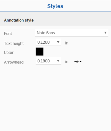
This opens the Styles panel, where you can edit the font, text height, color, and arrowhead of the weld symbol:
![]()
Tip
- You can group welds with callouts. See Callout (Balloon) for more information.