Modal Simulation 
![]()
Only available for
Modal analysis, or more specifically, natural frequency analysis is used to provide information on the stiffness or mechanical resonance of an assembly structure. It is used by designers and engineers who require vibrational analysis within Onshape and is commonly used in industrial equipment, automotive, and aerospace industries, among others. Modal analysis is often required for subsequent dynamic analysis; for example, modal frequency response and modal transient analysis are used in safety calculations.
In general, Modal analysis is a broad area of study. More specifically, Onshape Modal simulation focuses on what is referred to as normal modes, eigenvalue analysis, or natural frequency analysis. It is a technique in structural dynamics used to characterize how a structure tends to dynamically deform and vibrate, without needing to model the external forces that would be applied to the structure. The natural frequencies of a structure are dependent only on the structure's shape (geometry), part-to-part connections (boundary conditions), and material composition, such as mass and stiffness.
For engineers and designers, understanding the vibrational characteristics of an assembly is critical because being exposed to vibration (cyclic loading) may result in structural damage such as cracks, resonance, or even catastrophic failure. Natural frequency analysis is often the first step in further vibration or fatigue analysis. Many companies also test their products' response to vibrational excitations with shaker tables, impact hammers, and other physical test setups.
Designers can interactively increase or decrease an assembly's stiffness with changes to the shape, materials, or mate connections. It is important to calculate and ensure the natural frequencies of vibration are far greater than (or far removed from) any possible excitation frequency that your system is likely to encounter.
Once an Assembly is created with material properties, it can be analyzed. Visualizations show the energy needed for deformation per mode. Onshape automatically infers connectivity between Assembly Mates, intuitively supports Assembly Configurations, and keeps pace with real-time Part Studio edits.
Consider the efficiency of using natural frequency analysis along with configurations or global variables to experiment with a design until it is within your desired specifications.
This workflow assumes you have a completed CAD model in an Assembly tab.
-
Before creating a simulation, the following two criteria must be met:
-
All instances in the assembly must have a material assigned.
-
At least one instance must be unfixed.
-
-
Click the Simulation panel icon (
 ) to open the Simulation panel:
-
At the top of the panel click the Add simulation dropdown and select Add modal simulation.
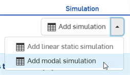
-
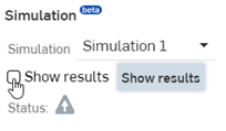
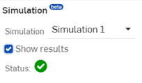
Check Show results in the Simulation area of the Assembly list. As the results are calculated, a blue progress bar indicates the time remaining before the final calculation is displayed. Early iterations are displayed in the stress scale. When finished, the blue progress bar reads complete, and then a checkmark is placed next to the Status signifying the calculation (convergence) is complete:
-
The simulation results and color scale are listed at the top. If no rigid body modes are present, then Mode 1 is selected by default. Use the results dropdown to select other result modes.
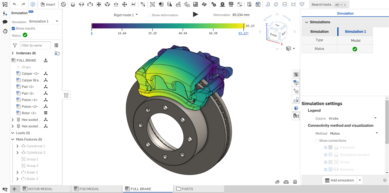
Example of a Modal simulation performed on a car brake
This dropdown is located at the bottom of the panel if you have other Simulations in your Assembly.
Overridden mass values are ignored in simulation results. If a mass override exists, a warning tooltip is displayed both before and after the Show results checkbox is enabled. Hover over the Status icon to see the warning:
When results are loaded for a simulation, the color scale and results appear at the top of the graphics area. These are outlined below:

-
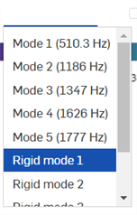
Results - Results are broken out into two sections: 1-15 non-rigid Modes and many possible Rigid modes. Only one mode is displayed at a time, but you can switch between any mode. View the relative amplitude of oscillations when switching between modes.
-
Mode 1-15 (x Hz) - Listed in order of ascending frequency, each Mode corresponds to the unique deformation pattern (or mode shape) through which the structure oscillates. The rate at which that oscillation occurs is listed in Hertz (Hz) to the right of the mode count.
When selected, an Energy field appears above the Deformation field:

All three fields (Frequency, Energy, and Deformation) control the amplitude of the mode shape displaced, and they are all linked to each other. The Displacement corresponds to the maximum deformation present throughout the model. The Energy quantifies the amount of work that must be added to the structure in order for it to oscillate in the prescribed pattern, frequency, and amplitude.
If Displacement is set by the user, then Energy is re-calculated for each different non-rigid Mode. If Energy is set by the user, then Displacement is re-calculated for each different non-rigid Mode, and the animation amplitude adjusts accordingly.
You can adjust the Energy or Deformation scale factor (amplitude) up or down, and the Frequency remains constant. You can also change the units used for Energy in your user preferences or the document's Workspace units.
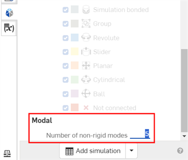
By default, 5 non-rigid Modes are displayed. However, you can select up to 15 by entering a value in the Number of non-rigid modes field at the bottom of the Simulation panel:
-
Rigid modes - A path of motion in which the structure(s) may move without deformation or a change in shape, similar to how one could manually manipulate the translation/rotation of each instance in the Assembly.
The number of Rigid Modes matches whatever open degrees of freedom happen to be present in the Assembly. This could be none or many.
-
-
Show deformation - Enable this checkbox to display the deformation on the Assembly Instance(s). This is the unique pattern of how a structure moves during a specific vibration.
-
Animation icon - This icon
 animates the simulation. The animation loops as long as the animation is enabled. As it is animated, the starting position is shown as an outline of the instances, and the Assembly moves at a constant pace. The icon is a toggle. Once run, the icon switches to a stop button icon
 . Pressing this icon stops the animation.
-
Color Scale - The color scale represents the deformation (amplitude) from lowest to highest values. This deformation scale is tied to a physical quantity, the energy required in order to deform the structure through that mode shape, frequency, and amplitude. This takes into account the strength and stiffness of the assembly when visualizing the deformations, offering more guidance on the vibrational characteristics.
Click the lower or upper scale link to numerically enter the minimum and maximum scale values, respectively. Click the Reset icon to the right of these numbers to reset the minimum or maximum to the default value. Drag the minimum and maximum vertical scale lines to increase the minimum or decrease the maximum scale limits.
It is not required to check the Show deformation checkbox to view deformations during simulation animation.
-
Onshape Modal Analysis supports free and constrained boundary conditions but not loads. The application of external loads is referred to as pre-stressing or stress stiffening. While Modal simulation is active, loads are automatically suppressed and may not be added to the Assembly.
-
Because loads cannot be applied while Modal simulation is active, there is only one condition that can define the modal analysis: the state of the Assembly. Therefore, only one Modal simulation may be added to the Assembly.
-
Onshape’s Modal Analysis uses linear dynamics, which assumes a linear behavior of materials, so it is inappropriate for non-linear materials such as rubber and does not include damping effects.
-
Onshape’s Modal analysis may experience longer run times with thin-walled solids.
-
There are two types of Simulation available:
-
Linear static. See Simulation for more information on Linear static simulation.
-
Modal
-
-
Different from static analysis, dynamic analysis loads are applied as a function of time or frequency. This induces time or frequency-varying responses (displacements, velocities, accelerations, forces, and stresses). Onshape does not yet support dynamic loads. As a result, Modal simulation only calculates natural frequencies.
-
Overridden mass values are ignored in simulation results.
-
Typically, for most engineering applications, Engineers are concerned with the first few (lowest) natural frequencies and their corresponding mode shapes, as these are most likely to be excited under normal operating conditions. For simpler structures, this is usually the first 3 to 5 modes, the modes found in the Results dropdown list. If required, Onshape's Modal simulation provides up to 15 non-rigid Mode results.
-
There is no limit to the number of natural frequencies that one can identify. However, with each increasing natural frequency, the energy required to deform the structure(s) into that shape grows higher and higher. For more complex structures, or with more advanced analysis that studies a broader range of excitations, Engineers might be interested in dozens or even hundreds of modes.
-
The number of non-rigid modes for an Assembly increases dramatically as the number of unconstrained (or free-floating) Instances in an Assembly increases. For an Assembly with many independent, unconstrained bodies, users should expect the response time for a Modal simulation to increase considerably.
-
Symmetric Parts/Assemblies result in symmetric (duplicate) non-rigid Modes. For such structures, expect to see some non-rigid modes with mirrored or rotationally symmetric deformation profiles with (nearly) exactly the same natural frequency. These could potentially be combined into the same Mode during your analysis of the simulation results.