Simulation

![]()
Only available for
Simulation is used to evaluate the stresses and displacements between externally-loaded instances in an Assembly, allowing you to examine how an assembly reflects the loads, materials, and boundary conditions found in real-world use.
Simulation currently supports structural linear static finite element analysis, outlined below, and Modal analysis, or more specifically, natural frequency analysis, outlined in the Modal simulation topic. Simulation does not support fluid or thermal analysis.
Each simulation becomes part of your Assembly, as do the structural loads which characterize it. These loads may be reconfigured across multiple simulations, and each simulation may be reapplied across multiple assembly configurations. Interactions between instances are inferred from Mates, eliminating needless re-authoring of the model. Simulation results always reflect the current state of your model.
Product designers and engineers can use Simulation to test models early in the design and prototyping process. Interactively change materials, loads, constraints, or results, and compare multiple simulations, viewing these results immediately. This reduces the need for costly prototype iterations and optimizes your models to better meet specific design criteria.
Simulation is used to evaluate the stresses and displacements between externally-loaded instances in an Assembly, allowing you to examine how an assembly reflects the loads, materials, and boundary conditions found in real-world use. Ensure you have a completed assembly first.
Before creating the simulation, two conditions need to be met. First, at least one instance must be fixed in the Assembly. Right-click on the Axle and select Fix from the context menu. Second, All instances except the one that is fixed require a material assigned to them. This can be done in the Part Studio for each part, or in the Assembly BOM table. Open the table and double-click on the Material field for the associated instance row (in this example, the Caliper bracket), and select a material from the Material dialog.
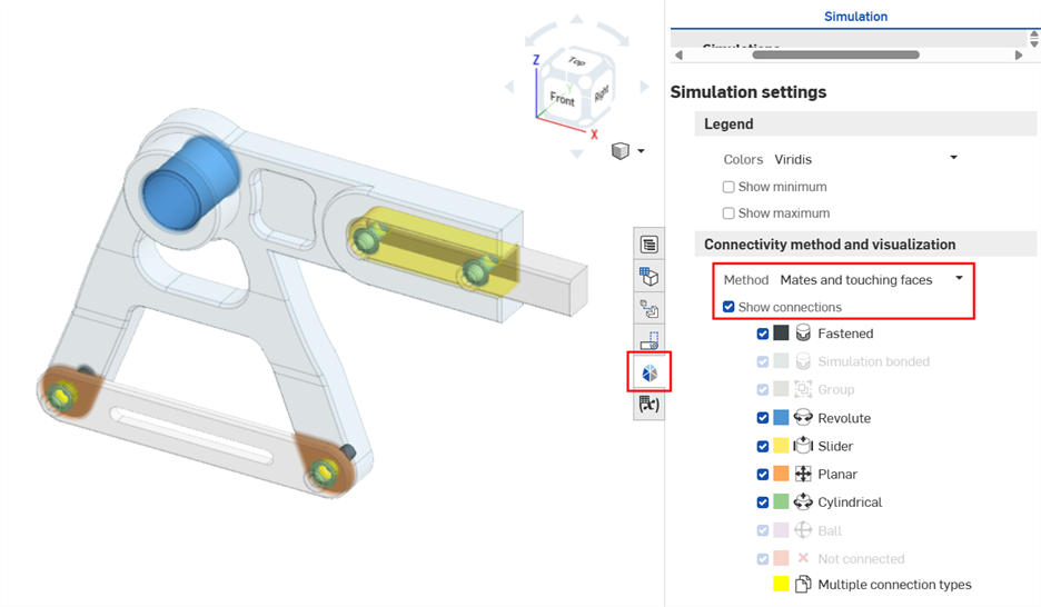
Visualize the Mate connections in the assembly. Open the Simulation panel and check Show connections. If desired, select an alternate Method to determine how instances in the assembly are connected (bonded together). Connectivity method and visualization can be changed at any point before, during, and after the simulation.
Click one of the five Simulation tools on the Assembly toolbar: Force, Moment, Bearing, Pressure, or Acceleration. Here, Force is selected. The Force dialog opens. Note that you can switch between simulation types using the dropdown at the top of the dialog.
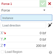
Next, select an Instance, the Forcing bracket here. Select a Load direction using an implicit or explicit Mate connector or instance edge. Enter the Magnitude for the load along any of the three axes (X, Y, and/or Z). These are the forces borne on the fixed instance. For this example, a load of 50 N is applied to the Z axis.
By default, the load is applied to the whole body. If desired, optionally check Load region, and select Faces to load, to narrow the load to a specific region. Click the checkmark to close the Load dialog.
Check Show results. As the results are calculated, a blue progress bar indicates the time remaining before the final calculation displays. Early iterations are displayed in the stress scale. When finished, the blue progress bar reads complete, and the checkmark is placed next to the Status.
Click the dropdown on the simulation toolbar to select from 5 different result metrics. Hover your mouse over the instance in the graphics area to display a numerical readout next to the cursor. This indicates the stress or displacement amount of the instance located under the cursor. To animate the simulation, click the Play toggle above the color scale. To stop playback press the Stop toggle. Check Show deformation to display the deformation overlaid with a view of the original assembly as a wire frame.
Simulations are located at the top of the Assembly list on the left side of the screen, just above the Instances list. Any simulation loads are automatically added into a Loads dropdown in the Instance tree, between the Assembly instances and the Mate features. Both are outlined in the image below:
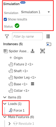
-
Simulation - Title of the Simulation area in the Assembly list.
-
Simulation - The editable label for the current simulation. Enter the name for the current simulation here.
-
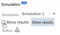
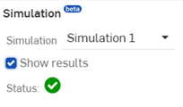
Show Results - When checked, this begins showing the results of the simulation. As the results are calculated, a blue progress bar indicates the time remaining before the final calculation is displayed. Early iterations are displayed in the stress scale. A green checkmark next to the Status indicates the calculation (convergence) is complete.
-
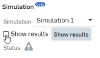
Status - Indicates the current status of the simulation. If the simulation is in an error state, a yellow warning icon is visible to the right of the Status label. Hovering over the icon provides a tooltip to indicate the error and offers a suggestion on how to fix the error. If the simulation is ready to proceed, a gray information icon is visible indicating the show results can be checked to start the simulation:

Status with warning indicator explaining that a fixed instance is required before a simulation takes place.

Status with an information indicator explaining the Show results are required before the simulation is run.
Overridden mass values are ignored in simulation results. If a mass override exists, a warning tooltip is displayed both before and after the Show results checkbox is enabled. Hover over the Status icon to see the warning:

A simulation cannot be performed until at least one Load is assigned to the Assembly. They are assigned on an instance-by-instance basis, with no limit to the number or type that may be assigned to any instance, with the exception of a fixed part/instance, which, in reference to the simulation, is immutable. A Load cannot affect any change to or through a fixed part/instance.
Simulation load tools are found at the top of the screen at the far right in the Assembly toolbar. There are six Load tools: Force, Moment, Bearing, Pressure, Acceleration, and Angular velocity. Each are outlined below:

Force

Simulates the effect of an evenly distributed, linear force on an instance. By default, the force is distributed throughout the instance’s volume. If instead a Load region is enabled, and specific faces of the instance selected, the force is distributed evenly over the faces.
Moment

Simulates the effect of an evenly distributed Moment (torque) on an instance. By default, this moment is distributed throughout the instance’s volume. If instead a Load region is enabled, and specific faces of the instance selected, the moment is evenly distributed over the faces.
Bearing

Simulates the effect of a bearing load on the faces of an instance. This Bearing load produces the total equivalent load as a force, but it is only applied to an instance's faces, and its distribution is not uniform (unless all faces are coplanar). Instead of an even distribution, Bearing distributes its load proportionate to the degree to which it is aligned normal to, and facing toward, the loaded faces. If the bearing load has no positive projection onto the loaded faces, it contributes no load to the simulation.
Pressure

Simulates the effect of an evenly distributed Pressure on the faces of an instance. Similar to a Bearing load, Pressure is only applied to an instance's faces. Pressure magnitude is only positive, but by toggling the Load direction arrow, it either pushes into a face (default) or pulls away from a face (suction).
To apply a pressure load:
-
In the Instance field, select an Assembly instance.
-
Select all faces to which you want the pressure applied (Faces to load). This applies the pressure to the selected faces of the instance.
Acceleration

Simulates the effect of a static, uniform, linear acceleration acting on an instance. Acceleration is only applied to the whole instance; individual faces cannot be loaded. The result of an Acceleration load on an instance is precisely equivalent to that of a proportional force applied to the same instance, in the same direction, if the mass of the instance is taken into account.
Angular velocity

Simulates the effect of an object's angular velocity by applying the corresponding centrifugal load throughout an instance during a linear static analysis.
The Angular velocity load tool does not simulate actual rotation; it simulates the inertial loads that would be present if the instance were rotating in the prescribed manner. Be sure to model the assembly appropriately so the loaded instance can exist within an accelerating frame of reference. (This should not require the use of Inertial relief, maintaining that the instance is properly assembled and loaded exclusively using Angular velocity.)
Any instances meant to rotate along with the loaded instance must be individually and separately loaded.
Load tools dialog
Once a simulation load tool is selected, the load dialog opens. This is a common dialog shared by all six tools:
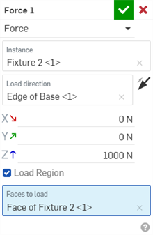
-
Force (load) 1 - Editable load label, which is used under the Loads dropdown in the Assembly Instance list and the Simulation panel.
-
Force (load) dropdown - The load dialog is common to all six tools. Use this dropdown to switch between tools for the current load; for example, from Force to Moment:
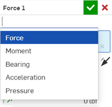
-
Instance - The instance in the assembly on which the load is applied. Only one instance can be selected in this field. Multiple instances are not supported.
-
Faces to load (Bearing and Pressure loads only) - With Bearing and Pressure loads, the loads must be applied directly to the instance faces. Any number of faces may be selected, but they must all belong to the Instance identified in the Instance field.
-
Load direction - With this field highlighted, select an existing Mate connector or click on a location to create a new Mate connector that drives the load direction. By default, Loads are aligned with the Mate connector’s Z-Axis; click the reverse arrow icon
 to reverse the direction of the load. A Pressure load does not require a Mate connector to define its direction. Use the reverse arrow icon to switch between pushing into and pulling away from the face. Load direction is configurable on a simulation-by-simulation basis.
-
X/Y/Z Magnitude - The numerical value of the load being borne by the instance. Pressure requires only a single Magnitude entry. When applying a Load direction in the Load dialog, the Mate connector's X, Y, and Z axes are used as the coordinate system to drive the corresponding load direction's X, Y, and Z axes and related directional loads. Magnitudes are configurable on a simulation-by-simulation basis.
-
Load region - By default, the load is borne by the instance. If instead you wish to localize the applied load to only part of the instance, check the Load region box. Then, select one or more faces of the instance bearing the load. Bearing and Pressure do not have a Load region checkbox, but do require you to select Faces to load. Acceleration does not have a Load region option.
A Mate connector created here cannot be referenced anywhere else in the Assembly.
Onshape automatically suppresses new loads for non-active simulations.
Load direction arrow and context menu
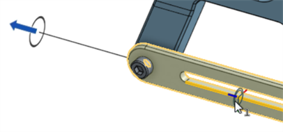
When an Instance and Load direction is selected in the Load dialog, a solid line extends from the instance outward, and a load direction arrow is placed at the end of the line. Each load has a unique icon associated with it. If selected from the graphics area, the icon and loaded instance region turns orange.
Right-clicking on the load direction arrow opens the following context menu:
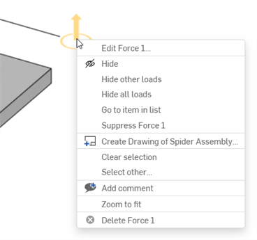
The commands related to simulation are:
-
Edit Force (load) 1 - Opens the selected load dialog.
-
Delete Force (load) 1 - Deletes the selected load from the Assembly.
For information on the other items found in this context menu, see Context menus.
When results are loaded for a simulation, the color scale and results appear at the top of the graphics area. The six tick marks along the bottom of the color band indicate the magnitude of the stress at each different hue:

The lower (minimum) value and upper (maximum) value tick marks can be adjusted by the user. Click the value and a field opens to enter the new value. An asterisk (*) is used to indicate that the original value was edited. Click the Reset button (![]() ) to return to the original value:
) to return to the original value:

Max stress value lowered (left image), reset (middle image), which resets the legend to the original max value (right image).
Result options
You can select from 5 different result options:

-
von Mises stress - A scalar value of stress that can be computed and is used to predict yielding of materials under complex loading from the results of uniaxial tensile tests. The von Mises stress satisfies the property where two stress states with equal distortion energy have an equal von Mises stress. It is a measure of energy density, as opposed to principal stress, which is a real stress.
The set minimum value tick mark must be lower than the set maximum value tick mark, and the set maximum value tick mark must be higher than the set minimum value tick mark.
The minimum value always defaults to 0, even if the lowest stress value present in the results is greater than 0.
To the right of the maximum value tick mark and color bar, a number appears to indicate the highest stress value present within the results. Often, this value sits near a computational singularity and is not a useful value.

Onshape performs a statistical analysis and sets a useful maximum value that is less than this highest-most value. This is used for the upper bound of the color bar’s range. The statistical analysis is conducted as follows:
-
For each part in the Assembly, Onshape creates a uniform point sample over each surface of the part.
-
These points are arranged in order of ascending stress. The point value that marks the 95th percentile is considered the “useful legend maximum” for that part.
-
After each “useful legend maximum” is found for all assembly parts, those values are arranged in ascending order. The highest value of all becomes the default value for the maximum value tick mark.
By default, the stress is set in MPa, unless your units are set to a different measurement (under Account > Preferences > Units).
-
-
Signed von Mises stress - Similar to the von Mises Stress, except that the minimum stress tick mark is not preset to 0. Instead, the same statistical analysis outlined above is performed here for both sides of the Signed von Mises stress legend. As a result, the values to the far left and far right of the color bar indicate the lowest and highest values found in the simulation results, while the left-most tick mark and the right-most tick mark represent the statistically significant lower and upper bound for the legend.
By default, the stress is set in MPa, unless your units are set to a different measurement (under Account > Preferences > Units).
-
Safety factor - Yield strength divided by the von Mises stress. This allows you to view how the stress levels for any given instance relate to the Tensile yield strength of that instance. It helps to point out problematic and non-problematic areas of stress in the simulation.
By default, Safety factor always presents the same legend, regardless of the simulation results. Unlike any of the other results types, values decrease from left to right, since higher safety factors (on the left) are associated with lower stress and strain (like all the other result types). The minimum value tick mark is set to 3.5, and the maximum value tick mark is set to 1.0. This is a standard design range for those seeking highly performant parts. The value to the far left of the color bar is set to 1,000 and the value to the far right of the color bar is set to 0.
-
Max principal stress - Maximum principal stress is the maximum normal stress acting inside the component and its position.
The legend and presentation of results for Max principal stress behave in the exact same manner as von Mises stress.
By default, the stress is set in MPa, unless your units are set to a different measurement (under Account > Preferences > Units).
-
Displacement - Displays the simulation result as a measurement of displacement.
By default, Displacement results do not show values to the far left and far right of the color scale. The minimum value tick mark is always set to 0 by default, and the maximum value tick mark is always set to the highest displacement value present in the simulation results. If the user chooses to edit either of these legend bounds, then a far left or far right value appears, equal to the original left/right values.
By default, the displacement is set in mm, unless your units are set to a different measurement (under Account > Preferences > Units).
Additional color scale options
-
Show deformation - Enable this checkbox to display the deformation (stress/displacement) of the load. Setting the scale lower shows less deformation. Setting the scale higher shows more deformation.
-
Animation icon - This icon
 animates the simulation. The animation loops as long as the animation is enabled. As it is animated, the starting position is shown as an outline of the instances, and the Assembly moves based on the applied load. The icon is a toggle. Once run, the icon switches to a stop button icon
 . Pressing this icon stops the animation.
-
Deformation scale - Allows you to set the scale lower or higher, to visually display more or less deformation. When Show deformation is enabled (checked) and/or the simulation is animated, this scale is applied to the deformation. The Deformation scale is based on the maximum deformation across the assembly; the default is set such that the deformation is 15% of the overall bounding box diagonal — the overall movement is always the same across any scale assembly.
-
Color scale - The color scale represents the load measurements from lowest to highest. Click the lower or upper scale link to numerically enter the minimum and maximum scale values, respectively. Click the Reset icon to the right of these numbers to reset the minimum or maximum to the default value. Drag the minimum and maximum vertical scale lines to increase the minimum or decrease the maximum scale limits.
It is not required to check the Show deformation checkbox to view deformations during simulation animation.
The Simulation panel is accessed at the far right of the window, and contains the Simulation table at the top, and Simulation settings at the bottom.

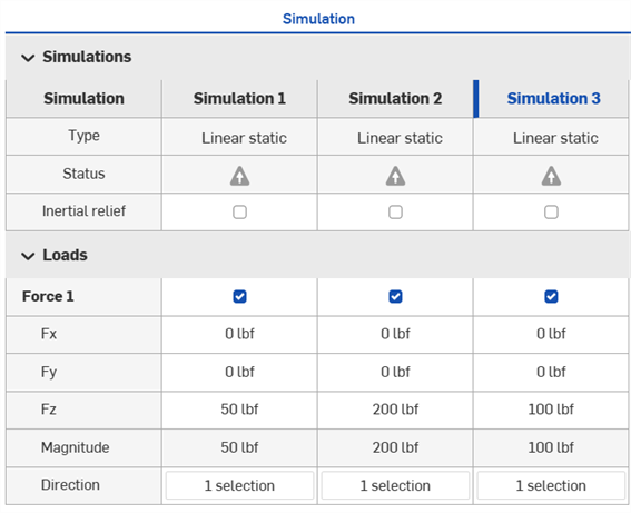
The simulation table is where you manage your simulations and reconfigure loads. Compare between various simulations and review data in the table. The currently active simulation has its column heading highlighted in blue (Simulation 3 in the example below):
Click Add simulation > Add linear static simulation button at the top of the table to add a new simulation:
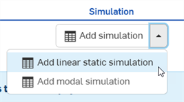
If there are already simulations added in the Assembly, this button is located at the bottom of the Simulation panel.
See Modal simulation for more information on Modal analysis, an additional type of simulation that Onshape offers.
When a new simulation is added, it can be accessed via the Simulation field in the Assembly list. If there are many simulations in this list, begin typing the name of the simulation to auto-search for the correct simulation.
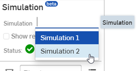
The following outlines the rows and columns found in the Simulation table:
-
Columns - Indicate individually run simulations.
-
Rows - Each row contains an entry for all simulations in the table. The following two rows display information for all the loads found below:
-
Type - Indicates the Simulation type; currently limited to structural linear static analysis and modal analysis.
-
Status - Displays a warning icon
 when the simulation is not correct or is missing information. Displays a gray exclamation
 icon if the simulation is ready but no results are shown. Displays a green checkmark
 when the simulation is successfully run.
-
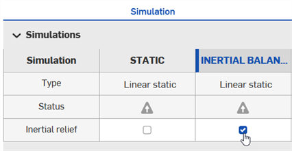
Inertial relief - Check to simulate a dynamic event as though it existed in a state of perpetual equilibrium by shifting from an inertial reference frame to an accelerated frame of reference. See Running a linear static simulation with inertial relief for more information.
-
- Load name - The load name derived from the Load dialog's editable load label.
- Fx - Load component (value) along the x-axis of the associated Mate connector.
- Fy - Load component (value) along the y-axis of the associated Mate connector.
- Fz
- Load component (value) along the z-axis of the associated Mate connector.
(The load magnitudes differ based on which type of load is used. Fx, Fy, and Fz are used for Force load types.)
- Magnitude - Non-editable field that displays the total magnitude value derived from all 3 associated Mate connector axes (Fx, Fy, and Fz).
- Direction - Shows the load direction. Double-click the cell to open the Load dialog with focus on the Load direction field. Select a new Mate connector in the graphics area to update the load direction, and/or click the arrow to reverse the load direction.
Editing in the Simulation table
You can perform many tasks directly in the simulation table:
-
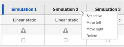
Right-click on the Simulation column heading to do the following:
-
Set active - Only one simulation can be active at a time. Use Set active to make the current simulation active. When a simulation is active, its heading text is blue:
-
Delete - Deletes the Simulation from the table:
-
Move left/right - Move the current Simulation column to the left or to the right.
-
-
To change the name of the Simulation, double-click on the title and enter a new name:
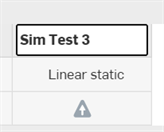
-
Click to disable the checkmark in the simulation column's Load table cell to disable loads for that simulation. Re-check to re-enable the loads again:
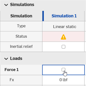
-
Double-click the Fx/Fy/Fz load component cell in the table to enter a new load value:
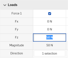
-
Double-click the Direction cell in the simulation column to open the Load dialog with focus on the Load direction field. Select a new Mate connector in the graphics area to update the load direction, and/or click the arrow to reverse the load direction.
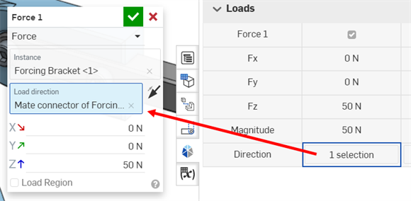
If results were previously shown, click Show results in the Assembly list to view the simulation results again:
Below the table are the Simulation settings. These are subdivided into two main areas: Legend and Connectivity method and visualization. Both are outlined below:
Legend
-
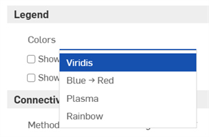
Colors - Switch between the following four color options for the stress/displacement scale:
-
Viridis - Ranges from dark blue (least stress/displacement) to bright yellow (most stress/displacement), with cyan and green in the middle range. This is the default scale.
-
Blue → Red - Ranges from light blue (least stress/displacement) to dark red (most stress/displacement).
-
Plasma - Ranges from dark blue (least stress/displacement) to bright yellow (most stress/displacement), with purple and pink in the middle range.
-
Rainbow - Uses all values in the color spectrum; ranges from blue (least stress/displacement) to Red (most stress/displacement). This is the scale that is most familiar to users of other simulation software.
-
-
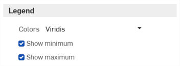
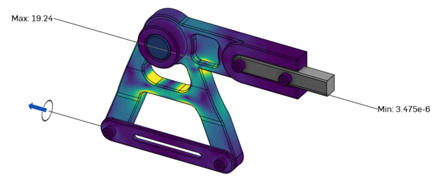
Show minimum (not available for Modal simulation) - Check to display the minimum value of all viewed parts measured by the current simulation (von Mises stress, Signed von Mises stress, Safety factor, Max principal stress, or Displacement).
-
Show maximum (not available for Modal simulation) - Check to display the maximum value of all viewed parts measured by the current simulation (von Mises stress, Signed von Mises stress, Safety factor, Max principal stress, or Displacement).
See Result options for more information.
Connectivity method and visualization
This area is where you set up the connectivity method for simulations and view connections between instances in the Assembly:
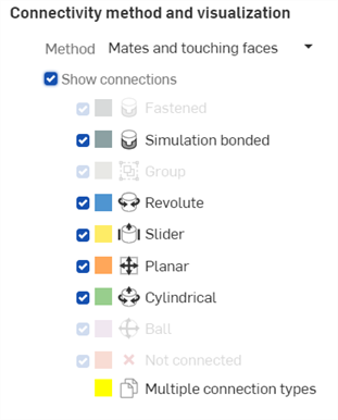
-
Method - The method used by the simulation to determine how instances in the Assembly are connected (bonded). The method chosen drives the simulation and simulation results. Options are:
-
Mates and touching faces - Both Mates and any touching faces are viewed as bonded by the simulation. This is the default method. Anywhere two instances touch, they interact in some manner. If Mates or a Group exist between those two instances, the simulation honors whatever kinematic relation is defined by them. If no Mates or Group exists, the simulation treats those regions as bonded (the same as a fastened Mate or Group). This method is useful when initially constructing your model; it allows you to systematically add Mates to your model one at a time, and ensures the simulation remains sufficiently constrained.
-
Mates - With this method, all simulation interactions are taken strictly from Mates or Groups present in the model. Any non-Mated/Grouped instances that touch each other are treated as independent bodies.
-
Bond all touching faces - With this method, all Mates, including all Mate Simulation connections, are ignored. Any region of any instance that touches any region of any other instance is treated as bonded. This is the same behavior as adding all Assembly instances into a single Group and suppressing all Mates. Though this artificially stiffens your model, it obtains immediate simulation results, and is the simplest workflow option.
During simulation, it is possible to have non-Mated instances pass through each other.
-
-
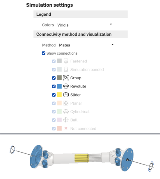
Show connections - When checked, this displays the connections between instances in the Assembly graphics area as a diffuse fill color-coded by connection type, so that bonded connections are visualized. Any connection type not present in the model is grayed-out. To isolate a specific connection, systematically uncheck each connection type and/or suppress Mates in the Assembly list.
-
Fastened - When checked, Fastened Mate connections are shown. Fastened Mate connections bond two instances across their interface. Instances deform in unison; no relative displacement is permitted across this interface.
-
Simulation bonded - When checked, simulation bonded connections are displayed. Simulation bonded connections are only possible when Method is set to Mates and touching faces or Bond all touching faces. Simulation bonded acts the same as Fastened.
-
Group - When checked, instance groupings are displayed. All instances within a Group connection are treated as though Fastened across each of their interfaces.
-
Revolute - When checked, Revolute Mate connections are displayed. Revolute Mate connections prohibit any relative motion between two instances across their interface, except for rotations about the Revolute center axis.
-
Slider - When checked, Slider Mate connections are displayed. Slider Mate connections prohibit any rotational relative motion between instances across their interface, as well as translational relative motion across the interface, except along a singular (sliding) direction.
-
Planar - When checked, Planar Mate connections are displayed. Planar Mate connections prohibit any rotational relative motion between instances across their interface, as well as any out-of-plane translational relative motion between instances.
-
Cylindrical - When checked, Cylindrical Mate connections are displayed. Cylindrical Mate connections allow rotational/translational relative motion between instances across their interface about/along the cylindrical center axis. All other relative motion is prohibited.
-
Ball - When checked, Ball Mate connections are displayed. Ball Mate connections prohibit any translational relative motion between instances across their interface, though they allow any and all rotational relative motion about the ball center point.
-
Not connected - When checked, instances that are within simulation interaction proximity and could be connected but are not (they do not have any prescribed simulation interaction) are displayed and color-coded red.
-
Multiple connection types - This is only displayed if multiple connection types are in use in the same location, as is often the case when multiple instances are joined closely together. These connections are color-coded yellow. See the example further below.
This category considers Not Connected to be a valid interaction type. For example, if the corner of a instance A is fastened to instance B and adjacent to instance C, but no interaction is defined between A and C, then instance A's corner is marked as a Multiple connection type (colored yellow), unless either the Fastened or Not Connected visualization box is unchecked.
If two adjacent instances are not meant to interact with each other, disregard the Not connected visualization. Conversely, the ability to identify any Not connected instances is useful as you build up your Assembly Mates for the first time by showing you missing connections.
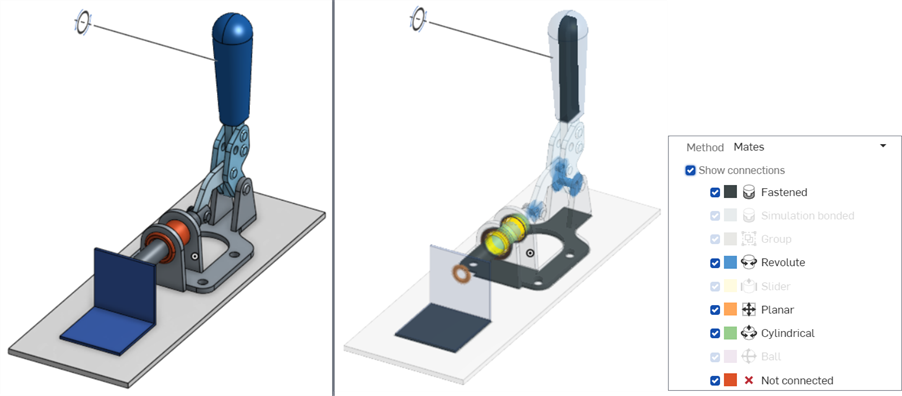
Example with Show connections unchecked (left) and checked, with all connection types checked (right).
When a type of connection does not exist in the assembly, the connection type is grayed out. If it exists, it is available to check (show) or uncheck (hide).
If multiple connection types are in use in the same locations, they are color-coded yellow:
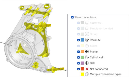
In this example, both Mate and Not connected types are displayed simultaneously.

In these examples, only Mate connections are shown (left) and only the Not connected type is shown (right).
-
The Mate Simulation connection option is found at the bottom of all Mate dialogs (except Pin slot, Parallel, Tangent, and Width Mate dialogs). This option provides a greater degree of precision and control over which regions are bonded by limiting the Mate’s effect over a specific region, as opposed to having the Mate bond anywhere two mated instances touch.
Check the Simulation connection and enter the Faces to connect:
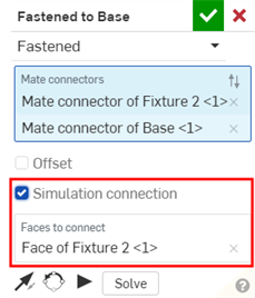
Simulation connection has no impact on your typical Assembly modeling behavior; it is only seen during simulation. Use the Connectivity method and visualization to inspect the difference.
Using Bond all touching faces as the connectivity method overrides all Mate Simulation connections.
This workflow assumes you have a completed CAD model in an Assembly tab, with the instances mated and the assembly sufficiently constrained. For this simulation example, a Caliper bracket assembly is used. It contains 4 instances and 4 bolts. The 4 instances are: the Caliper bracket, Axle, Connection bracket, and Forcing bracket:
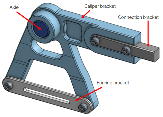
Before creating a simulation, the following two criteria must be met:
-
At least one instance must be fixed in the Assembly. This is the instance on which the load is bearing. Right-click on the Axle and select Fix from the context menu. Do the same for the Connection bracket instance:
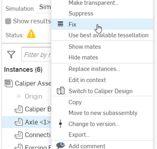
-
All instances (including standard content) used in the simulation (except those that are fixed) require a material assigned to them. Do one of the following:
-
Open the Assembly BOM table. Double-click on the Material field for the associated instance row (in this example, the Caliper bracket), and select a material from the Material dialog.

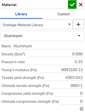
-
From the Part Studio, right-click on the part in the Parts list, and select Assign material. Then select a material from the Material dialog:
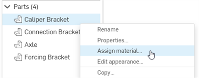

-
To create and load a simulation:
-
Visualize the Mate connections in the assembly. Open the Simulation panel and check Show connections. If desired, select an alternate Method to determine how instances in the assembly are connected (bonded together). Connectivity method and visualization can be changed at any point before, during, and after the simulation:
-
From the Assembly tab, select one of the six load tools along the top right of the Assembly toolbar. In this example, Force is selected:
The Force dialog opens:
-
Select an Instance. Only one instance can be selected. Multiple instances are not currently supported; however, you can create multiple simulation loads in the same assembly. For this example, the Forcing bracket instance is selected.
-
Select a Load direction. Select an existing Mate connector, or click on a location to create a new Mate connector that drives the load direction. Click the reverse arrow icon
 to reverse the direction of the load. For this example, a Mate connector is added to the edge of the Forcing bracket, with the Z axis pointing left:
-
Enter the Magnitude for the load along any of the three axes (X, Y, and/or Z). These are the forces borne on the fixed instance. For this example, a load of 50 N is applied to the Z axis:
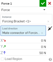
-
By default, the load is applied to the whole body. If desired, optionally check Load region, and select Faces to load, to narrow the load to a specific region.
-
Click the green checkmark
 to close the Force dialog.
-
Check Show results. As the results are calculated, a blue progress bar indicates the time remaining before the final calculation displays. Early iterations are displayed in the stress scale. When finished, the blue progress bar reads complete, and then a green checkmark is placed next to the Status signifying the calculation (convergence) is complete:
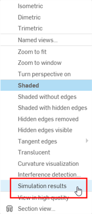
Alternatively, you can select Simulation results from the View tools
 menu:
menu:
The simulation converts the Assembly geometry to a simulation mesh, and begins the first of five adaptive passes before converging on a result. Intermediate updates are streamed through the browser, giving you early simulation results. When results are finalized, the Scale is visible at the top of the screen, and the stress plot overlays the loaded instances with a color gradient in the graphics area. Simulation results are also temporarily cached.
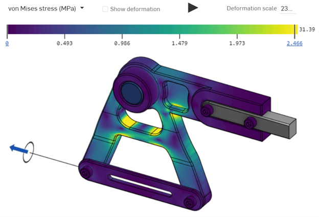
-
Select from 5 different result metrics. For more information, see Simulation results and color scale:

-
Hover your mouse over the instance in the graphics area to display a numerical readout next to the cursor. This indicates the stress or displacement amount of the instance located under the cursor:
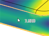
-
To animate the simulation, click the Play toggle above the color scale. To stop playback press the Stop toggle:

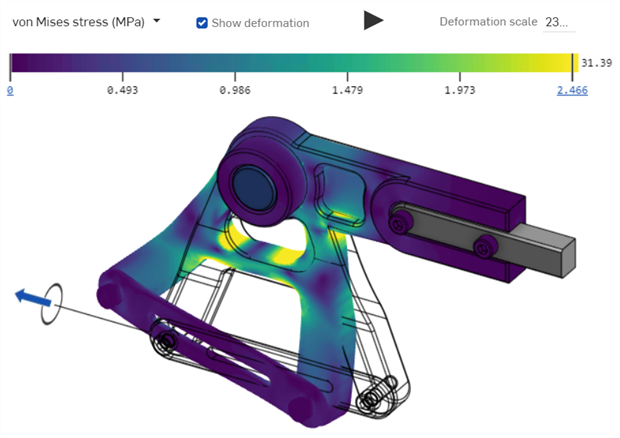
The simulation load result with Show deformation checked. The deformation is overlaid with a view of the original assembly as a wire frame.
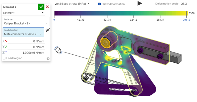
The following displays an alternate simulation load using Moment, selecting the Caliper bracket as the instance, and then selecting the Mate connector at the center point of the axle as the Load direction. A load of 1.000e+6 N*mm is applied along the Z axis, and Show deformation is checked in the legend. This allows you to view both the original assembly and resultant deformation at the same time:
Linear static simulation with inertial relief is a means of simulating a dynamic event as though it existed in a state of perpetual equilibrium by shifting from an inertial reference frame to an accelerated frame of reference. The simulation can now be run while the assembly instances have free motion (are not fully constrained).
Analyze the stresses and strains experienced throughout each of the assembly bodies, within their accelerated reference frame, as they traverse their rigid body motion.
Steps
Before creating a simulation it is recommended to familiarize yourself with the Basic simulation workflow.
-
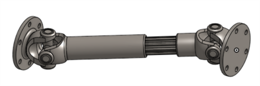
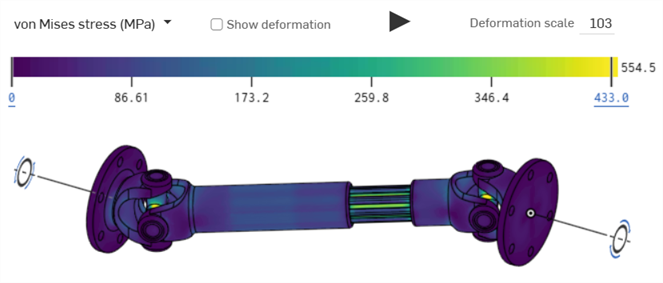
Insert one or more instances into an Assembly. In the following example, a drive shaft is used:
-
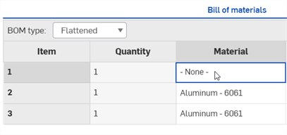
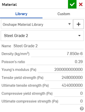
All instances (including standard content) used in the simulation (except those that are fixed) require a material assigned to them. Do one of the following:
-
Open the Assembly BOM table. Double-click on the Material field for the associated instance row, and select a material from the Material dialog.
-
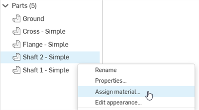
From the Part Studio, right-click on the part in the Parts list, and select Assign material. Then select a material from the Material dialog:

-
-
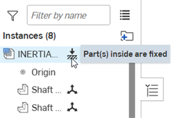
Optionally, fix one or more instances:
-
Optionally, apply mates and touch-interactions until the model is fully constrained. Then click Show connections to review boundary conditions:
-
Apply one or more loads:
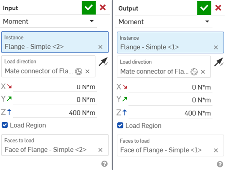
Two Moment loads; the Input moment load is applied to the flange on the right, and the Output moment load is applied to the flange on the left
-
Open the Simulation panel and check Inertial Relief:
-
Checking the Inertial relief checkbox:
-
Identifies all rigid body modes of the assembly (a partial Modal analysis is performed).
-
Considers each rigid body mode as a (potential) basis function for the application of restorative body loads (combination of Forces and/or Moments)
-
Applies the proper proportion to each potential load/mode pair such that the restorative body loads bring the Assembly into Static Equilibrium with the Applied Loads
-
Conducts Linear static analysis using a combined set of applied and restorative loads
-
-
Check Show Results:
The results are displayed:
Notes
-
Inertial relief does not require any parts be fixed in the Assembly for the simulation to be successful.
-
Inertial relief applies only to Linear static simulation. It does not apply to Modal simulation.
Example
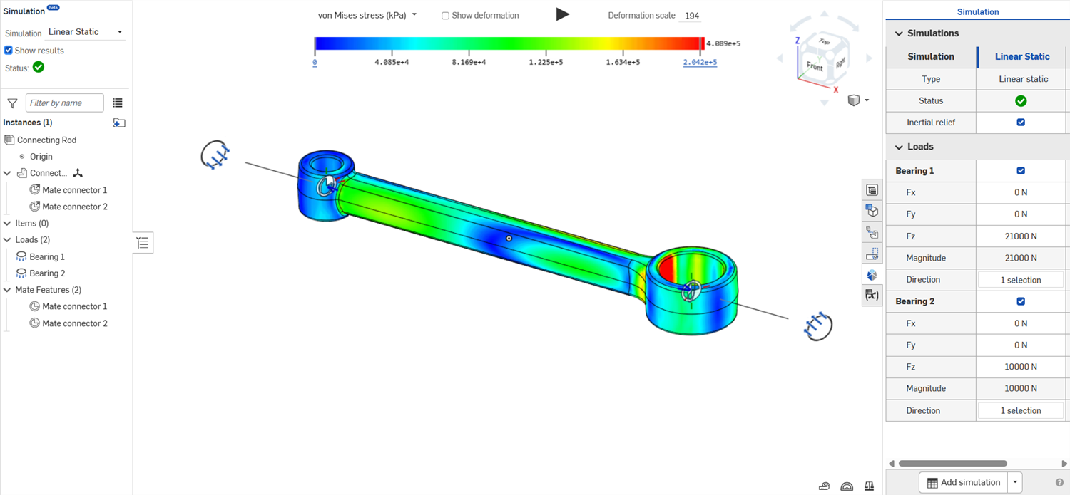
The following shows a Connecting Rod assembly. The Connecting Rod instance is not fixed. 2 Bearing loads are applied to the instance, and Inertial relief is checked. The results are displayed after Show results is checked:
Once a simulation is created, create alternate simulations and compare between them.
-
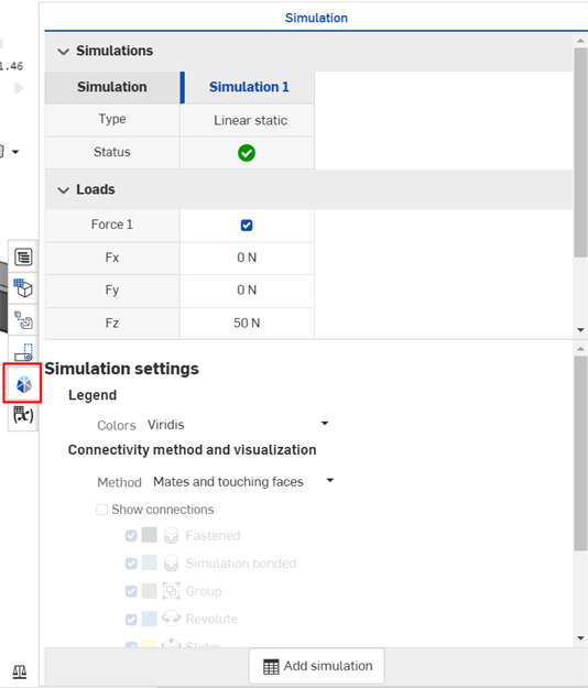
Open the Simulation panel at the far right of the screen (outlined in red below):
-
Click the Add simulation button at the bottom of the screen. You can add multiple simulations, which show up in columns in the Simulation table along the top, and edit their loads directly in the table:

-
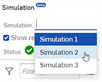
To set a Simulation to active and show its results on-screen, right-click on the Simulation title in the table and select Set active from the context menu (shown in the first image below). Alternatively, select the simulation from the Simulation dropdown in the Assembly list at the left side of the window to make it active (shown in the second image below):

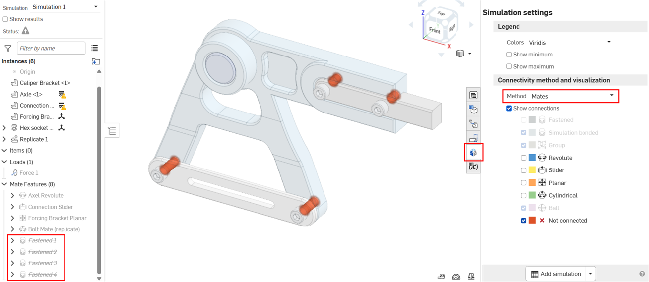
The following example outlines how to use an alternate method to solve a simulation. For this example, the same Caliper bracket assembly is used from the Basic workflow section above.
-
In the example below, Mates are used as the connectivity Method, and the Fastened Mates that connect the bolts between the Caliper bracket and Forcing bracket are suppressed in the Mate Features list. There is nothing to constrain the Forcing bracket to the Caliper bracket:
-
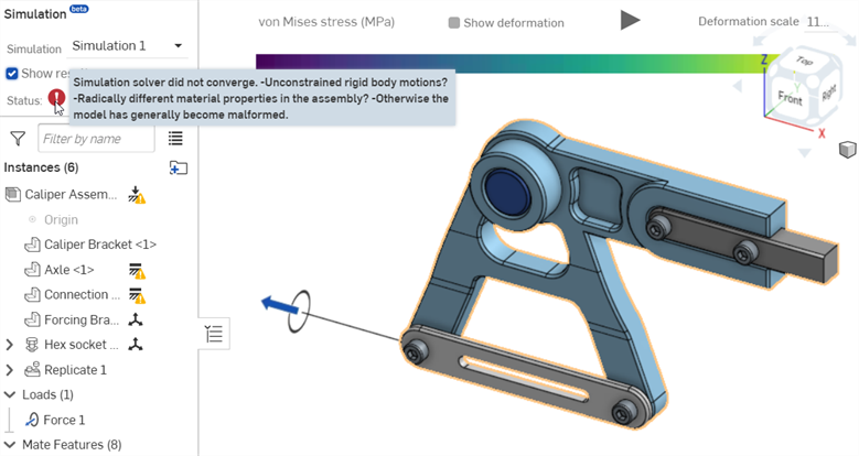
Check Show results in the Simulation area at the top left. The Simulation solver does not converge due to unconstrained rigid body motions:
-
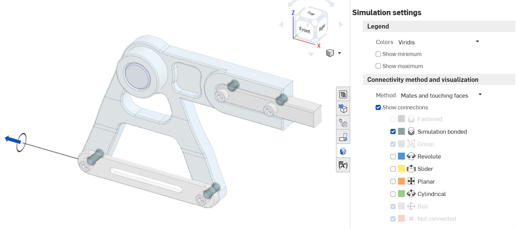
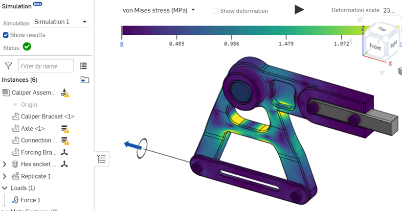
Change the connectivity Method to Mates and touching faces. The touching faces between the bolts and Caliper bracket are treated as Simulation bonded; the simulation is now fully constrained and can be solved:
-
Check Show results in the Simulation area at the top left to view the simulation results:
-
Onshape Simulation is based on a proprietary, adaptive-refinement implementation of the well understood finite element method. This approach is optimized to produce highly performant and accurate results for Parts of arbitrary shape and detail. However, the drawback to this universally robust solution is that special geometry classes, which are better served by special element types, may presently require too many computing resources to reasonably solve. This is most commonly observed among thin-walled structures such as sheet metal parts or thin-walled frames. Onshape Simulation aims to enhance this performance in the future. At this time we do not recommend using simulation for geometries with aspect ratios above 100:1.
-
When assigning materials to any non-fixed instances/parts used in simulations, their Density, Poisson's ratio, Young's modulus, and Tensile yield strength properties must be provided.
Safety factor results are not provided for parts that do not have Tensile yield strength material property defined. In addition, materials with a Poisson's ratio of either -1.0 or 0.5 cannot be simulated.
Create your own library with your own data defined or use standard materials (for example, 6061, Steel, ABS, etc.). Some materials in the standard library (for example, Balsa wood, Graphite, Silicone rubber) do not work with simulations.
-
Overridden mass values are ignored in simulation results.
-
The following Mates are not translated, and therefore, not supported by simulation: Tangent Mate, Pin Slot Mate, Parallel Mate, and Width Mate. Relations (Gear relation, Rack and pinion relation, Screw relation, and Linear relation) are also not supported.
-
Interactions between instances are inferred wherever two instances touch. If two instances are not touching (or within very close proximity), they do not interact with one another when simulated.
-
By default, any two instances which touch and are not otherwise Mated, are assumed to be bonded together. If Mated, then the bonded behavior is overruled by the kinematic relation prescribed by the Mate.
-
Any range prescribed in a Mate has no effect on the simulation. Each simulation cares only about the initial starting conditions prescribed by the Mates; translations and rotations which occur thereafter follow as a direct consequence of the linear relationships assumed in the linear static analysis.
-
By default, interactions between instances extend between small gaps designed into the model. Onshape simulation performs well whether instance interfaces are designed flush, or whether machining gaps/tolerances are included.
-
If there are regions between parts that are near enough one another to infer a connection and you do not want them connected, use the Mate Simulation connection to explicitly define the interaction. This is particularly useful if your design has any wedge-shaped gaps, where, at the widest area of the wedge, interaction is unlikely to occur. The nearer the wedge’s point, the more likely an interaction will bridge the gap.
-
Unless you are applying Inertial relief, at least one instance must be fixed in a simulation. It is a common practice to create a "base" assembly instance which acts as the ground. Fix the ground instance, and then mate any neighboring instances to this ground.
-
Ensure the assembly is fully constrained kinematically, otherwise apply Inertial relief to run the simulation. Though tolerant of under-constrained assemblies, particularly if the loaded system is in static equilibrium, the simulation may not converge unless the model is fully constrained.
-
Composite parts are not currently supported in Onshape Simulation.
-
In certain cases, the simulation cannot be run and the message Simulation cannot be completed. Try reducing the number of instances appears. This is due to one of the following:
-
The simulation uses 100 or more instances or too many instances are grouped or bonded. Try reducing the number of instances and groups, or avoid using Mates and touching faces or Bond all touching faces connectivity methods.
-
Simulation model complexity exceeds server memory limits. Consider simplifying the Assembly.
-
For an additional Learning center resource, see Introduction to Onshape Simulation (Onshape account required).