![]()
Insert a custom table into a drawing. Custom tables tabulate Part Studio data. Updates to the Part Studio update the data in the custom table. See Updating a Drawing for more information.
A custom table is comprised of 2 orthogonal components:
-
A custom table definition in a Feature Studio.
-
A Part Studio to tabulate data.
A custom table definition can be applied to any Part Studio.
When a custom table is inserted into a drawing, the Part Studio's tabulated data applies to the entire Part studio, and not only parts inserted or referenced in the drawing.
Custom tables allow you to view specific information about a Part Studio using FeatureScript.
Open the Custom tables panel in a Part Studio. Click Add custom tables, or select a previously added table from the dropdown to view one.
To insert a custom table into a drawing, click Custom table in the Drawing toolbar. Select a Part Studio to populate the table. Part Studios already in the drawing appear in the dropdown, but the Part Studio does not need to be present in the drawing. Click the Add button to select a Part Studio that is outside the drawing. Click the Insert button to select a new custom table, or select an existing table from the dropdown. Select an Order and fixed corner.
Custom tables apply to the entire Part Studio, not just the parts inserted or referenced in the drawing.
-
Click
the Custom table icon on the Drawing toolbar (
 ).
).
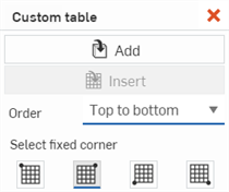
- The cursor becomes a table icon and the Table dialog opens:
- If no Part Studio is inserted into the dialog, click the Add button to select one:
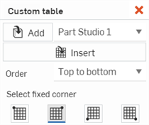
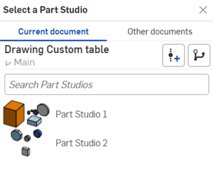
If a Part Studio is already inserted into the drawing, it is populated with that Part Studio. To select a different Part Studio, Click the Add button (first image below) and select a new Part Studio from the Select a Part Studio dialog (second image below):
- If no Part Studio is inserted into the dialog, click the Add button to select one:
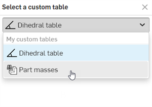
- Click the Insert button. The Select a custom table dialog opens. Use the table dropdown to select the custom table, and then click the Done button.
- (Optional) Order - Specify the table row order, either Top to bottom or Bottom to top.
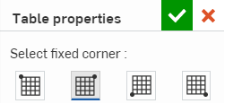
- (Optional) Select fixed corner - Select which corner of the table to use as the anchor point at the bottom of the dialog:
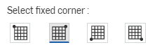
- To place the table, click anywhere on the sheet to set its location (anchored by the fixed corner selected above).
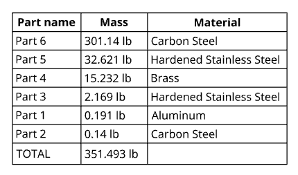
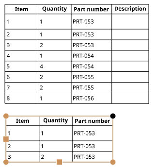
Example of a custom table inserted into a drawing
The default fixed corner in Onshape is the upper right of the table.
Tips
-
There is no need to click directly on the point once it is visible. While moving the mouse to place the table, you'll notice thin, dashed lines as the cursor passes near other entities. These are inferencing lines that you can align the table to; simply click when you see the line appear to align the table to that line.
-
Once the table is placed, double-click in any cell to open the Note panel for editing text.
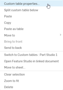
After a table is created and the Table dialog is closed, you are able to hover over a table to activate grab points:
- Drag any of the square mid-points (top, bottom or side) to resize the table; cells are resized relative to each other.
- Drag any of the corner points to move the table.
- Double-click on the mid-points of a table to automatically size to fit the contents of the table.
-
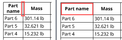
To resize the rows and columns on both sides of the cell edge, without resizing the table, hover your cursor over the top or right cell edge, and when the cursor changes to a double-sided arrow, click and drag the line and drop it in the new location. To resize only the row or column of the selected cell, and have the rest of the table resize, hover your cursor over the bottom or left cell edge, and when the cursor changes to a double-sided arrow, click and drag the line and drop it in the new location.
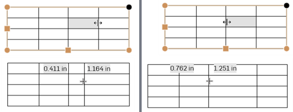
Resizing both columns on either side of the dividing edge, without resizing the table (left two images), and resizing only the selected cell's column and having the rest of the table resize accordingly (right two images).
- Drag a corner of the table to snap to a corner of the drawing; when you see the red snap point, let go of the mouse button to place the table.
- Double-click on a column or row divider to size the column or row to the text within:
Double-click on the divider to the right of the first column to resize that column to fit the contents
-
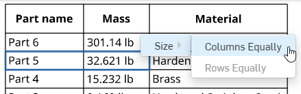
Select 2 or more cells, either horizontally or vertically, right-click and select Size > Columns equally or > Rows equally to resize either an entire row or column equally to be of the same size.
-
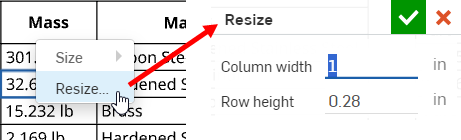
To resize the column width or row height numerically, select a cell, right-click and select Resize to open the Resize dialog. Enter the new Column width and Row height measurements.
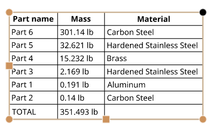
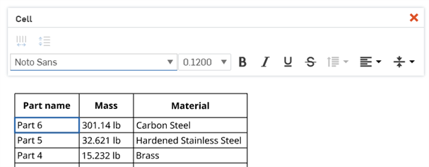
- Single-click in a table cell or row to activate the Cell formatting panel. The cell outlined in blue (Part 6) is the selected cell:
- Double-click your previously selected fixed corner to activate the Table properties dialog, where you are able to edit your selected fixed corner by simply clicking on the box of your choice. Click the checkmark in the top right corner of the dialog to set your changes:
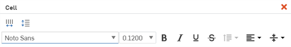
Cell formatting panel
Double-click in a table cell to open the cell formatting panel:
![]()
- Shift+click to select more than one cell
- Select multiple cells that are adjacent to each other
- Click in a cell to select; use the grab points to resize the cell's row or column
When more than one column is selected, you can also:
![]() Size columns equally
- Resize all selected columns to the average width
Size columns equally
- Resize all selected columns to the average width
When more than one row is selected, you can also:
![]() Size rows equally
- Resize all selected rows to the average height
Size rows equally
- Resize all selected rows to the average height
All of the text formatting commands available in the Note panel are also available in the cell formatting panel (font, font size, bold, italics, underline, strikethrough, line spacing, vertical alignment, and horizontal alignment).
Tips
-
When using Date properties in table cells, the UTC time zone is used. This could potentially lead to a situation where a date is displayed as tomorrow, for example.
-
To set formatting defaults for custom tables, see Drawing Properties > Tables.
Copy table cells from Onshape drawing tables, and paste them into Excel, Google Sheets, or an Onshape drawing as a new, editable table.
Copying an Onshape drawing table into Excel or Google Sheets is supported on Google Chrome, Mozilla Firefox, and Microsoft Edge. Safari is not supported. Copying text may yield different results due to platform limitations.
-
Open an Onshape drawing table.
-
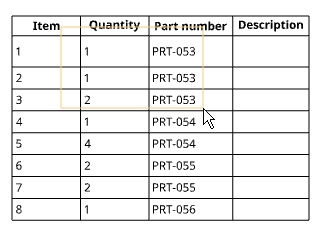
Click and drag to select the cells to be copied. The selection is shown with a yellow highlight.
-
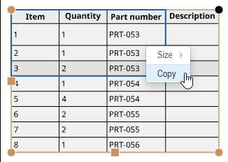
Release the selection. The selected cells are highlighted in blue. Press ctrl+c, or right-click and select Copy.
-
Open the drawing or external sheet into which you want to paste the content.
-
Right-click the location you want to paste the table and select Paste (or press ctrl+v).
If using Onshape in a Mozilla Firefox browser, use ctrl+v to paste the table. Using the Paste command from the context menu is not supported.
There are two ways to open the Custom table properties dialog, listed below:
- Right click on the table and select Custom table properties.
-
Double click on any corner of the table.
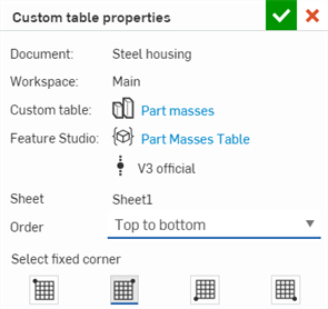
The Custom table properties dialog opens:
-
Document - The name of this document
-
Workspace - The name of this document's workspace
-
Custom table - The name of the custom table. Click the link to open the custom table's associated Part Studio tab.
-
Feature Studio - The name of the Feature Studio tab. Clicking this link opens the Feature Studio tab containing the custom table's FeatureScript. The Feature Studio's version is also listed below the link.
-
Sheet - The name of the current Drawing sheet.
-
Order - The table row order, where you can select either Top to bottom or Bottom to top.
-
Select fixed corner - Selects which corner of the table to use as the anchor point.