Decal
Place an image decal on a planar surface or cylinder.
The Decal feature places an image on a cylindrical or planar face from within a Part Studio.
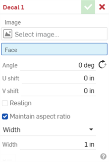
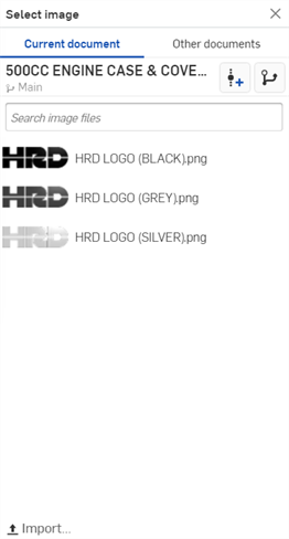
Select the Decal feature from the Feature toolbar. Click Select image to browse the Current document, Other documents, or your machine for an image. Select the desired image.
Click the cylindrical or planar face on which to place the decal.
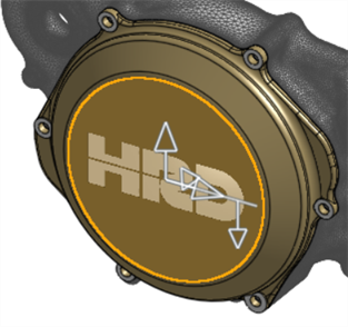
To rotate the image, use the image’s triad manipulator or enter an Angle in degrees. Flip the angle with the Angle opposite direction icon.
To relocate the image on the selected face, either use the triad manipulator to drag the image in the U shift and V shift directions or enter values manually.
To select a new origin point for the decal, check the option Realign.
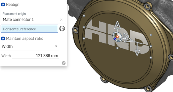
Select a placement origin with an explicit or implicit Mate connector. When using an implicit Mate connector, click the Mate connector icon to edit the implicit Mate connector. The Decal’s origin uses the Mate connector’s Z-axis.
Once a placement origin is selected, image reference points provide a way to relocate the image placement in relation to the Decal origin. Selecting a reference point aligns the decal’s placement origin to that point.
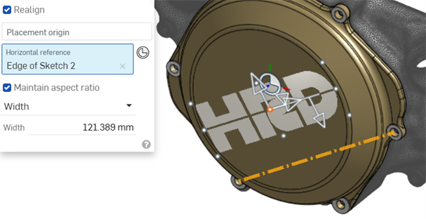
Optionally, provide a Horizontal reference. Click a face or edge to define the horizontal position of the Placement origin, or toggle on Select Mate connector to choose a Mate connector. Use the horizontal reference to rotate the decal or align the decal with an angled edge of the model.
To resize the Decal, modify the width and height by dragging the resize arrow in the graphics area or entering values in the dialog. With Maintain aspect ratio enabled, adjusting the Width or Height value adjusts the corresponding value to keep the decal's width and height locked together.
Disable Maintain aspect ratio to modify the Width and Height values independently. Enter the Width value to modify the width of the decal in a length unit. Enter the Height value to modify the height of the decal in a length unit.
Click the checkmark to accept the new decal.
- Select the Decal icon () on the Feature toolbar.
- Click Select image to open the Select image dialog. Do one of the following:
Select an image from the Current document or Click Other documents to browse and select an image from an external document, to load it into the Image field in the Decal dialog.
Click Import at the bottom of the dialog to open an image from a location on your machine. Then select the image to load it into the Image field in the Decal dialog.
- Select the face on which to place the decal. Currently, only planar or cylindrical faces are supported:
-
Enter an Angle for the decal, in degrees. Click the Angle opposite direction icon () to flip the angle in the opposite direction.
-
Enter a U shift value for the first direction in a length unit
-
Enter a V shift value for the second direction in a length unit.
- Optionally, check Realign to align the decal to a new location via the Placement origin and Horizontal reference fields and/or the transform manipulator in the graphics area.
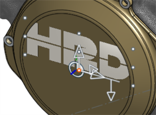
- The Placement origin field realigns the decal's center origin to a Mate connector's Z-axis. Use your mouse to select an explicit Mate connector (shown below) or hover over the graphics area with your mouse to create an implicit Mate connector.
- When the Placement origin is selected, the image displays 9 reference points surrounding the image. Optionally, select any one of these reference points to align the decal's Placement origin to that point.
- The Horizontal reference field realigns the decal's horizontal axis to an edge. Use your mouse to select an edge in the graphics area. This is useful if you would like the decal to align to an angled edge of your model (as shown below):
Use the transform manipulators to alter the decal's position and size:
Use the U or V manipulators to move the decal left/right or up/down, respectively.
Use the angle manipulator to rotate the decal between 0 and 360 degrees.
Use the size manipulator to resize the decal larger/smaller, while maintaining its aspect ratio.
- The Placement origin field realigns the decal's center origin to a Mate connector's Z-axis. Use your mouse to select an explicit Mate connector (shown below) or hover over the graphics area with your mouse to create an implicit Mate connector.
- Do one of the following:
- With Maintain aspect ratio checked:
- Select either Width or Height from the dropdown.
- Enter a value in the Width or Height field.
The decal is resized in both directions relatively; Both width and height of the decal remain locked together relative to each other.
- Uncheck Maintain aspect ratio:
- Enter the Width value to modify the width of the decal in a length unit.
- Enter the Height value to modify the height of the decal in a length unit.
- The decal is resized in both directions independent of each other; Both width and height of the decal are not locked together.
- With Maintain aspect ratio checked:
- Click the checkmark to accept the new decal.
If the Face is selected prior to clicking the Decal feature on the Feature toolbar, that face is pre-populated in the Face field in the Decal dialog.
Surfaces have three directions: U, V, and Normal. The U and V represent the X and Y directions of the surface.
Decals support image transparency. This enables you to create transparency over portions of your model. For example, you could create transparency in the image so that it shows through Hole features in your model.
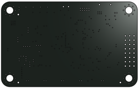
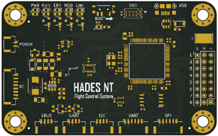
The following example shows a PCB board without a decal (in the first image) and the decal applied (second image). The decal image used is transparent where the holes, vias, and such in the board are located:
-
If you wish to adjust the decal's placement and dimensions non-numerically, when the decal is placed, the transform arrows in the graphics area allow you to move the decal along the X- and Y-axis and rotate the decal about the placement origin point. The triangle allows you to increase or decrease the decal's size.
-
By default, when the decal is placed, it is automatically adjusted to fit the dimensions of the face.
-
Supported decal file formats: PNG, JPG, GIF, and BMP.
-
If you change a surface with a decal to anything other than a planar or cylindrical face (for example, changing to a conical face), this will cause an error to occur on the decal feature.
-
Decals are visible in Drawings only when shaded view is shown. See Show/Hide shaded view.
-
Decal features are supported in Render Studio. See Working with decals.
- Optionally, tap the Tab manager icon () at the bottom left corner of the screen, then the plus () icon. Select an image to import into the current document. The image populates the Select image list.
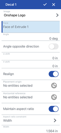
- Tap the Decal icon ().
- Tap Select image to open the Select image dialog. Do one of the following:
- Select the image you added from Step 1 above.
- Select an image from the Current document or tap Other documents to browse and select an image from an external document, to load it into the Image field in the Decal dialog.
- Tap the face on which to place the decal. Currently, only planar or cylindrical faces are supported.
-
Enter an Angle for the decal, in degrees. Tap the Angle opposite direction toggle to flip the angle in the opposite direction.
-
Enter a U shift value for the first direction in a length unit
-
Enter a V shift value for the second direction in a length unit.
- Tap the Realign toggle to select a new origin point for the decal.
- The Placement origin field realigns the decal's center origin to a Mate connector's Z-axis. Tap to select an explicit Mate connector or hover over the graphics area with your finger to create an implicit Mate connector.
- When the Placement origin is selected, the image displays 9 reference points surrounding the image. Optionally, tap any one of these reference points to align the decal's Placement origin to that point.
- The Horizontal reference field realigns the decal's horizontal axis to an edge. Tap to select an edge in the graphics area. This is useful if you would like the decal to align to an angled edge of your model.
- The Placement origin field realigns the decal's center origin to a Mate connector's Z-axis. Tap to select an explicit Mate connector or hover over the graphics area with your finger to create an implicit Mate connector.
- Do one of the following:
- With Maintain aspect ratio toggled on:
- Select either Width or Height from the dropdown.
- Enter a value in the Width or Height field.
The decal is resized in both directions relatively; Both width and height of the decal remain locked together relative to each other.
- Toggle Maintain aspect ratio off:
- Enter the Width value to modify the width of the decal in a length unit.
- Enter the Height value to modify the height of the decal in a length unit.
- The decal is resized in both directions independent of each other; Both width and height of the decal are not locked together.
- With Maintain aspect ratio toggled on:
- Tap the checkmark to accept the new decal.
If the Face is selected prior to tapping the Decal feature on the Feature toolbar, that face is pre-populated in the Face field in the Decal dialog.
Surfaces have three directions: U, V, and Normal. The U and V represent the X and Y directions of the surface.
Refer to the Decal transparency and Notes sections for additional Decal feature information.