以模型為基礎的定義 (MBD)
![]()
![]()
![]()
在 Part Studio 中提供此功能
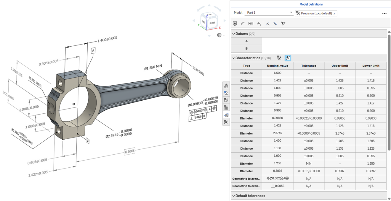
以模型為基礎的定義 (MBD) 指的是在 Part Studio 中標註模型尺寸與建立註記的過程,所以模型會包含定義產品所需的所有資料。透過 MBD,模型將變成驅動所有工程活動的權威來源。此模型可進一步供下游的供應商和各組織使用。
MBD data works in conjunction with Tolerance options, where sketch and feature dimensions are made tolerant, and the Inspection table, where MBD data can be viewed, added, and exported for each part in a Part Studio.
MBD 並非是用來取代工程圖的。MBD 意在採集與延伸模型的產品製造資訊 (PMI) 與基於模型的企業 (MBE) 資訊,以供其他或替代的下游用途。
MBD 的一些特點:
-
尺寸與註記的中繼資料是內嵌在 Part Studio 的模型中的。
-
改善在 Part Studio 中模型上的即時協作。
-
為整個組織的工程師提供單一的真實資訊來源。
-
與下游流程的連結,例如三次元量測儀 (CMM) 檢查。
可以直接從圖形區域中編輯驅動 MBD 草圖與特徵的尺寸。
當檢查表格是開啟時,可以在圖形區域中編輯產品製造資訊,也可以在最初定義這些資訊的草圖與特徵中編輯。
在圖形區域中連按兩下尺寸來編輯公差。如果尺寸參考了「特徵」清單,Onshape 會開啟草圖或特徵以供編輯。如果是使用註記工具列來建立尺寸,請從圖形區域中編輯。當模型與公差變更時,檢查表格會即時更新。
在「特性」表格中,使用兩個切換按鈕來篩選列。一開始會顯示套用了預設公差的註記,並會隱藏來自衍生幾何的註記。僅能修改來源才能更新衍生的註記。
使用交叉強調顯示來快速辨識並找出相關的模型參考。將游標移動至檢查表格的儲存格上暫留以在圖形區域中交叉強調顯示參考的零件、面、特徵與相關的註記。在圖形區域中選擇一個註記,或按一下「基準」或「類型」儲存格來保持強調的顯示。
若要移除註記,請在圖形區域中選擇該註記,然後按下 Delete 鍵。刪除參考了「特徵」清單的註記會從草圖尺寸或特徵值中移除公差選項,並從「特性」表格中移除列。刪除使用註記工具列放置的註記會將其中表格中移除。 無法刪除衍生的註記。
-
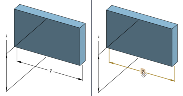
開啟「檢查」面板 (
 ) 來在圖形區域中顯示 MBD 尺寸 (下方左圖)。
 -
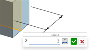
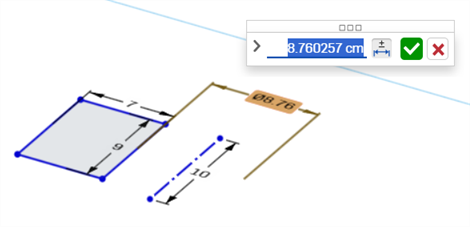
連按兩下與草圖關聯的驅動尺寸上 (下方右圖):
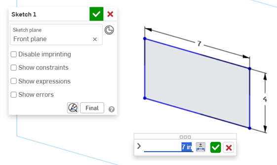
尺寸環境對話方塊開啟,其中有適境的尺寸值。草圖對話方塊也會同時開啟:
-
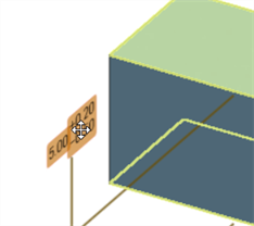
使用鍵盤輸入一個數值,或使用上/下方向鍵來在尺寸環境對話方塊中增加值。草圖會隨著值的調整而動態更新。
如果輸入數值,請按下 Tab 鍵來查看草圖值的更新。
-
按下鍵盤上的 Enter 鍵,或按一下尺寸環境對話方塊中的核取記號 (
 ) 來關閉這個對話方塊:
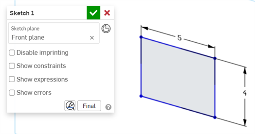
-
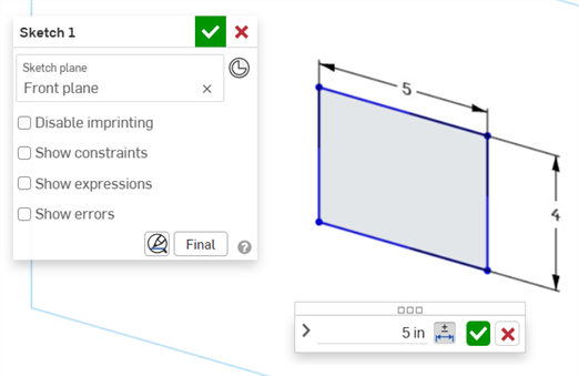
按下草圖對話方塊中的核取記號 (
) 來接受新的草圖值。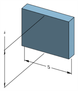
編輯後的草圖尺寸調整了模型尺寸
-
開啟「檢查」面板 (
) 來在圖形區域中顯示 MBD 尺寸 (下方左圖)。 -
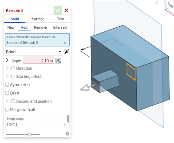
連按兩下與特徵關聯的驅動尺寸上 (下方右圖):
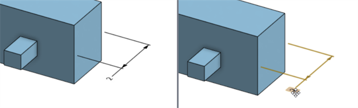
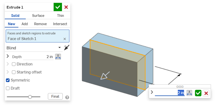
尺寸環境對話方塊開啟,其中有適境的尺寸值。相關的特徵對話方塊也會同時開啟 (在這個範例中的擠出):
-
使用鍵盤輸入一個數值,或使用上/下方向鍵來在尺寸環境對話方塊中增加值。模型與特徵對話方塊中的值都會隨著這個值的調整而動態更新。
如果輸入數值,請按下 Tab 鍵來查看值在特徵對話方塊中的更新。
-
按下鍵盤上的 Enter 鍵,或按一下尺寸環境對話方塊中的核取記號 (
) 來關閉這個對話方塊: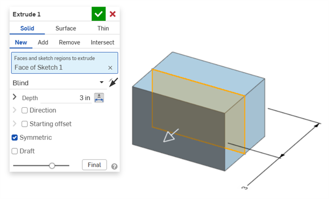
-
按下鍵盤上的 Enter 或按一下特徵對話方塊中的核取記號 (
) 來關閉這個對話方塊: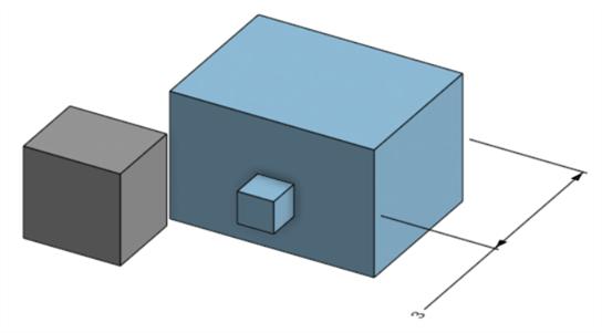
編輯後的特徵尺寸調整了模型尺寸
刪除一個註記:
-
在圖形區域中選擇註記。
-
按下 Delete 鍵。
-
系統會從圖形區域與檢查表格中刪除註記。
如果註記是一個草圖或特徵尺寸:
-
則會刪除尺寸的公差選項值。
-
會取消選取公差選項 圖示 (
 )。
)。 -
不會刪除在草圖或特徵對話方塊中的尺寸值。
-
如果出現以下情況,無法刪除註記:
-
註記是衍生的。
-
註記是在自訂特徵中建立的,在其中是將參數設定為公差,但沒有公差切換來讓使用者輸入。
無論哪種情況,都會顯示以下訊息:

-
無法編輯從動尺寸。連按兩下從動尺寸會開啟尺寸環境對話方塊,但無法編輯在對話方塊中的值。
-
無法編輯衍生尺寸。在衍生零件中連按兩下一個驅動或從動尺寸不會開啟尺寸環境對話方塊。
-
若要取消掉尺寸環境對話方塊,請按下 Esc 鍵。如果編輯的是一個特徵尺寸,尺寸環境對話方塊與特徵對話方塊會同時關閉。如果編輯的是草圖尺寸,則只會關閉尺寸環境對話方塊,必須手動關閉草圖對話方塊 (點按 x 圖示)。
-
或者,在特徵對話方塊與尺寸環境對話方塊同時開啟的情況下,可以選擇及編輯特徵方塊中的值,這樣會同時動態更新尺寸環境對話方塊與模型。在此處編輯之後,按下 Enter 鍵來同時關閉特徵對話方塊與尺寸環境對話方塊。
-
模型尺寸的位置以及其對應草圖尺寸的位置不是鎖定在一起的,它們是互相獨立的:
模型的寬度尺寸位在模型下方 (左圖) 但是是在草圖上方 (右圖)
-
在暫停重生成模式中,無法編輯或刪除模型的尺寸。不過,您仍可以編輯特徵或切換尺寸公差的開啟或關閉。在點按「已暫停重生成」橫幅中的重生成特徵並退出核取記號之後,變更即會生效。
-
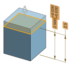
組態應按預期地作用。不過,在尺寸環境對話方塊中並未由橘色虛線輪廓線框出的尺寸是已組態的。無法編輯已組態的草圖尺寸。
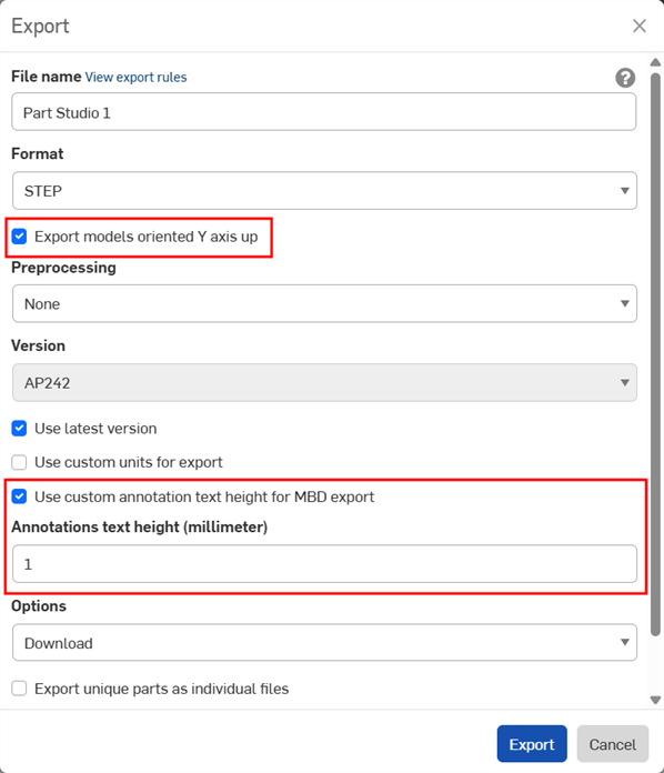
當匯出零件時,可以將 MBD 資料匯出為 STEP 檔案格式。建議使用下列的設定:
不會為封閉的複合零件匯出 MBD 資料。如果文件是開啟的,這個警告會在匯出過程中於「匯出」對話方塊中顯示。不過,如果是從「進階搜尋」文件結果清單中選擇與匯出零件,則不會顯示警告,但仍不會匯出 MBD 資料。
-
啟用以 Y 軸朝上的方位匯出模型核取方塊。
-
取決於您模型的大小,您可能需要啟用 為 MBD 匯出使用自訂的註記文字高度,然後選擇適當的註記文字高度來對應您模型的大小。
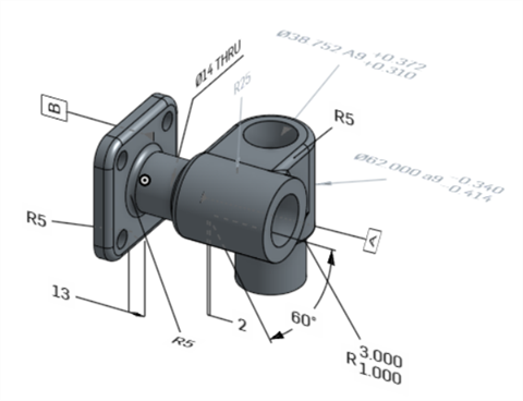
Onshape 中的原始模型
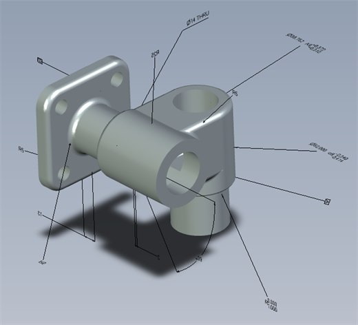
停用「為 MDB 匯出使用自訂註記文字高度」選項的匯出模型
啟用「為 MDB 匯出使用自訂註記文字高度」選項,並設定為 10 mm 的匯出模型。
當匯出時,有多個公差框架的幾何公差會將其上方文字 與上方框架結合,下方文字則與底部框架結合。
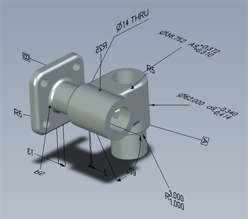
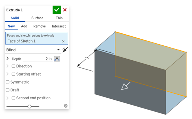
下方提供操作特徵與尺寸公差時的 MBD 範例:
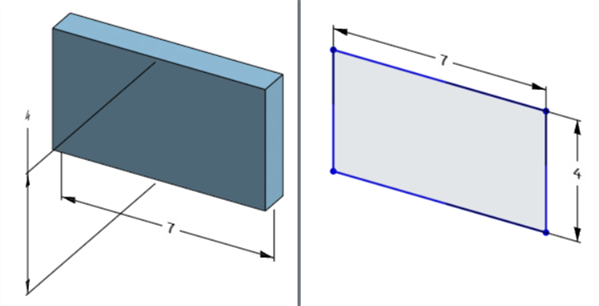
深度尺寸:
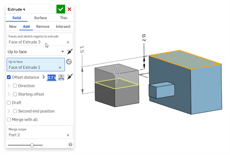
偏移距離尺寸 (與一複合零件):
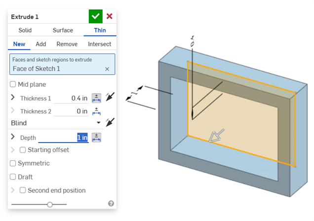
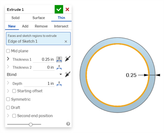
薄件擠出 (厚度 1 與深度尺寸):
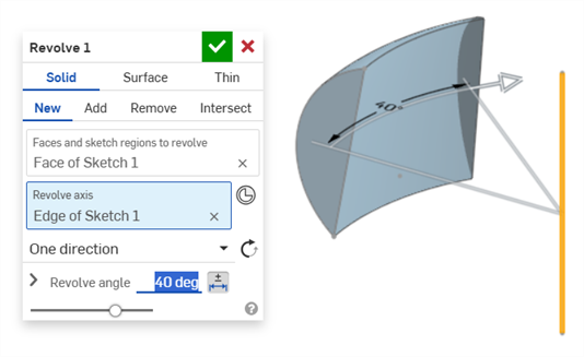
旋轉 (旋轉角度尺寸):
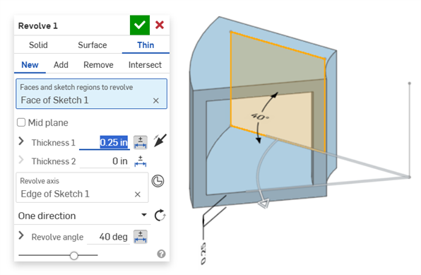
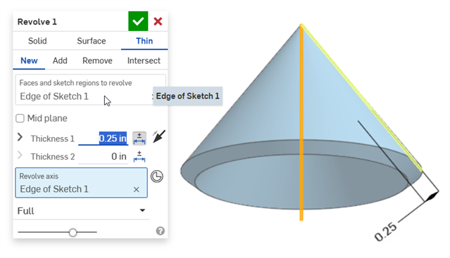
旋轉 (厚度 1 與旋轉角度尺寸):
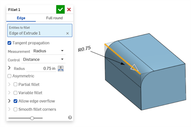
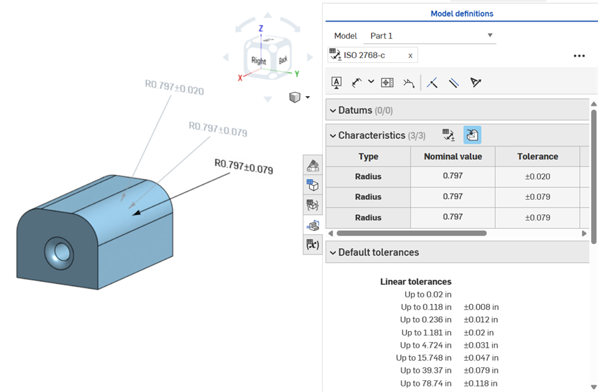
倒角的定義是面與邊線間的距離到角度或距離到距離。倒角寬度尺寸是指從邊線到虛擬交角間的距離。會將虛擬交角的顯示加入到標註尺寸的邊線上,包括一條虛線曲線。
-
當使用相切測量時,不會停用公差,因為它們在某些情況下可以作用,特別是在考慮特定公差的情況下。
-
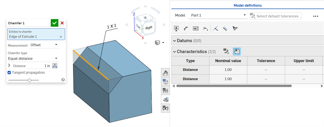
在使用了兩個倒角測量的情況下 (「兩個距離」或「距離和角度」),使用者不需要為兩者都建立公差。如果需要,可以僅將公差加入至一個參數中。
即使在對話方塊中只有一個距離公差選項,「同等距離」「導角類型」顯示 2 個反映在表格中的「距離」公差值:
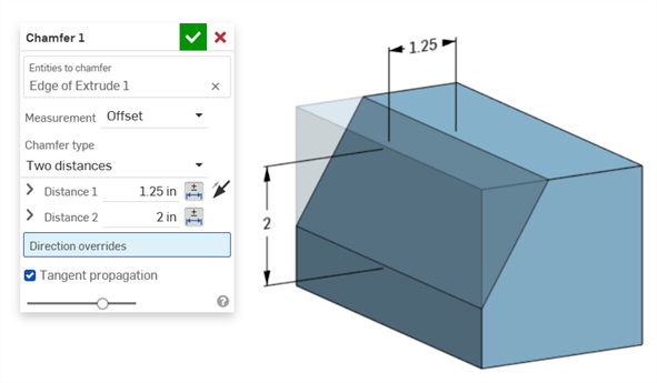
「兩個距離」範例:
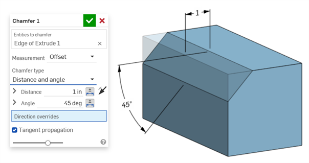
「距離和角度」範例:
對於倒角導致距離變化的情況 (例如,如果倒角是套用在與另一個圓柱垂直連接的圓柱面上),請嘗試為「測量」選擇相切來使得沿邊線的距離一致:
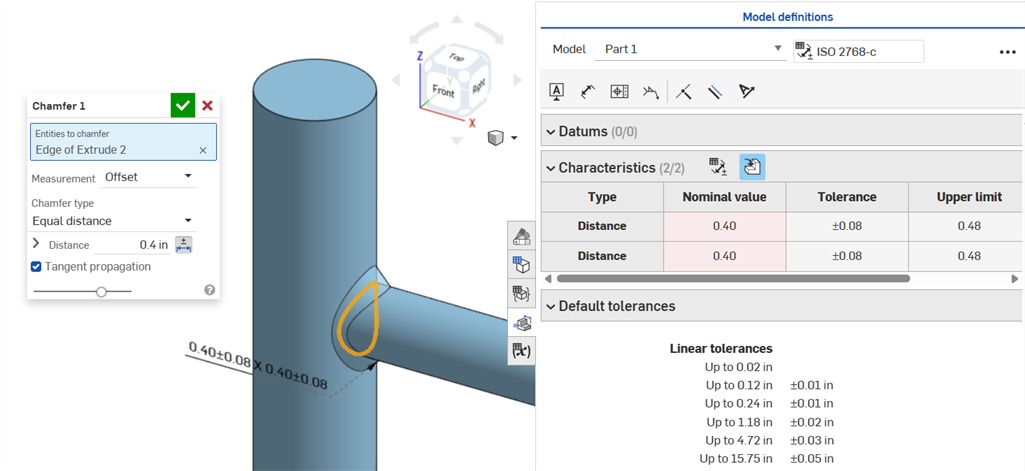
使用「偏移」測量的非一致倒角顯示標稱值的錯誤。
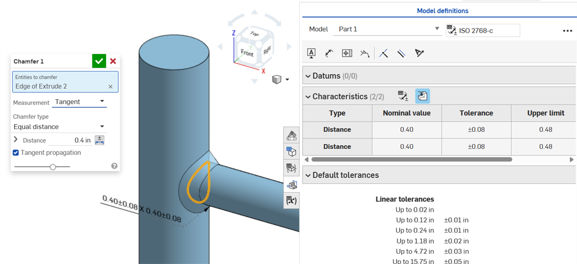
使用「相切」測量的一致倒角產生沒有錯誤的標稱值。
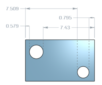
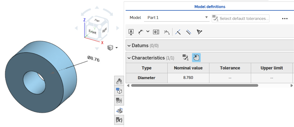
如果將公差放置在鑽孔特徵上,可將其顯示在檢查表格中。
注意事項:
-
鑽孔尺寸僅會以列的形式顯示在檢查表格中。在圖形區域中不會放置尺寸。這樣做是為了避免在圖形區域中過於擁擠。
-
要在檢查表格中顯示鑽孔尺寸之前,必須先將另一個標註 (例如,基準) 放置在零件上。
-
每個鑽孔特徵僅會顯示一組尺寸 (「直徑」、「距離」、和/或「角度」)。不會分開標註同一特徵中的複製排列鑽孔或額外鑽孔的尺寸。
-
目前並不支援自訂的「頂錐角」尺寸,且不會在檢查表格中建立一個列。
-
交叉強調顯示的作用如下:
-
不會交叉強調顯示距離 (深度),因為在鑽孔的兩端沒有面,且目前在 MBD 中不支援邊線。
-
直徑、距離 (埋頭孔深度)、與角度 (沉頭孔角度) 會交叉強調顯示單一面。
-
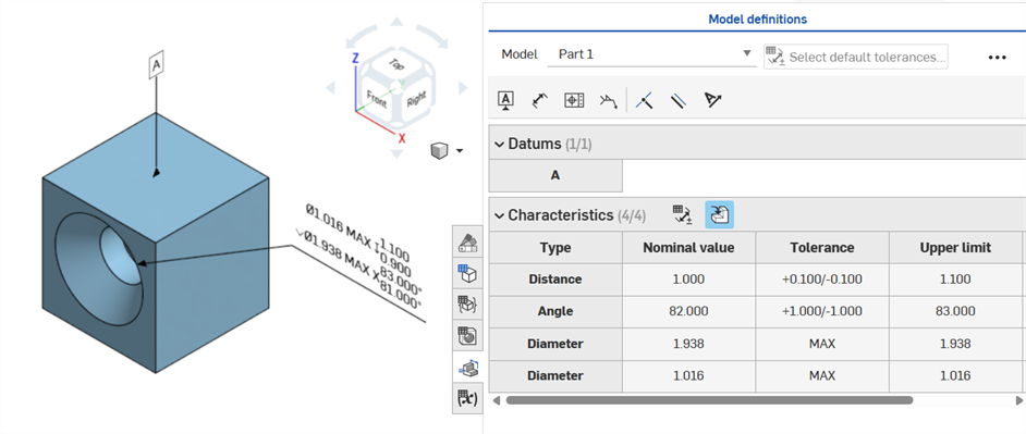
在將基準加入至零件的一個面後,鑽孔尺寸顯示在檢查表格中。
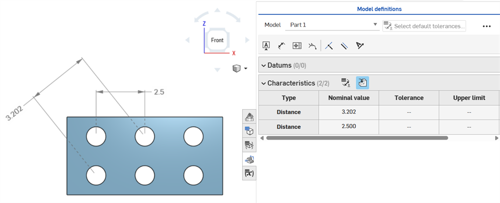
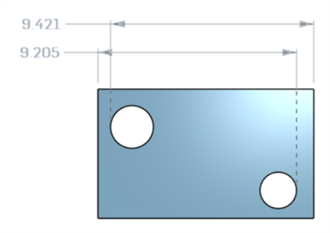
使用尺寸 (![]() ) 工具測量中心圓之間的軸距離尺寸:
) 工具測量中心圓之間的軸距離尺寸:
使用最小尺寸工具 (![]() ) 測量兩個圓柱面間的最小水平、對角、與垂直尺寸:
) 測量兩個圓柱面間的最小水平、對角、與垂直尺寸:
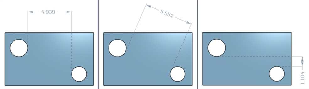
圓柱與邊線間的最小尺寸:
在建立零件之後,最小對角線尺寸被加入至草圖中 (左圖),並顯示在「特性」表格內 (右圖):
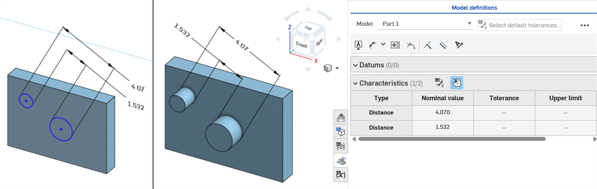
目前無法在草圖中建立水平與垂直最小尺寸。
使用最大尺寸 工具 (![]() ) 測量兩個圓柱面間的最小水平、對角、與垂直尺寸:
) 測量兩個圓柱面間的最小水平、對角、與垂直尺寸:
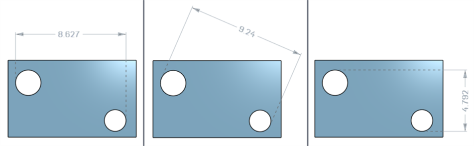
圓柱與邊線間的最大尺寸:
在溝槽中弧面間最大水平、對角、與垂直尺寸:
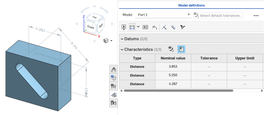
在建立零件之後,最大對角線尺寸被加入至草圖中 (左圖),並顯示在「特性」表格內 (右圖):
目前無法在草圖中建立水平與垂直最大尺寸。
厚度會在檢查表格中以距離列來顯示。
薄件擠出 (厚度 1 尺寸):
薄件旋轉 (厚度 1 尺寸):
啟用了公差的草圖中心線尺寸:
若以中心線為軸來繞著旋轉草圖幾何,在開啟檢查表格時,會將中心線顯示為直徑尺寸:
隨著加入註記,變更模型,以及套用特徵的更新,Onshape 會自動嘗試驗證相關的 MBD 資料。
驗證是以每個零件為基礎進行的;因此,註記必須參考來自同一零件或複合零件的幾何。
當某個特性是無效的時,註記與在檢查表格中的相對應特性都會是紅色的。
無效的特性分為兩類:遺失參考與值不相符。
遺失的參考會發生在用來定義特性的幾何已不再存在,或有所改變而導致關聯斷開。這可能是由於刪除了特徵、置換了面,或另一個拓撲的改變。
值的不相符會發生在當參考幾何的值與定義的公差不再相符時。例如,當鑽孔直徑增加超出指定的限制時會發生這種狀況。
評估潛在原因來解決無效的特性。
當使用「比較」時,選擇面來檢視其相關的註記、公差與特性。
修改「特徵」清單與 MBD 註記來驗證與解決錯誤。
MBD 錯誤不會在檢查表格中建立註記或列的條目,除非對模型所做調整會使得現有的註記列條目無效。
會以紅色顯示錯誤,類似於其他的 Onshape 錯誤:
當從實體擠出或擠入實體時發生錯誤。註記不會在檢查表格中產生列條目。
如果修改了幾何而使得特定的註記無效,在圖形區域中的相對應註記會是紅色的,並在檢查表格中以紅色強調顯示,表示有錯誤。例如,方塊的頂面移動了 .5 in.,導致測量值 (3.5 in.) 與指定的值 (3.0 in.) 不同:
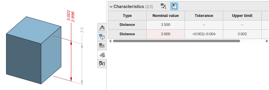
錯誤範例
-
這個註記遺失了參考 - 當遺失參考時發生。例如,零件 A 是擠出至零件 B 的面上,然後將公差加入至零件 A 擠出的「偏移距離」上。
-
兩個面都必須來自相同的零件 - 模型定義僅在各零件的基礎上有效。例如,您無法標註從零件 A 中一個面到零件 B 中一個面的距離。
-
MBD 註記必須永遠與面相關。目前無法參考邊線和頂點。
-
模型定義僅在各零件基礎上有效。對複合零件也是有效的。例如,您可以標註零件 A 上 2 個面間的距離,或是標註零件 B 上 2 個面間的距離,但無法標註零件 A 上的一個面與零件 B 上一個面的距離。為此,請先從零件 A 與零件 B 來建立一個複合零件 C。然後您可以標註這 2 個面之間的距離。
-
將游標移至檢查表格中的「類型」列上暫留以在圖形區域中交叉強調顯示尺寸。
-
當修改零件的幾何時,相關的模型定義會以橘色強調顯示:
-
如果是藉由「衍生」特徵來導出零件或 Part Studio,所有的模型定義都是唯讀的且無法編輯。您仍可以移動註記,且如果修改了衍生的幾何,仍會更新衍生的尺寸;不過,僅能在來源 Part Studio 中調整基礎的模型定義,然後在「衍生」特徵中更新。詳細資訊請參考衍生。
-
可以對公差草圖尺寸、特徵尺寸、鑽孔標註、與檢查表格註記 (尺寸、基準、幾何公差) 在圖形區域中加入評論與標記。詳細資訊請參考在 MBD 註記上加入評論。