![]()
![]()
![]()
编辑现有曲线或通过选择草图图元或曲线来创建新曲线,以应用简化的近似值、提升度数、重新定位控制曲线顶点和/或平面化为任何 2D 平面。
编辑曲线允许您在编辑曲线的同时保持其与依赖它的任何下游特征的关联。这有助于校正建模链上游由于不良曲线而导致的任何曲面。例如,如果放样导致曲面损坏,则编辑用作放样基础的原始曲线会得到更好的曲面。
使用“编辑曲线”特征可以:
-
改进导入的曲线几何形状,使其平滑、平整、重建、重新参数化和重新近似。
-
通过控制点编辑现有曲线的形状。
-
参照其他几何图元定位曲线的控制点。例如,如果您对横杆有几种备用尺寸的配置,并希望不同零件的曲线更新其与横杆的对齐方式。
-
提高曲线的度数以匹配所需的度数,改善连接性或更精细地控制曲线的形状。
-
校正曲线中不必要的扭转/扭曲。曲线及其控制点移至选定平面或嵌合连接器以拉直曲线(平面化)。
曲线通常用于为复杂 3D 几何图元提供基础,无论是用作复杂放样和边界曲面的引导曲线,还是用于扫描的路径。有时,可能需要调整这些曲线以匹配所需的设计意图。在这些情况下,Onshape 的“编辑曲线”特征允许修改曲线,同时保持与依赖曲线的下游特征的任何关联。例如,曲线可能有不必要的扭曲,从而影响放样特征的形状。编辑曲线以平滑扭曲会使放样更平滑。
“编辑曲线”特征提供多个选项,用于重建曲线、重塑曲线以及处理来自各种原生或导入源的曲线。
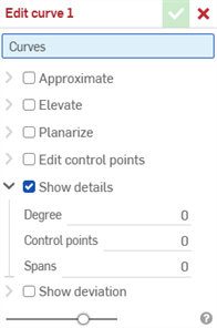
编辑曲线特征还允许您显示或隐藏度数、控制点数量和跨度数的只读曲线值。
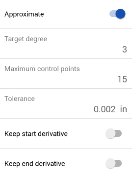
选中“近似”以重新近似曲线。这会将曲线重建为新的数学规范。设置“目标度数”、“最大控制点数”和“公差”。选中“保持起始导数”和“保留末端导数”以保持曲线两端的切线。
选中“提升”可为曲线提供新的目标角度。此选项将曲线提升到这个新的更高程度,从而增加了控制点的数量,从而可以更精细地控制曲线的形状。
选中“Planarize”将曲线的控制点从其当前位置投影到选定的参考平面。有许多选项可以确定 Onshape 项目在哪个平面上投射控制点。“最佳拟合”使用所有控制点位置的平均值将控制点投影到与曲线路径最接近的平面上。选中“锁定端点”可将曲线的端点锁定到其原始位置。YZ、XZ 和 XY 平面将控制点投射到相应的平面上。“自定义”将控制点投影到选定平面或由嵌合连接器提供的平面上。选择嵌合连接器图标以激活对隐式或显式嵌合连接器的选择。
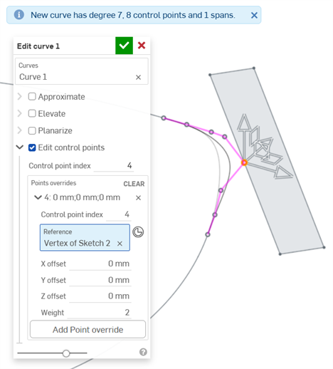
选中“编辑控制点”以修改所选曲线上各个控制点的位置和权重。初始控制点索引为 0,对应于曲线上的第一个控制点。通过输入控制点的索引号或在图形区域中选择相应的控制点来选择其他控制点。选择控制点后,单击“添加点替代”以手动输入偏移量和权重值,或使用图形区域中的三合一操纵器调整位置。默认情况下,这些偏移量是相对于原始控制点位置的,但是当您选择提供“参考”时,您可以将它们从特定点偏移。“权重”决定控制点相对于曲线的权重。权重越大,绘制到控制点的曲线越多。“权重”将曲线上点的影响乘以您输入的值。
对话框操作的顺序从上到下是分层的(从“近似”到“提升”再到“平面化”,最后是“编辑控制点”)。如果您想更改此操作顺序,请创建多个“编辑曲线”特征,这些特征会根据您的要求顺序更改顺序。例如,创建一个“编辑曲线”特征来编辑曲线控制点,再创建一个“编辑曲线”特征以对同一曲线进行平面化。
您可以使用“近似”或“提升”来确保每条曲线上的控制点数目相同,这有助于对齐和平滑放样的曲面。
如果图形区域中至少有一个线性草图图元或曲线可用:
- 单击工具栏中的“编辑曲线”特征 (
 )。
)。
-
在图形区域中选择一个或多个不自相交的线性草图图元和/或曲线。草图图元或曲线必须遵循连续路径,如果选择了多条曲线,则必须对它们进行近似(选中下面的近似),这会生成一条新曲线。
- 选中“近似”可打开重新近似曲线的选项。原始曲线显示为橙色,新的近似曲线以洋红色显示。近似功能试图保持曲线的几何形状,但这并不总是可以保证的。
目标角度 - 输入所选曲线的目标曲线度。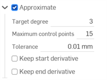
- 最大控制点 - 输入所选曲线允许的最大控制点数。
- 公差 - 所选曲线的公差,以长度为测量值。输入公差值。
- 保持起始导数 - 选中以保持所选曲线起点的切线。
- 保留末端导数 - 选中以保持所选曲线末端的切线。
- 选中“提升”可打开“目标度数”选项。如果需要,为所选曲线输入更高的目标曲线度数。这对于匹配所需角度、改善连接性或更精细地控制曲线的形状很有用。曲线的几何形状得以保留。

- 选中“平面化”可打开沿参考平面拉直曲线的选项。平面化将控制曲线从其当前位置投影到选定的参考平面:

参考平面选项有:
最佳拟合 - 沿与曲线路径最接近的平面投影曲线(使用所有控制点位置的平均值
)。锁定端点 - 检查确保曲线的端点固定在适当位置且不移动。这对于保持附加几何图元的连续性很有用。
YZ 平面 - 沿 YZ 平面(垂直于 X 轴)投影曲线
。XZ 平面 - 沿 XZ 平面(垂直于 Y 轴)投影曲线
。XY 平面 - 沿 XY 平面(垂直 Z 轴)投影曲线
。自定义 - 沿自定义平面或显式或隐式嵌合连接器(垂直于其 Z 轴)的 XY 轴投影曲线。
- 选中“编辑控制点”可打开选项以添加参考,并更改选定曲线上各个控制点的位置和权重:
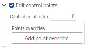
打开“编辑控制点”开关后,三重轴操纵器将在图形区域中可见,其原点位于第一个控制点上(控制点索引 0)。
该“控制点索引”输入框是曲线上某个点的顶级索引/ID。从 0 开始。您可以通过在此字段中输入索引号以数字方式选择每个控制点。当您这样做时,三重轴操纵器会移至图形区域中相应的控制点。
三重轴操纵器可调整:
跨 3 个轴的平移
在 3 个平面上平动。
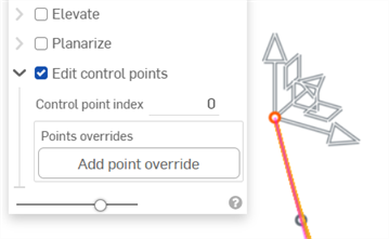
单击“添加点替代”按钮或调整三重轴操纵器会为当前选定点添加一个替代选项:
将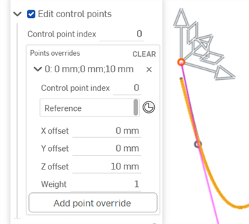
Z 轴操纵器调整 10 mm 可打开当前控制点的选项(上图中的索引 0)。
您可以为曲线上的每个控制点单独添加替代设置。单击“添加点替代”按钮,将自定义的替代设置添加到其他点。每个点只能应用一组替代设置。
通过按下行左侧的三角符号 (
 ) 来展开/折叠每一行/控制点的替代项。每个点的替代项列出索引编号,后面是 X/Y/Z 偏移量。单击每行右侧的 x 以清除该点的替代项。单击表格左上角的“清除”以清除所有行/控制点覆盖的替代设置。
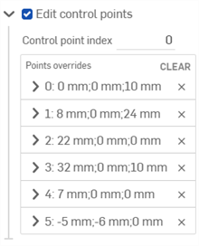
如果需要,编辑以下每个控制点替代选项:
- 控制点索引 - 这是被替代的控制点的索引。选择曲线上某个点的索引/ID。索引从 0 开始。
在此级别切换控制点索引号会将所有当前的点替代设置应用于该控制点。通过这种方式,您可以立即将替代设置从一个控制点转移到另一个控制点。
编辑曲线上每个控制点的以下替代设置:
- 参考 - 默认参考是未更改的控制点位置(三重轴操纵器的起点)。选择顶点、草图点或显式或隐式嵌合连接器,使当前点的X/Y/Z 偏移量相对于该点。
在编辑控制点时,单击“选择嵌合器连接器”图标 (
 ),并在模型中的某个位置上单击,以创建隐式嵌合连接器。这将作为点的参考。
 - X/Y/Z 偏移量 - 显示控制点的当前位置,以及它相对于参考位置的偏移量。如果需要,请在每个输入框中输入数值偏移值。
- 权重 - 确定控制点相对于曲线的权重。较高的权重值会使曲线“拉伸”得更接近控制点。输入权重值,将曲线上点的影响乘以该量。
- 参考 - 默认参考是未更改的控制点位置(三重轴操纵器的起点)。选择顶点、草图点或显式或隐式嵌合连接器,使当前点的X/Y/Z 偏移量相对于该点。
- 添加点替代 - 向表中添加新的点替代,该索引要么是当前选定的索引,要么是数组中位于当前索引之后的第一个未使用的索引(如果已使用当前索引)。
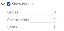
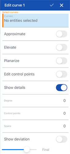
- (可选)默认情况下,“显示详细信息”处于启用状态,并提供度数值、控制点 数量和跨度数量的只读显示。取消选中此选项可隐藏这些详细信息。
- (可选)如果曲线已被重新近似,则可以启用“显示偏差”复选框来查看原始曲线和近似曲线之间的最大偏差。

- 单击复选标记 (
 ) 接受编辑曲线特征。
-
使用“近似”之前(左)和之后的原始曲线(右):

-
从 2 个切向草图图元(左)创建一条新曲线;使用“近似”后,将它们连接成一条曲线(右)。原始草图图元仍然存在,仍然可以用于其他目的。

-
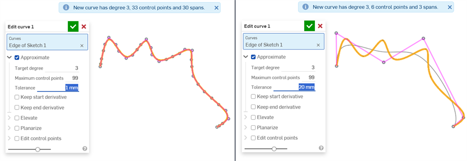
使用“容差”选项平滑曲线:
-
提升以匹配目标度数:
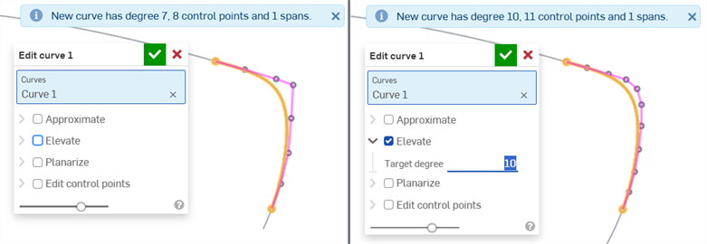
没有任何标高(左)且目标度数提升至 10(右)
-
平坦化以拉直沿平面的曲线:
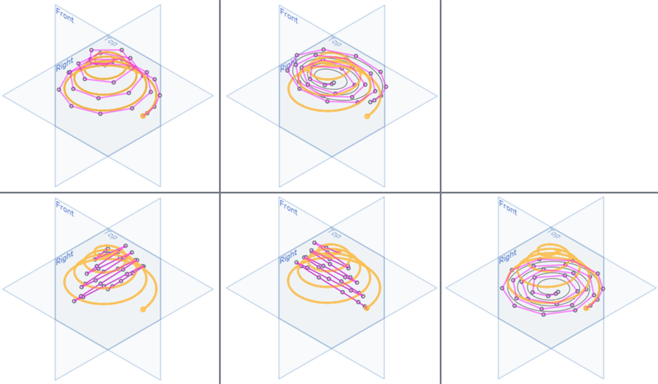
上图:未选中“平面化”(左),最佳拟合(右);底部从左到右:YZ 平面、XZ 平面、XY 平面
-
将螺旋线平面化为螺旋:
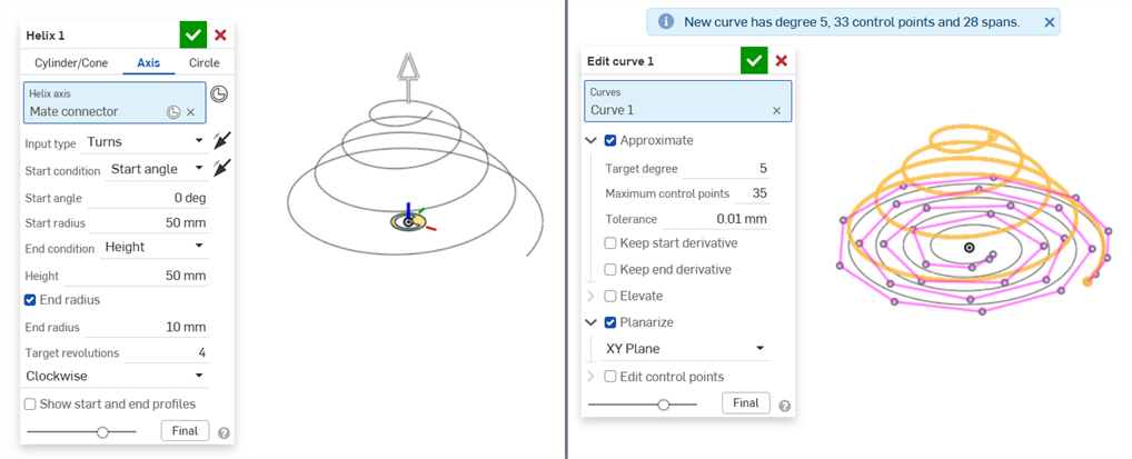
螺旋特征(左),之后使用“编辑曲线” > “平面化”将螺旋线平面化为螺旋(右)
-
使用“自定义”选项进行平面化并选择嵌合连接器作为平面的基础:

平面化未选中(左)和选中(右)。选择“自定义”,并将嵌合配连接器用于自定义平面。
使用自定义嵌合连接器平面进行平面化时的曲线与上述曲线相同,在其他平面的背景下显示:
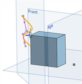
-
沿曲线编辑控制点以微调其形状:
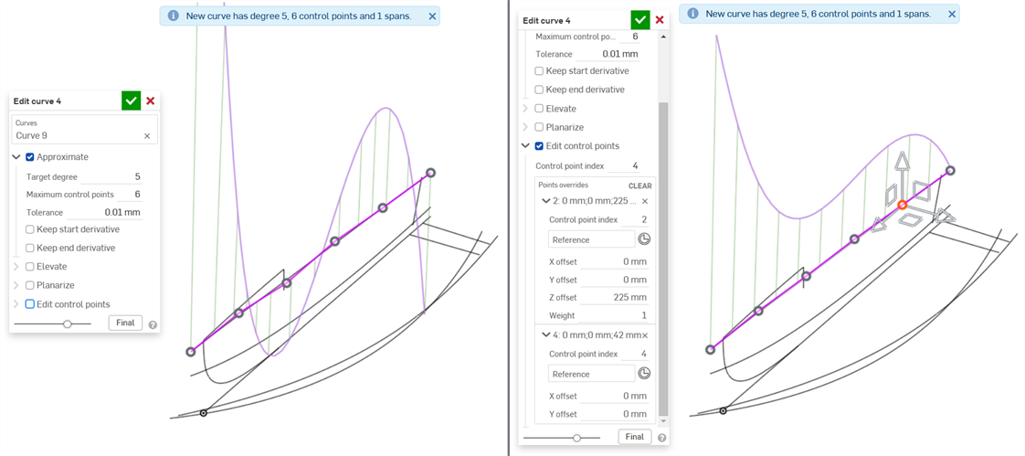
未编辑任何点的原始曲线(左),编辑了点 2 和 4 以创建更平滑的曲线(右)
-
编辑控制点以参考现有几何图元(曲线外部)。使用这种方法,如果参考几何图元发生变化,曲线会遵循该几何图元。例如,如果参考几何图元有几种不同的尺寸并将其设置为配置,则无论选择什么配置,曲线都将始终遵循几何图元。
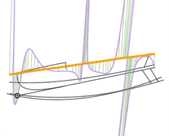
导入 CAD 后,曲线可能不正确。如果您使用错误曲线进行了大量建模工作,直到设计过程的后期才注意到问题,那么这个问题也可能会恶化。
以下是导入 CAD 数据的示例(导入的是用于船的曲线)。使用曲线/曲面分析工具,您可以看到以下曲线存在问题:
当根据这条曲线创建曲面时,来自构造不当的曲线的数据将在设计过程中传递到下游。编辑曲线(下面的第一张图片)会使曲线更平滑(下方第二张图片)。可以在导入过程结束后直接编辑曲线,依赖曲线的所有下游特征都会自动更新:
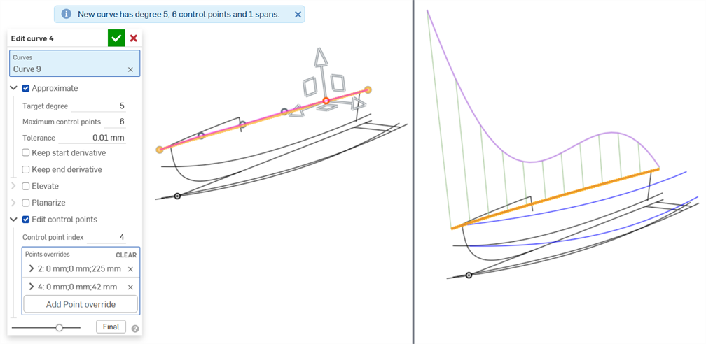
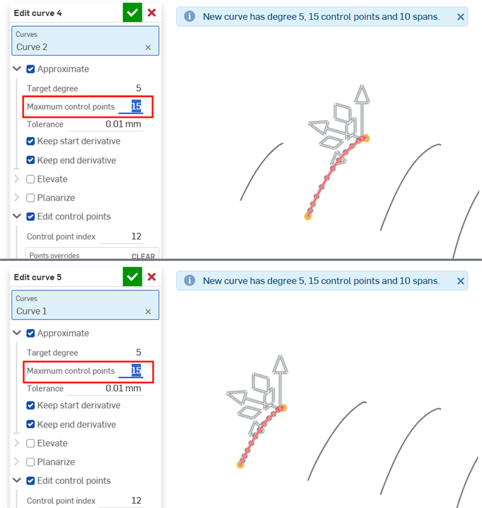
将曲线近似于目标度:5;最大控制点:6,然后编辑控制点以创建平滑曲线。
下图显示了由于使用源自前一曲线的下游特征而生成的边界曲面的质量差异:
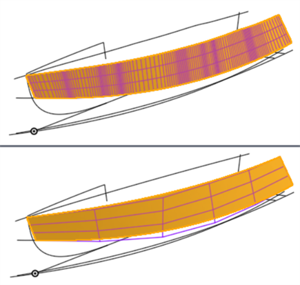
根据曲线创建的边界曲面显示了有问题的曲面(上图)和编辑曲线后质量更好的曲面(下图)。曲线中的控制点越少,曲面越平滑。
-
对曲线应用“编辑曲线”选项时,存在分层顺序或操作(依赖顺序)。首先应用近似,然后应用提升,然后进行平面化,最后应用编辑控制点。如果您希望编辑曲线的控制点,然后将平面化作为下一步,则可以通过创建两个“编辑曲线”特征来实现,一个接一个。在第一个“编辑曲线”特征中,编辑曲线的控制点。然后,在第二个“编辑曲线”特征中,对曲线进行平面化。
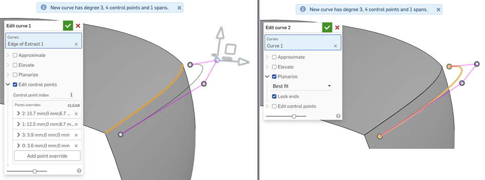
在第一个“编辑曲线”特征(左)中编辑曲线的控制点,并在第二个“编辑曲线”特征(右)中对其进行平面化,以反向在曲线上执行的操作顺序
-
编辑多条曲线作为放样(最终创建曲面)基础时,请确保每条曲线上的控制点数量相等。这样可以确保每条曲线上的点之间有平行度,从而形成清晰的放样效果。
编辑现有曲线或通过选择草图图元或曲线来创建新曲线,以应用简化的近似值、提升度数、重新定位控制曲线顶点和/或平面化为任何 2D 平面。
步骤
如果图形区域中至少有一个线性草图图元或曲线可用:
-
轻按“编辑曲线”工具图标 (
 )。
)。
-
在图形区域中选择一个或多个不自相交的线性草图图元和/或曲线。草图图元或曲线必须遵循连续路径,如果选择了多条曲线,则必须对它们进行近似(选中下面的近似),这会生成一条新曲线。
-
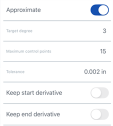
点击“近似”旁边的开关,打开重新近似曲线的选项。原始曲线显示为橙色,新的近似曲线以洋红色显示。近似功能试图保持曲线的几何形状,但这并不总是可以保证的。
-
目标角度 - 输入所选曲线的目标曲线度。
-
最大控制点 - 输入所选曲线允许的最大控制点数。
-
公差 - 所选曲线的公差,以长度为测量值。输入公差值。
-
保持起始导数 - 开启以保持所选曲线起点的切线。
-
保留末端导数 - 开启以保持所选曲线末端的切线。
-
-
点击“提升”旁边的切换开关可打开“目标度数”选项。如果需要,为所选曲线输入更高的目标曲线度数。这对于匹配所需角度、改善连接性或更精细地控制曲线的形状很有用。曲线的几何形状得以保留。
-
轻按“平面化”旁边的开关可打开沿参考平面拉直曲线的选项。平面化将控制曲线从其当前位置投影到选定的参考平面。
参考平面选项包括:
-
最佳拟合 - 沿与曲线路径最接近的平面投影曲线(使用所有控制点位置的平均值)。
-
锁定端点 – 打开以确保曲线的端点固定在适当位置且不移动。这对于保持附加几何图元的连续性很有用。
-
YZ 平面 - 沿 YZ 平面(垂直于 X 轴)投影曲线。
-
XZ 平面 - 沿 XZ 平面(垂直于 Y 轴)投影曲线。
-
XY 平面 - 沿 XY 平面(垂直 Z 轴)投影曲线。
-
自定义 - 沿自定义平面或显式或隐式嵌合连接器(垂直于其 Z 轴)的 XY 轴投影曲线。
-
-
轻按“编辑控制点”可打开选项以添加参考,并更改选定曲线上各个控制点的位置和权重。
打开“编辑控制点”开关后,三重轴操纵器将在图形区域中可见,其原点位于第一个控制点上(控制点索引 0)。
该“控制点索引”输入框是曲线上某个点的顶级索引/ID。从 0 开始。您可以通过在此字段中输入索引号以数字方式选择每个控制点。当您这样做时,三重轴操纵器会移至图形区域中相应的控制点。
您可以为曲线上的每个控制点单独添加覆盖设置。单击“添加点替代”按钮 (位于对话框的“点替代”部分),将自定义的替代设置添加到其他点。每个点只能应用一组替代设置。选择“添加点替代”选项或调整三重轴操纵器会为当前选定的点添加一个替代选项。
通过按下行左侧的三角符号 (
 ) 来展开/折叠每一行/控制点的替代项。每个点的替代项列出索引编号,后面是 X/Y/Z 偏移量。
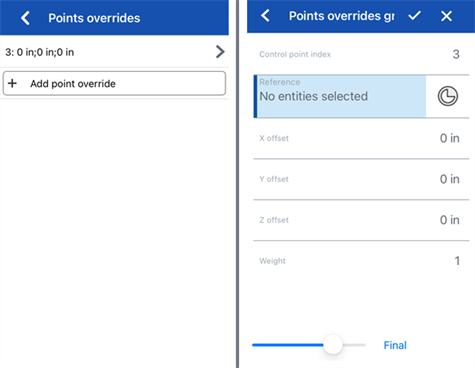
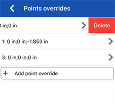
向左滑动并点击“删除”按钮以清除该点的替代项:
如果需要,编辑以下每个控制点替代选项:
-
控制点索引 - 这是被替代的控制点的索引。选择曲线上某个点的索引/ID。索引从 0 开始。
在此级别切换控制点索引号会将所有当前的点替代设置应用于该控制点。这样,您可以立即将替代设置从一个控制点转移到另一个控制点。
编辑曲线上每个控制点的以下替代设置:
-
参考 - 默认参考是未更改的控制点位置(三重轴操纵器的起点)。选择顶点、草图点或显式或隐式嵌合连接器,使当前点的 X/Y/Z 偏移值相对于该点。
要在编辑控制点时创建隐式嵌合连接器,请轻按选择嵌合连接器图标,然后轻按模型中的某个位置来创建嵌合连接器。现在将其用作点参考。
-
X/Y/Z 偏移量 - 显示控制点的当前位置,以及它相对于参考位置的偏移量。如果需要,请在每个输入框中输入数值偏移值。
-
权重 - 确定控制点相对于曲线的权重。较高的权重值会使曲线拉伸得更接近控制点。输入权重值,将曲线上点的影响乘以该量。
-
-
添加点替代 - 向表中添加新的点替代,该索引要么是当前选定的索引,要么是数组中位于当前索引之后的第一个未使用的索引(如果已使用当前索引)。
-
-
(可选)默认情况下,“显示详细信息”处于启用状态,并提供度数值、控制点数量和跨度数量的只读显示。取消选中此选项可隐藏这些详细信息。
-
(可选)如果曲线已被重新近似,则可以切换“显示偏差”选项以查看原始曲线和近似曲线之间的最大偏差。
-
轻按对话框顶部的复选标记接受编辑后的曲线并关闭对话框。
编辑现有曲线或通过选择草图图元或曲线来创建新曲线,以应用简化的近似值、提升度数、重新定位控制曲线顶点和/或平面化为任何 2D 平面。
步骤
如果图形区域中至少有一个线性草图图元或曲线可用:
-
轻按“编辑曲线”工具图标 (
 )。
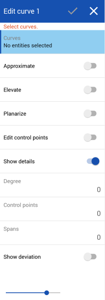
)。
-
在图形区域中选择一个或多个不自相交的线性草图图元和/或曲线。草图图元或曲线必须遵循连续路径,如果选择了多条曲线,则必须对它们进行近似(选中下面的近似),这会生成一条新曲线。
-
点击“近似”旁边的开关,打开重新近似曲线的选项。原始曲线显示为橙色,新的近似曲线以洋红色显示。近似功能试图保持曲线的几何形状,但这并不总是可以保证的。
-
目标角度 - 输入所选曲线的目标曲线度。
-
最大控制点 - 输入所选曲线允许的最大控制点数。
-
公差 - 所选曲线的公差,以长度为测量值。输入公差值。
-
保持起始导数 - 开启以保持所选曲线起点的切线。
-
保留末端导数 - 开启以保持所选曲线末端的切线。
-
-
点击“提升”旁边的切换开关可打开“目标度数”选项。如果需要,为所选曲线输入更高的目标曲线度数。这对于匹配所需角度、改善连接性或更精细地控制曲线的形状很有用。曲线的几何形状得以保留。
-
轻按“平面化”旁边的开关可打开沿参考平面拉直曲线的选项。平面化将控制曲线从其当前位置投影到选定的参考平面。
参考平面选项包括:
-
最佳拟合 - 沿与曲线路径最接近的平面投影曲线(使用所有控制点位置的平均值)。
-
锁定端点 – 打开以确保曲线的端点固定在适当位置且不移动。这对于保持附加几何图元的连续性很有用。
-
YZ 平面 - 沿 YZ 平面(垂直于 X 轴)投影曲线。
-
XZ 平面 - 沿 XZ 平面(垂直于 Y 轴)投影曲线。
-
XY 平面 - 沿 XY 平面(垂直 Z 轴)投影曲线。
-
自定义 - 沿自定义平面或显式或隐式嵌合连接器(垂直于其 Z 轴)的 XY 轴投影曲线。
-
-
轻按“编辑控制点”可打开选项以添加参考,并更改选定曲线上各个控制点的位置和权重。
打开“编辑控制点”开关后,三重轴操纵器将在图形区域中可见,其原点位于第一个控制点上(控制点索引 0)。
该“控制点索引”输入框是曲线上某个点的顶级索引/ID。从 0 开始。您可以通过在此字段中输入索引号以数字方式选择每个控制点。当您这样做时,三重轴操纵器会移至图形区域中相应的控制点。
您可以为曲线上的每个控制点单独添加覆盖设置。单击“添加点替代”按钮 (位于对话框的“点替代”部分),将自定义的替代设置添加到其他点。每个点只能应用一组替代设置。选择“添加点替代”选项或调整三重轴操纵器会为当前选定的点添加一个替代选项。
通过按下行左侧的三角符号 (
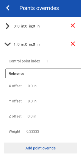
 ) 来展开/折叠每一行/控制点的替代项。每个点的替代项列出索引编号,后面是 X/Y/Z 偏移量。轻按每行右侧的红色 x 可清除该点的替代项。
如果需要,编辑以下每个控制点替代选项:
-
控制点索引 - 这是被替代的控制点的索引。选择曲线上某个点的索引/ID。索引从 0 开始。
在此级别切换控制点索引号会将所有当前的点替代设置应用于该控制点。这样,您可以立即将替代设置从一个控制点转移到另一个控制点。
编辑曲线上每个控制点的以下替代设置:
-
参考 - 默认参考是未更改的控制点位置(三重轴操纵器的起点)。选择顶点、草图点或显式或隐式嵌合连接器,使当前点的 X/Y/Z 偏移值相对于该点。
要在编辑控制点时创建隐式嵌合连接器,请轻按选择嵌合连接器图标,然后轻按模型中的某个位置来创建嵌合连接器。现在将其用作点参考。
-
X/Y/Z 偏移量 - 显示控制点的当前位置,以及它相对于参考位置的偏移量。如果需要,请在每个输入框中输入数值偏移值。
-
权重 - 确定控制点相对于曲线的权重。较高的权重值会使曲线拉伸得更接近控制点。输入权重值,将曲线上点的影响乘以该量。
-
-
添加点替代 - 向表中添加新的点替代,该索引要么是当前选定的索引,要么是数组中位于当前索引之后的第一个未使用的索引(如果已使用当前索引)。
-
-
(可选)默认情况下,“显示详细信息”处于启用状态,并提供度数值、控制点数量和跨度数量的只读显示。取消选中此选项可隐藏这些详细信息。
-
(可选)如果曲线已被重新近似,则可以切换“显示偏差”选项以查看原始曲线和近似曲线之间的最大偏差。
-
轻按对话框顶部的复选标记接受编辑后的曲线并关闭对话框。
除曲面处理工具外,曲线还用于创建曲面的基本构件。
这列出了曲线特征工具的集合。这不是一份详尽的清单。操作曲线时可以使用其他特征工具。
- 草图工具 - 草图工具栏中的工具,例如线、拐角矩形、中心点矩形、中心点圆、三点圆、切线弧、三点弧、三点弧、样条、点和构造,用于在 Part Studio 中创建草图。
-
 螺旋 - 使用圆锥形或圆柱面、嵌合连接器的单轴或 z 轴或圆形边创建螺旋。
 -
 3D 拟合样条-通过一系列顶点创建 3D 拟合样条。创建的曲线列在“曲线”下的零件列表中。
 -
 投影曲线 - 从两个草图的投影创建曲线(“两个草图”选项)或从面上的曲线的投影创造曲线(“曲线到面”选项)。
 -
 桥接曲线 - 创建一条连接任意两个点、顶点或嵌合连接器的曲线。生成的曲线列在特征列表和零件列表中。
 -
 复合曲线 - 将多条边显示为一条曲线。选择多条相邻边、草图图元和其他曲线。选择非连续边可能会导致创建多条曲线。针对每条曲线的选择,必须在其顶点处相遇。(曲线列在零件 > 曲线列表中。)
 -
 相交曲线 - 在两个或多个曲面或面的相交处创建曲线。所选对象必须相交。
 -
 修剪曲线 - 按一定距离修剪或延伸曲线,或修剪或延伸到边界图元。
 -
 等斜线 - 在倾斜的面上创建等斜线。在斜面上创建一条等斜线。等斜线所在面的位置与其参考定义相比具有一定坡度。生成的等斜线将列在特征列表和零件清单中。
 -
 偏移曲线 - 通过偏移周围面的边来创建、延伸和/或分割新曲线。
 -
 等参曲线 - 创建沿 U 或 V 方向的面或曲面延伸的平滑曲线。
 -
 编辑曲线 - 通过选择草图图元或曲线来编辑现有曲线,以应用简化的近似值、提升角度、重新定位控制曲线顶点和/或平面化到任何 2D 平面。
 -
 路线曲线 - 在 3D 空间(布线路径)中创建一条横跨一个或多个平面的多点曲线。这对于为高级曲面创建管道布线、布线和 NURBS 曲线很有用。