 偏移曲线
偏移曲线
![]()
![]()
![]()
通过偏移周围面的边来创建、延伸和/或分割新曲线。
偏移曲线通过偏移周围面的边来创建新曲线,使您无需额外的草图或特征即可创建和控制轮廓。在此示例中,偏移顶面的外边,然后分割。使用其他曲面处理工具提高制造区域以应用纹理。
由于偏移和分割参考取决于剪裁,因此对剪裁轮廓的任何更改也会自动更新分割轮廓。在特征工具栏中单击“偏移曲线”,然后在图形区域中选择一条或多条要偏移的边。选择多条边以创建一条链式曲线或多条不相交的曲线。
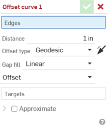
单独的曲线可以在同一个面内重叠而不会出现错误,但无法选择在同一特征内分支的边。输入“偏移距离”和“偏移类型”。“测地线”使用目标面二维空间中的测地线距离来计算偏移量。“欧几里得”使用三维空间中的“欧几里得距离”计算偏移量。如果需要,将偏移曲线反向选定边的另一侧。
从下拉列表中选择填充间隙。“线性”使用线性边填充空白。“圆角”使用与间隙填充两侧的两条曲线相切的圆形边填充间隙。从下拉列表中选择偏移“范围”。选择“偏移并延伸”将曲线的两端延伸到曲面的边。
选中“修剪”以控制曲线的起点和终点。输入值或使用箭头操纵器。“等量修剪”会在修剪的开始和结束处均等地修剪曲线。选择“等量修剪”后,一个操纵器会同时调整两端。如果接受,两个偏移选项都不会分割任何面。
偏移、延伸和分割将曲线的两端延伸到曲面的边,并在偏移处分割曲面。它不会创建单独的曲线。单击“目标”,然后在图形区域中选择一个或多个目标面,将曲线限制在这些面上。如果接受,偏移量仅出现在这些面上。不选择任何面与选择模型中的所有面相同。
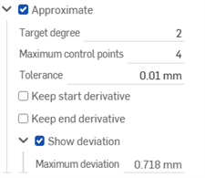
选中“近似”可简化复杂曲线。Onshape 将曲线重建为新的数学规范。设置参数以控制 OnShape 如何简化曲线。设置“目标度数”、“最大控制点数”和“容差”。选中“保持起始导数”和“保留末端导数”以保持曲线两端的切线。选中“显示偏差”以查看原始曲线和近似曲线之间的最大偏差。近似值选项以黄色显示原始曲线,以洋红色显示新的近似曲线。
- 在特征工具栏上选择“偏移曲线”图标 (
 )。
)。
- 在图形区域中选择一条或多条要偏移的边。
- 以数字方式输入与原始边的偏移距离。
-
从下拉菜单中选择“偏移类型”:
-
测地线 - 使用测地线距离计算偏移量。距离是在目标面的 2D 空间中计算的。

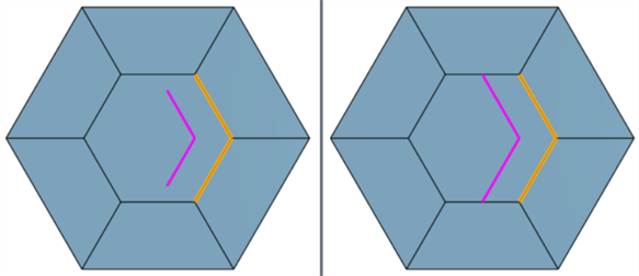
黄色是选取的边,紫红色则是偏移的边(左图)。测量显示从边到偏移曲线如何计算测地线距离(右图)。
-
欧几里得 - 使用欧几里得距离计算偏移量。距离是在 3D 空间中计算的。

黄色是选取的边,紫红色则是偏移的边(左图)。测量显示从边到偏移曲线如何计算欧几里得距离(右图)。
-
-
或者,单击反转箭头将偏移曲线反转到所选边的另一侧。
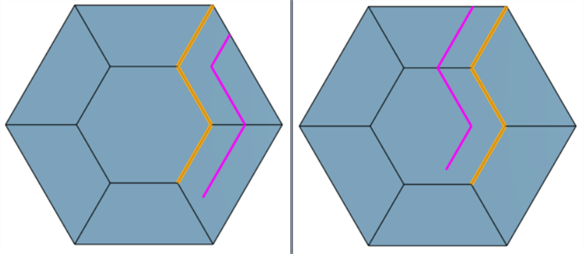
默认(左图)和反转的偏移曲线(右)
-
从下拉菜单中选择“间隙填充”:
-
线性 - 用线性边填充间隙。
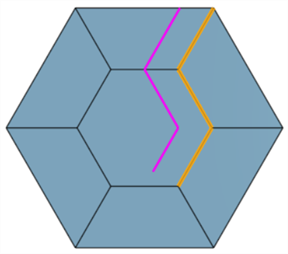
-
圆形 - 使用与间隙填充两侧的两条曲线相切的圆边填充间隙。
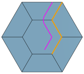
-
-
从下拉菜单中选择以下“范围”选项之一:
-
偏移 - 曲线从边偏移。
-
偏移和延伸 - 将曲线的两端延伸到面的边。
处理后:无(左图)和延伸(右图)
-
如果选择了“偏移和延伸”,则“修剪”控制选项可用。选中 “修剪”并以数字形式输入“开始修剪”和“结束修剪”值,或使用起点和终点修剪箭头操纵器将修剪的起点和终点直观地放置在图形区域中。
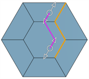
-
选中“等量修剪”,在修剪的开始和结束处均等地修剪曲线。选中“等量修剪”后,一个操纵器会对起始和结束修剪进行同等调整。
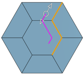
-
-
偏移、延伸和分割 - 偏移曲线的两端并将其延伸到面的边,同时分割面以创建新的面。使用此选项,不会创建新曲线。
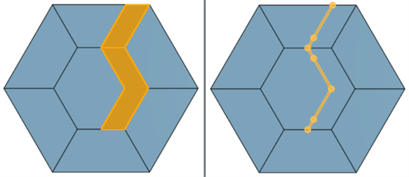
范围:偏移、延伸和分割(左图)以及偏移和延伸(显示曲线;右图)
-
- 单击“目标”输入框,然后在图形区域中选择一个或多个目标面,将曲线约束在这些面上。如果未选择任何面,则与选择的所有面效果相同。

以顶面为目标(左图)、以中间面为目标(中间图),未设定目标(右图)。
-
可以重新近似复杂曲线以创建更简单的曲线。选中“近似”可打开选项以重新近似曲线。原始曲线显示为橙色,新的近似曲线显示为洋红色。
- 目标角度 - 输入所选曲线的目标曲线度。
- 最大控制点 - 输入所选曲线允许的最大控制点数。
- 公差 - 所选曲线的公差,以长度为测量值。输入公差值。
- 保持起始导数 - 选中以保持所选曲线起点的切线。
- 保留末端导数 - 选中以保持所选曲线末端的切线。
- 显示偏差 - 检查以查看原始曲线和近似曲线之间的最大偏差。
- 单击复选标记以接受新的偏移曲线。
-
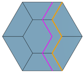
可以选择多条边来创建链状曲线:
-
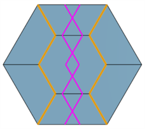
偏移曲线可以在相同的面内相互交叉:
-
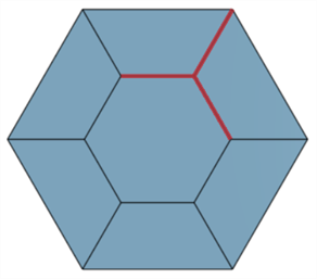
选择分支的边会导致错误。无法从这些分支边创建偏移曲线:
除曲面处理工具外,曲线还用于创建曲面的基本构件。
这列出了曲线特征工具的集合。这不是一份详尽的清单。操作曲线时可以使用其他特征工具。
- 草图工具 - 草图工具栏中的工具,例如线、拐角矩形、中心点矩形、中心点圆、三点圆、切线弧、三点弧、三点弧、样条、点和构造,用于在 Part Studio 中创建草图。
-
 螺旋 - 使用圆锥形或圆柱面、嵌合连接器的单轴或 z 轴或圆形边创建螺旋。
 -
 3D 拟合样条-通过一系列顶点创建 3D 拟合样条。创建的曲线列在“曲线”下的零件列表中。
 -
 投影曲线 - 从两个草图的投影创建曲线(“两个草图”选项)或从面上的曲线的投影创造曲线(“曲线到面”选项)。
 -
 桥接曲线 - 创建一条连接任意两个点、顶点或嵌合连接器的曲线。生成的曲线列在特征列表和零件列表中。
 -
 复合曲线 - 将多条边显示为一条曲线。选择多条相邻边、草图图元和其他曲线。选择非连续边可能会导致创建多条曲线。针对每条曲线的选择,必须在其顶点处相遇。(曲线列在零件 > 曲线列表中。)
 -
 相交曲线 - 在两个或多个曲面或面的相交处创建曲线。所选对象必须相交。
 -
 修剪曲线 - 按一定距离修剪或延伸曲线,或修剪或延伸到边界图元。
 -
 等斜线 - 在倾斜的面上创建等斜线。在斜面上创建一条等斜线。等斜线所在面的位置与其参考定义相比具有一定坡度。生成的等斜线将列在特征列表和零件清单中。
 -
 偏移曲线 - 通过偏移周围面的边来创建、延伸和/或分割新曲线。
 -
 等参曲线 - 创建沿 U 或 V 方向的面或曲面延伸的平滑曲线。
 -
 编辑曲线 - 通过选择草图图元或曲线来编辑现有曲线,以应用简化的近似值、提升角度、重新定位控制曲线顶点和/或平面化到任何 2D 平面。
 -
 路线曲线 - 在 3D 空间(布线路径)中创建一条横跨一个或多个平面的多点曲线。这对于为高级曲面创建管道布线、布线和 NURBS 曲线很有用。
iOS 和 Android 对“偏移曲线”特征的支持仅限于显示和编辑现有曲线。偏移曲线只能在桌面(浏览器)平台上创建。它们无法在 iOS 或 Android 平台上创建。