 태그
태그
![]()
프레임 또는 파트에 사용할 스케치 프로파일 요소에 태그를 지정하여 금속 판재 양식에서 추가하거나 제거합니다. 형상을 선택하고, 방향을 정의하고, 속성을 추가합니다.
Onshape는 프레임 피처에 직접 내장된 표준 구조 프로파일 라이브러리를 제공합니다. 하지만 프레임 프로파일의 사용자 지정 라이브러리를 만들어야 하는 경우가 있을 수 있습니다. 프레임 피처와 함께 사용할 사용자 지정 프로파일을 만들고 공유하는 것은 매우 쉽습니다. 이 비디오에서는 스케치 라이브러리를 정의하고, 다양한 크기 옵션에 맞게 프로파일을 구성하고, 절단 목록 테이블이 세그먼트와 세그먼트 속성으로 채워지도록 프로파일에 태그를 지정하여 이 작업을 수행하는 방법을 살펴봅니다.
새 프로파일 라이브러리를 만들려면 새 Onshape 통합문서를 만드십시오. 하나 이상의 라이브러리 통합문서에서 프로파일을 구성합니다. 라이브러리 통합문서를 Company 또는 엔터프라이즈의 루트에 있는 폴더에 배치합니다. 이렇게 하면 프로파일을 사용해야 하는 다른 사용자와 쉽게 공유할 수 있습니다.
Part Studio에서 프로파일 스케치를 작성합니다. 각 프로파일 스케치에 대해 고유한 Part Studio를 작성합니다. 스케치할 때 프로파일을 어떻게 정렬할지 고려하십시오. 필요한 경우 추가 정렬 점으로 사용할 스케치 점을 추가합니다. 치수와 관계식으로 스케치를 정의합니다. 다양한 프로파일 크기 옵션에 맞게 구성하려는 스케치 치수를 정의할 때 변수를 사용합니다. 변수를 사용하면 프로파일의 중요한 값을 쉽게 식별할 수 있습니다. 프로파일을 설명하기 위해 Part Studio와 스케치의 이름을 바꿉니다. 고유한 이름을 사용하면 사용자가 프로필의 의도를 더 쉽게 이해할 수 있습니다. 프로파일을 선택하면 대화상자의 맨 위에 Part Studio 이름이 표시되고 아래에 스케치 이름이 표시됩니다.
동일한 형상의 여러 크기로 프로파일을 사용할 수 있는 경우, 스케치 치수 또는 변수 값을 구성합니다. 각 크기에 대한 구성 입력을 사용하여 구성 테이블을 작성합니다. 그런 다음, 치수 또는 변수(사용되는 경우)를 구성합니다. 스케치를 편집하고, 구성을 실행할 각 치수를 마우스 오른쪽 버튼으로 클릭한 후 '치수 구성'을 선택합니다. 변수를 사용하여 스케치를 정의하는 경우, 변수를 편집하고 값을 마우스 오른쪽 버튼으로 클릭한 후 '구성'을 선택합니다. 구성 테이블의 값을 편집합니다.
다음으로 새 태그 피처를 시작하고 드롭다운에서 프레임을 선택합니다. 태그 기능은 프로파일에 속성을 추가하므로 프레임 피처에서 사용할 때 절단 목록 테이블에 표준 및 설명 같은 열 헤더가 표시되고 해당 속성의 값이 채워집니다.
스케치 프로파일을 선택합니다. 그래픽 영역이나 피처 리스트에서 선택할 수 있습니다. 추가 정렬 점이 필요한 경우 선택 필드를 확장하고 스케치에서 정렬 점으로 사용할 점을 선택합니다. 그런 다음 표준 및 설명에 숫자 또는 텍스트 문자열을 입력합니다. 이러한 필드를 비워 두면 프로파일을 사용할 때 해당 열이 절단 목록에 추가되지 않습니다. 구조에서 사용된 다른 프로파일에 해당 열 헤더가 정의된 경우 해당 셀에 “설정되지 않음”이 표시됩니다. 표준 입력과 설명 입력을 모두 구성할 수 있습니다. 태그 프로필 대화상자의 필드를 마우스 오른쪽 버튼으로 클릭하고 구성을 선택합니다. 그런 다음 구성 테이블의 셀을 편집합니다.
프로파일에 추가 속성을 제공하려면 열 추가를 클릭하고 헤더 및 값 정보를 입력합니다. 필요에 따라 반복하여 절단 목록 테이블에 열을 더 추가합니다. 완료되면 체크마크를 클릭합니다. 이러한 속성은 구성할 수 없습니다. 대화상자의 삭제 버튼(X)을 클릭하여 열을 모두 제거합니다.
체크 표시를 클릭하여 태그 피처를 적용합니다. 이제 이 프로파일을 이 통합문서에 포함된 구조와 함께 사용할 수 있습니다. 다른 Part Studio에서 새 프레임 피처를 시작하고 대화상자에서 스케치 프로파일 선택을 클릭합니다. 현재 통합문서에서 프로파일을 선택합니다. 구성을 조정하고 생성을 클릭하여 구성된 값을 적용합니다. 그런 다음 스케치 프로파일을 선택합니다.
사용자 정의 프로파일 라이브러리를 만들 때는 프로파일을 사용하는 설계와 다른 통합문서에 프로파일을 보관하십시오. 이 경우 완료 후 프로파일이 들어 있는 통합문서의 버전을 지정해야 합니다. 그때부터 링크된 통합문서를 사용하여 프로파일을 참조할 수 있습니다. 이 예에서는 다른 통합문서에 사용자 지정 프로파일이 포함되어 있습니다. 기타 통합문서를 클릭하고 해당 통합문서로 이동한 다음 스케치 프로파일을 선택합니다.
다른 사용자가 사용자 지정 프로필에 액세스할 수 있도록 하려면 프로파일이 포함된 통합문서 또는 폴더를 공유해야 합니다. 프레임 기능에서 사용자 지정 프로파일을 참조해야 하는 사용자에게는 보기 및 링크 권한만 있으면 됩니다. 사용자 지정 프로파일 관리를 돕는 사용자에게는 편집 및 연결 권한이 필요합니다. 팀을 사용하여 공유하는 것은 적합한 사람에게 액세스 권한을 부여하고 액세스를 더 쉽게 관리할 수 있는 좋은 방법입니다. 조직에서 인사 변경이 발생하면 개별 공유보다 팀에서 사용자를 추가하거나 제거하는 것이 더 쉽습니다.
생성하거나 수정한 프로파일에 태그를 지정하고 컷 목록 테이블의 정보를 추가 열로 사용하려면:
- Click the Tag icon (
 ) to open the Tag dialog:
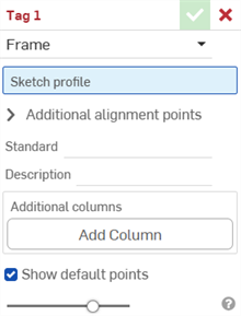
-
태그용으로 프레임을 선택합니다.
- 스케치 프로파일 필드의 피처 리스트에서 프로파일의 스케치로 사용될 스케치를 선택합니다.
-
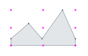
기본적으로 대화상자에서는 기본점 표시가 활성화되어 있습니다. 그러면 스케치 프로파일에 자홍색 9점 정렬 모눈이 중첩되어 배치됩니다. 정렬점을 숨기려면 이 옵션을 선택 취소합니다.
-
추가 정렬 점 필드에서 정렬에 사용할 스케치의 다른 점을 선택합니다.
- 표준 필드에서 절단 목록 테이블의 표준 열에 표시할 값을 입력합니다.
- 설명 필드에서 절단 목록 테이블의 설명 열에 표시할 설명을 입력합니다.
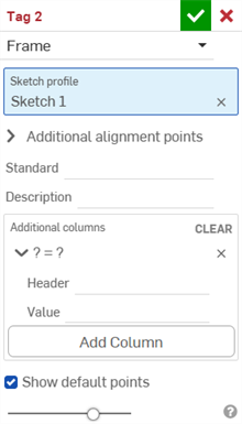
- 프로파일의 정보에 대한 추가 열을 제공하려면 열 추가를 클릭합니다.
-
헤더 필드에서 추가 프로파일의 절단 목록 테이블에 나타날 새 열 헤더의 이름과 값을 입력합니다.
-
열 추가를 클릭하여 또 다른 열/값 쌍을 절단 목록 테이블에 추가합니다.
-
체크마크(
 )를 클릭합니다.
모범 사례는 프로파일에 태그를 지정하고, 버전을 생성하여, 프레임에서 프로파일 버전을 참조하는 것입니다.

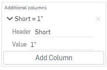
설명 열의 새 값과 해당 값을 포함한 추가 열 “Short”(위)를 주목하십시오.
프레임 피처에 사용된 후에 절단 목록 테이블에 프로파일의 새로운 정보가 나타나고, 뒤이어 테이블을 생성하기 위한 절단 목록 테이블 피처가 나옵니다. 창의 오른쪽에 있는 ![]() 을 클릭하여 테이블 패널을 엽니다.
을 클릭하여 테이블 패널을 엽니다.
양식 태그는 금속 판재 모델에 재질을 추가하거나 제거하는 양식 피처로 사용할 비-금속 판재 파트를 지정합니다.
파트에 태그를 지정하려면,
- 태그 아이콘(
 )을 클릭하여 태그 대화상자를 엽니다.
-
태그에 사용할 양식을 선택합니다.
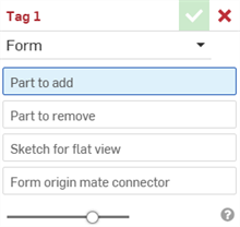
- 추가할 파트 필드에서 파트 목록 또는 그래픽 영역에서 금속 판재에 추가할 파트를 선택합니다.
- 제거할 파트 필드에서 파트 목록 또는 그래픽 영역에서 금속 판재에서 뺄 파트를 선택합니다.
- 평면도용 스케치를 선택합니다. 이것은 금속 판재 모델의 평면도에 사용되는 스케치입니다.
- 양식 원점 메이트 커넥터를 선택합니다. 이에 따라 금속 판재 모델에서 양식이 형성되는 방향이 결정됩니다. 그래픽 영역 모델 위로 마우스를 가져가 암시적 또는 명시적 메이트 커넥터를 선택합니다. 아무 것도 선택하지 않은 경우 피처는 Part Studio의 원점에 하나를 작성합니다.
- 체크마크(
 )를 클릭합니다.
금속 판재 파트를 선택하지 마십시오. 표준 형상 파트를 선택하십시오.
금속 판재 파트를 선택하지 마십시오. 표준 형상 파트를 선택하십시오.
Part Studio당 하나의 유효한 양식 태그 피처만 사용할 수 있습니다. Part Studio당 양식 1개를 생성하십시오.
-
 프레임 - 프로파일을 공유하는 스윕된 바디 집합을 생성하여 끝단을 정렬합니다.
 -
 프레임 잘라내기 - 정렬된 그룹에 따라 세그먼트를 잘라냅니다.
 -
 거싯 - 인접한 프레임 세그먼트 사이에 거싯을 생성합니다.
 -
 엔드 캡 - 프레임 세그먼트에 대해 하나 이상의 엔드 캡을 생성합니다.
 -
 절단 목록 - 특성과 함께 프레임에서 모든 세그먼트의 절단 목록을 생성합니다. 이 작업은 해당 모음에 대해 개방된 합성 파트도 생성합니다.
 -
 태그 - 프레임 또는 파트에 사용할 스케치 프로파일 요소에 태그를 지정하여 금속 판재 양식에서 추가하거나 제거합니다. 형상을 선택하고, 방향을 정의하고, 속성을 추가합니다.