 タグ
タグ
![]()
フレームやパーツで使用するスケッチの輪郭エンティティにタグを付けて、シートメタルフォームに追加したり、シートメタルフォームから削除したりできます。ジオメトリを選択し、方向を定義して、プロパティを追加します。
Onshape には、フレームフィーチャーに直接構築された標準構造の輪郭ライブラリがあります。ただし、フレームの輪郭のカスタムライブラリを作成する必要がある場合もあります。フレームフィーチャーで使用するカスタム輪郭の作成と共有は非常に簡単です。この動画では、スケッチライブラリを定義し、さまざまなサイズオプションに合わせて輪郭を設定し、カットリストテーブルにセグメントとセグメントプロパティが表示されるように輪郭にタグを付ける方法について説明しています。
新しい輪郭ライブラリを作成するには、新しい Onshape ドキュメントを作成します。1 つまたは複数のライブラリドキュメントで輪郭を整理します。ライブラリドキュメントを Company または Enterprise のルートにあるフォルダに配置します。この方法により、輪郭を使用する必要のある他のユーザーと簡単に共有できます。
Part Studio で輪郭のスケッチを作成します。輪郭のスケッチごとに独自の Part Studio を作成します。スケッチするときは、輪郭をどのように揃えるかを検討してください。必要に応じて、追加の位置合わせ点として機能するスケッチ点を追加します。寸法とリレーションを使用してスケッチを定義します。さまざまな輪郭サイズオプションに設定するスケッチ寸法を定義するときは、変数を使用します。変数を使用すると、輪郭の重要な値を簡単に識別できます。輪郭の説明として Part Studio とスケッチの名前を変更します。一意の名前にすることで、ユーザーは輪郭の意図を理解しやすくなります。輪郭を選択すると、ダイアログの最上位に Part Studio 名が表示され、その下にスケッチ名が表示されます。
同じ形状で複数のサイズの輪郭を用意する場合は、スケッチの寸法または変数値を設定します。各サイズのコンフィギュレーション入力を使用してコンフィギュレーションテーブルを作成します。次に、寸法または変数を使用する場合は構成します。スケッチを編集し、各寸法を右クリックして構成し、[寸法を構成] を選択します。変数を使用してスケッチを定義する場合は、変数を編集し、値を右クリックして [構成] を選択します。コンフィギュレーションテーブルの値を編集します。
次に、新しいタグフィーチャーを開始し、ドロップダウンから [フレーム] を選択します。タグフィーチャーは輪郭にプロパティを追加するので、フレームフィーチャーで使用すると、カットリストテーブルには [標準] や [説明] などの列ヘッダーが表示され、それらのプロパティの値が入力されます。
スケッチの輪郭を選択します。グラフィック領域またはフィーチャーリストから選択できます。位置合わせの点が追加で必要な場合は、選択フィールドを広げて、位置合わせの点として使用するスケッチ内の点を選択します。次に、[標準] と [説明] に数値またはテキスト文字列を入力します。これらのフィールドを空白のままにすると、輪郭が使用されてもその列はカットリストに追加されません。構造で使用されている他の輪郭にその列ヘッダーが定義されている場合、そのセルには「設定されていません」と表示されます。[標準] と [説明] の両方の入力を構成できます。タグプロファイルダイアログのフィールドを右クリックし、[構成] を選択します。次に、コンフィギュレーションテーブルのセルを編集します。
輪郭にさらにプロパティを追加するには、[列を追加] をクリックして [ヘッダー] と [値] の情報を入力します。必要に応じてこれを繰り返し、カットリストテーブルに列を追加します。完了したらチェックマークをクリックします。これらのプロパティは構成できません。すべての列を削除する場合は、ダイアログの [削除] ボタン (X) をクリックします。
タグフィーチャーを承認するには、チェックマークをクリックします。このドキュメントに含まれる構造でこの輪郭が使用できるようになります。別の Part Studio で新しいフレームフィーチャーを開始し、ダイアログでスケッチの輪郭の選択をクリックします。現在のドキュメントで、輪郭を選択します。設定を調整し、[生成] をクリックして構成した値を適用します。次に、スケッチの輪郭を選択します。
カスタム輪郭ライブラリを作成するときは、輪郭を使用する設計とは別のドキュメントに保存してください。この場合は、完了したら輪郭を含むドキュメントにバージョン管理を行います。それ以降は、リンクされたドキュメントを使用して輪郭を参照できます。この例では、別のドキュメントにカスタム輪郭が含まれています。[その他のドキュメント] をクリックし、ドキュメントに移動して、スケッチの輪郭を選択します。
他のユーザーにカスタム輪郭へのアクセスを許可するには、輪郭を含むドキュメントまたはフォルダを共有する必要があります。フレームフィーチャーでカスタム輪郭を参照するユーザーには、表示とリンクのアクセス許可のみが必要です。カスタム輪郭を共同管理するユーザーには、編集とリンクのアクセス許可が必要です。チームでの共有は、より簡単なアクセス管理で、適切な人にアクセスを許可できる優れた方法です。組織内で人事異動が発生した場合、ユーザー一人ひとりに共有するよりも、チームにユーザーを追加・削除して管理する方が簡単です。
作成または修正したプロファイルにタグを付け、カットリストテーブルの情報を追加の列として使用するには、次の手順を実行します。
- Click the Tag icon (
 ) to open the Tag dialog:
-
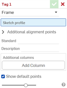
タグ用のフレームを選択します。
- [スケッチ輪郭] フィールドで、輪郭のスケッチとして機能するスケッチをフィーチャーリストから選択します。
-
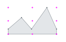
既定では、ダイアログの [既定点を表示] が有効になっています。これにより、マゼンタ色の 9 点位置合わせグリッドがスケッチプロファイルに重ねて配置されます。このオプションをオフにすると、位置合わせ点が非表示になります。

-
[追加の位置合わせ点] フィールドで、位置合わせに使用したいスケッチ内の他の点を選択します。
- [標準] フィールドに、カットリストテーブルの [標準] 列に表示する値を入力します。
- [説明] フィールドに、カットリストテーブルの [説明] 列に表示する説明を入力します。
- 輪郭にさらに多くの情報列を指定するには、[列を追加] をクリックします。
![[列を追加] を選択したタグプロファイルダイアログ](Resources/Images/feature-tools/frame-tagprofile-addcolumn-01-01.png)
-
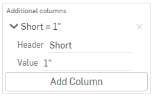
[ヘッダー] フィールドに、追加の輪郭のカットリストテーブルに表示する新しい列ヘッダーの名前と値を入力します。

-
[列を追加] をクリックして、別の列/値のペアをカットリストテーブルに追加します。
-
チェックマーク (
 ) をクリックします。
ベストプラクティスは、輪郭にタグを付け、バージョンを作成し、そのバージョンの輪郭をフレームで参照することです。

[説明] 列に新しい値が表示され、上記の [Short] 列には対応する値が追加されています。
輪郭の新しい情報は、フレームフィーチャーで使用された後にカットリストテーブルに表示され、続いてカットリストテーブルフィーチャーによってテーブルが作成されます。ウィンドウの右側にある ![]() をクリックして、テーブルパネルを開きます。
をクリックして、テーブルパネルを開きます。
フォームタグは、シートメタルモデルにマテリアルを追加したり、シートメタルモデルからマテリアルを削除したりするためのフォームフィーチャーとして使用するシートメタル以外のパーツを指定します。
パーツにタグを付けるには、次の操作を実行します。
- タグアイコン (
 ) をクリックして、タグダイアログを開きます。
-
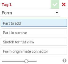
タグ用のフォームを選択します

- [追加するパーツ] フィールドで、パーツリストまたはグラフィック領域から、シートメタルに追加するパーツを選択します。
- [削除するパーツ] フィールドで、パーツリストまたはグラフィック領域から、シートメタルから削除するパーツを選択します。
- [展開図用のスケッチ] を選択します。このスケッチは、シートメタルモデルの展開図に使用されます。
- [フォームの原点の合致コネクタ] を選択します。これにより、シートメタルモデルでフォームが成形される方向が決まります。グラフィック領域でモデルにカーソルを合わせて、明示的または暗示的な合致コネクタを選択します。何も選択されていない場合は、フィーチャーによって Part Studio の原点に 1 つ作成されます。
- チェックマーク (
 ) をクリックします。
シートメタルパーツは選択せず、標準の幾何学的パーツを選択してください。
シートメタルパーツは選択せず、標準の幾何学的パーツを選択してください。
Part Studio ごとに作成できる有効なフォームタグフィーチャーは 1 つだけです。Part Studio ごとに 1 つのフォームを作成します。
-
 フレーム - 輪郭を共有するスイープボディのコレクションを作成し、端から端まで配置します。
 -
 フレームトリミング - 順序付けたグループとしてセグメントをトリミングします。
 -
 ガセット - 隣接するフレームセグメント間にガセットを作成します。
 -
 エンドキャップ - フレームセグメント用に 1 つまたは複数のエンドキャップを作成します。
 -
 カットリスト - フレーム内のすべてのセグメントの特性を持つカットリストを作成します。この操作により、コレクション用に開いたコンポジットパーツも作成されます。
 -
 タグ - フレームやパーツで使用するスケッチの輪郭エンティティにタグを付けて、シートメタルフォームに追加したり、シートメタルフォームから削除したりできます。ジオメトリを選択し、方向を定義して、プロパティを追加します。