 寸法
寸法
![]()
![]()
![]()
スケッチジオメトリおよびスケッチジオメトリと平面の間に、水平、垂直、最短距離、角度、直径、円弧長さ、半径寸法を追加します。従属寸法 (参照) または駆動寸法として寸法を指定できます。
ショートカット: d
測定ツールを使用して、グラフィック領域内のすべてのものを測定できます。
一部のツールでは、スケッチしながら寸法を指定できます。
スケッチのコンテキストメニュー (RMB) の [寸法を表示] コマンドを使用して、既存の寸法を表示することもできます。
寸法はスケッチエンティティを定義するための強力な方法です。スケッチに寸法を追加するには 2 つの方法があります。1 つ目はスケッチの作成時に寸法を追加する方法で、2 つ目は最初にスケッチジオメトリを作成してから寸法を追加する方法です。
スケッチに寸法を追加するには、ジオメトリをスケッチした後に数値を入力し、Enter キーを押します。たとえば、1 本の線を引き、2 番目の終点を選択すると、線の長さを示す白いボックスが表示されます。値を入力し、Enter を押すと寸法が割り当てられます。この方法は、ほぼすべてのスケッチツールで使えます。
長方形のように 2 次元のジオメトリを定義する場合は、まず水平寸法を入力して Enter キーを押します。入力は自動的に垂直寸法に切り替わります。
寸法を追加する 2 つ目の方法は、スケッチジオメトリの完成後に寸法を追加することです。寸法ツールを選択するか、ショートカット D を使用します。1 つまたは複数のエンティティを左クリックして寸法を適用します。カーソルを移動し、左クリックして寸法を配置します。寸法の値を入力し、Enter キーを押します。スケッチは、最初に配置した寸法に合わせて自動的にサイズが調整されます。
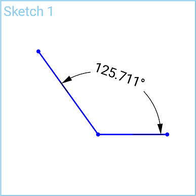
Onshape のスケッチ寸法は、選択したエンティティのタイプに直感的に対応します。これにより、円弧または円の外側または内側の寸法記入をシームレスに行えます。円弧または円の外側近くを左クリックして、外側の寸法を記入します。円弧または円の内側近くを左クリックして内側の寸法を記入します。寸法ツールではこれと同じ直感的な方法で、平行でない 2 本の線分の寸法を記入するときも、自動的に角度が記入されます。
寸法を編集するには、グラフィック内で寸法をダブルクリックします。新しい値を入力し、Enter を押して確定します。グラフィック領域から寸法を削除するには、削除する寸法を選択してキーボードの Delete キーを押します。寸法を使用して、他の寸法や関係によって駆動される値を表示することもできます。スケッチでは従属寸法は灰色で表示され、駆動寸法は黒で表示されます。配置によってスケッチが過剰に定義される場合は、新しい寸法を自動的に従動寸法に切り替えます。寸法の駆動状態を手動で切り替えるには、右クリックメニューを使います。
-
 をクリックするか、[D] キーを押します。
 - 寸法記入するエンティティ (1 つまたは複数) と、寸法の位置を選択します。
選択したエンティティつまたは複数のエンティティが強調表示され (ブラウザのみ)、寸法の配置に関するダイアログが開きます。
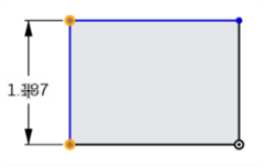
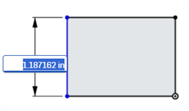
- 値を入力し、Enter を押して値を確定します。寸法に変数を使用することもできます。その場合は「=#」と変数名 (「=#d」など) を入力します。
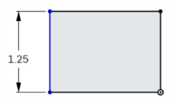
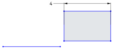
寸法 (長さ、直線距離、角度) に負の値を入力すると、エンティティの方向が反転します。
下の画像は正の寸法を示しています。一番下の水平線を基準とした長方形の位置に注意してください。
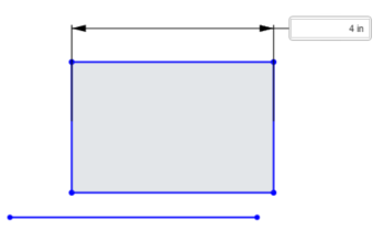
次の画像は、アクティブなフィールドに入力されている負の寸法値を示しています。
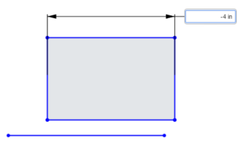
値を確定すると、長方形の方向が反転します。
-
Part Studio の数値フィールドでは、式と三角関数を使用できます。
-
寸法を選択して [削除] キーを押すか、寸法を選択してコンテキストメニューから [削除] を選択します。
-
配置の寸法を編集するには、値をダブルクリックしてフィールドをアクティブにし、新しい値を入力します。[Enter] キーを押して、変更を受け入れます。
-
直径寸法と半径寸法を除き、新しい寸法値を入力すると、寸法記入される両方の幾何学的選択が新しい入力値の半分だけ変換されるため、両方の幾何学的選択が等しく変換されます。たとえば、1 本の線分の寸法を記入する場合、各終点は寸法値の半分だけ平行移動されるため、両方の端点が等しく平行移動されます。
-
拘束されたジオメトリは変換されない場合があります。拘束操作を参照してください。
単線距離
- 寸法ツール (
 ) をクリックします。
 - 行をクリックします。
- ドラッグして直線距離寸法を配置します。
- クリックすると寸法が配置され、同時にその数値フィールドが開きます。
-
オプションで、新しい寸法値を入力します。
-
Enter を押して寸法値を確定します。

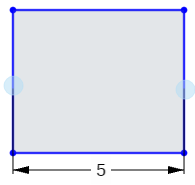
2 本の線間の距離
- 寸法ツール (
 ) をクリックします。
 - 1 行目をクリックします。
- 2 行目をクリックします。
- ドラッグして直線距離寸法を配置します。
- クリックすると寸法が配置され、同時にその数値フィールドが開きます。
-
オプションで、新しい寸法値を入力します。
-
Enter を押して寸法値を確定します。

2 本の線間に寸法を記入すると、視覚的に平行になるという拘束がなくても平行になります。
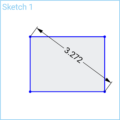
- 寸法ツール (
 ) をクリックします。
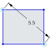
 - 1 番目のコーナー点をクリックします。
- 1 番目のコーナー点と対角にある 2 番目のコーナー点をクリックします。
- 斜めにドラッグして対角距離の寸法を配置します。
- クリックすると寸法が配置され、同時にその数値フィールドが開きます。
-
オプションで、新しい寸法値を入力します。
-
Enter を押して寸法値を確定します。
- 寸法ツール (
 ) をクリックします。
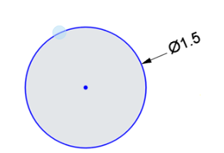
 - 円のエッジをクリックします。
- 円の内側または円から離れるようにドラッグして、直径寸法を配置します。
- クリックすると寸法が配置され、同時にその数値フィールドが開きます。
-
オプションで、新しい寸法値を入力します。
-
Enter を押して寸法値を確定します。
- 寸法ツール (
 ) をクリックします。
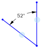
 - 1 本目の線をクリックします。
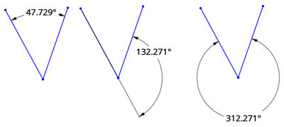
- 1 本目の線と角度をなす 2 本目の線をクリックします。
- 角度の内側または外側にドラッグして、角度寸法を配置します。
角度を定義したい四半円まで寸法をドラッグすることもできます。
- クリックすると寸法が配置され、同時にその数値フィールドが開きます。
-
オプションで、新しい寸法値を入力します。
-
Enter を押して寸法値を確定します。
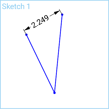
直接距離
この寸法は、2 点間の最短距離です。
- 寸法ツール (
 ) をクリックします。
 - 1 本目の線の終点をクリックします。
- 2 本目の線の終点をクリックします。
- 斜めにドラッグして直接距離の寸法を配置します。
- クリックすると寸法が配置され、同時にその数値フィールドが開きます。
-
オプションで、新しい寸法値を入力します。
-
Enter を押して寸法値を確定します。
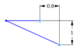
直線距離
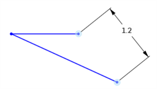
この寸法は、2 点間の直線距離です。
- 寸法ツール (
 ) をクリックします。
 - 1 本目の線の終点をクリックします。
- 2 本目の線の終点をクリックします。
- 直線距離寸法を配置するには、上下または左右にまっすぐドラッグします。
- クリックすると寸法が配置され、同時にその数値フィールドが開きます。
-
オプションで、新しい寸法値を入力します。
-
Enter を押して寸法値を確定します。
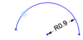
- 寸法ツール (
 ) をクリックします。
 - 円弧をクリックします。
- 円弧の内側または外側にドラッグして、半径寸法を配置します。
- クリックすると寸法が配置され、同時にその数値フィールドが開きます。
-
オプションで、新しい寸法値を入力します。
-
Enter を押して寸法値を確定します。
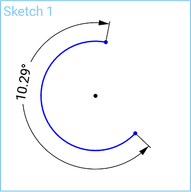
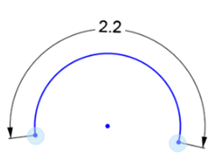
- 寸法ツール (
 ) をクリックします。
 -
円弧の 1 番目の終点をクリックします。
-
円弧の 2 番目の終点をクリックします。
-
円弧をクリックします。
-
ドラッグして円弧長寸法を配置します。
-
クリックすると寸法が配置され、同時にその数値フィールドが開きます。
-
オプションで、新しい寸法値を入力します。
-
Enter を押して寸法値を確定します。
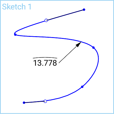
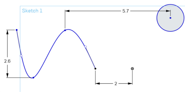
これにより、スプライン上の 2 点またはスプライン点と他のスケッチ点との距離が測定されます。
-
寸法ツール (
 ) をクリックします。
 -
1 番目のスプライン点をクリックします。
-
2 番目のスプライン点 (または他のスケッチ点) をクリックします。
-
ドラッグして距離寸法を配置します。
-
クリックすると寸法が配置され、同時にその数値フィールドが開きます。
-
オプションで、新しい寸法値を入力します。
-
Enter を押して寸法値を確定します。
また、カーソル角度をドラッグして直接距離寸法を配置すると、スプライン上の 2 点またはスプライン点と他のスケッチ点の間の直接距離を取得できます。直線距離を参照してください。
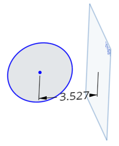
これにより、平面と他のスケッチ点との距離の寸法が記入されます。
-
寸法ツール (
 ) をクリックします。
 -
スケッチ点をクリックします。
-
平面をクリックします。
-
ドラッグして距離寸法を配置します。
-
クリックすると寸法が配置され、同時にその数値フィールドが開きます。
-
オプションで、新しい寸法値を入力します。
新しい寸法値を入力すると、平面はそのままスケッチジオメトリが移動します。
-
Enter を押して寸法値を確定します。
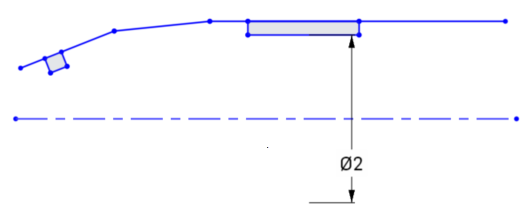
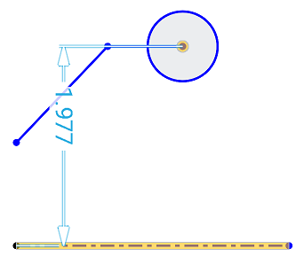
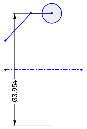
円、点、または非作図線と作図線との間に、中心線寸法を作成します。たとえば、回転操作のパーツに寸法を記入します。これらのスケッチエンティティの 1 つ間の距離寸法を開始し、作図線の反対側にマウスを移動します。作図線上でマウスを移動すると、距離寸法と中心線の寸法の状態が切り替わります。
-
寸法ツール (
 ) をクリックします。
 -
円またはスケッチ点をクリックします。
-
作図線をクリックします。これにより、2 本の線間の距離寸法が得られます。

- 作図線の反対側にドラッグすると、中心線寸法の状態を切り替えると同時に中心線寸法が配置されます。
- クリックすると寸法が配置され、同時にその数値フィールドが開きます。
-
オプションで、新しい寸法値を入力します。
-
Enter を押して寸法値を確定します。
被駆動寸法は、クリアランスや肉厚を特定の値を超えるなど、設計意図を維持するのに役立ちます。
- 既定では、寸法は駆動されます。寸法値を右クリックし、コンテキストメニューから [駆動/被駆動] を選択します。
- 駆動寸法は黒で表示され、編集できます。
- 従属寸法は薄い灰色で表示され、編集できません (必要に応じて、駆動寸法に切り替えてから編集します)。
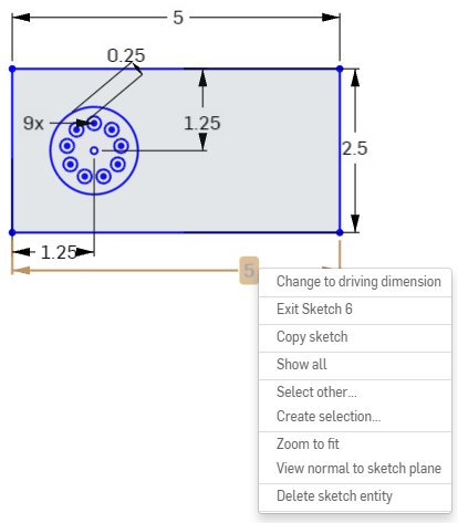
- スケッチに追加された寸法によってスケッチが過剰定義されると、寸法は自動的に「被駆動」にされます。
- 従属寸法は、駆動寸法を追加できる任意の場所に追加できます。
- 従属寸法は、暗黙の寸法の値を反映します。ジオメトリは変更されません。
- 寸法が被駆動から駆動に切り替わると、ジオメトリが変更されます。被駆動寸法を駆動に変更するとスケッチが過剰拘束される場合は、通常どおり赤いインジケータが表示されます。
Onshape では、一部の寸法に負の値を入力できますが、すべてには入力できません。負の値を受け入れる寸法については、以下を参照してください。
Onshape では、以下に対して負の値も使用できます。- 距離寸法
- 角度寸法
- 線の長さ
- スプライン寸法
- 円弧寸法
- 半径寸法または直径寸法
- [寸法] ツールをタップします。
- 寸法記入するエンティティ (1 つまたは複数) と、寸法の位置を選択します。
寸法の配置に関するダイアログが開きます。
- 値を入力し、チェックマークを選択して値を確定します。
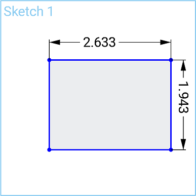
- タップしてコーナー点を選択します。
- 反対側のコーナー点をタップして選択します。
- 現在の値が表示され、それをタップしてテンキーを開きます。
- テンキーを使用して寸法を入力します。
- タップして、垂直線または水平線を選択します。
- 長さまたは高さの現在の値が表示され、それをタップしてテンキーを開きます。
- テンキーを使用して寸法を入力します。
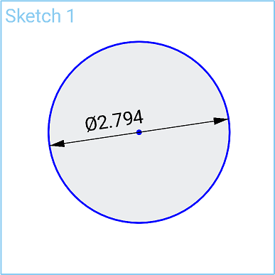
- 円のエッジをタップして選択します。
- 現在の値が表示され、それをタップしてテンキーを開きます。
- テンキーを使用して寸法を入力します。
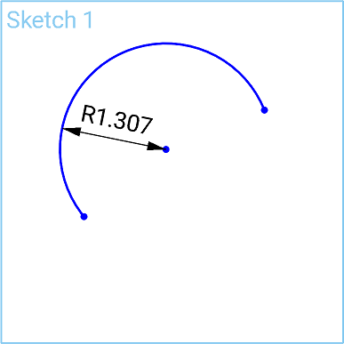
- 円弧のエッジをタップして選択します。
- 半径の現在の値が表示され、それをタップしてテンキーを開きます。
- テンキーを使用して寸法を入力します。
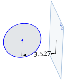
- タップして点を選択します。
- タップして平面を選択します。
- 現在の値が表示され、それをタップしてテンキーを開きます。
- テンキーを使用して寸法を入力します。
円、点、または非作図線と作図線との間に、中心線寸法を作成します。たとえば、回転操作のパーツに寸法を記入します。
- タップして寸法記入する点を選択します。
- 中心線として作成する作図線をタップして選択します。
点と作図線の間に寸法が設定されます。
- 作図線を交差する寸法をタッチしてドラッグします。
寸法が作図線と交差すると、作図線が中心線になり、それに応じて寸法が調整されます。
- 被駆動寸法は、クリアランスや肉厚を特定の値を超えるなど、設計意図を維持するのに役立ちます。
- 既定では、寸法は駆動されます。タップして寸法を選択し、2 本指でタップしてコンテキストメニューを表示します。コンテキストメニューでタップして寸法の ドライブ/駆動切り替え を行います。
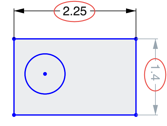
- 駆動寸法は黒で表示され、編集できます。
- 従属寸法は明るい灰色で表示され、編集することができます (従属寸法を駆動寸法に切り替えてから、必要に応じて編集します)。
- スケッチに追加された寸法によってスケッチが過剰定義されると、寸法は自動的に「被駆動」にされます。
- 従属寸法は、駆動寸法を追加できる任意の場所に追加できます。
- 従属寸法は、暗黙の寸法の値を反映します。ジオメトリは変更されません。
- 寸法が被駆動から駆動に切り替わると、ジオメトリが変更されます。被駆動寸法を駆動に変更するとスケッチが過剰拘束される場合は、通常どおり赤いインジケータが表示されます。
- [寸法] ツールをタップします。
- 寸法記入するエンティティ (1 つまたは複数) と、寸法の位置を選択します。
寸法の配置に関するダイアログが開きます。
- 値を入力し、チェックマークを選択して値を確定します。
- タップしてコーナー点を選択します。
- 反対側のコーナー点をタップして選択します。
- 現在の値が表示され、それをタップしてテンキーを開きます。
- テンキーを使用して寸法を入力します。

- タップして、垂直線または水平線を選択します。
- 長さまたは高さの現在の値が表示され、それをタップしてテンキーを開きます。
- テンキーを使用して寸法を入力します。

- 円のエッジをタップして選択します。
- 現在の値が表示され、それをタップしてテンキーを開きます。
- テンキーを使用して寸法を入力します。

- 円弧のエッジをタップして選択します。
- 半径の現在の値が表示され、それをタップしてテンキーを開きます。
- テンキーを使用して寸法を入力します。

- タップして点を選択します。
- タップして平面を選択します。
- 現在の値が表示され、それをタップしてテンキーを開きます。
- テンキーを使用して寸法を入力します。

円、点、または非作図線と作図線との間に、中心線寸法を作成します。たとえば、回転操作のパーツに寸法を記入します。
- タップして寸法記入する点を選択します。
- 中心線として作成する作図線をタップして選択します。
点と作図線の間に寸法が設定されます。
- 作図線を交差する寸法をタッチしてドラッグします。
寸法が作図線と交差すると、作図線が中心線になり、それに応じて寸法が調整されます。


- 被駆動寸法は、クリアランスや肉厚を特定の値を超えるなど、設計意図を維持するのに役立ちます。
- 既定で寸法はドライビング (駆動) です。寸法をダブルタップしてテンキーを開き、ドリブン/ドライビング ボタンをタップして寸法タイプを切り替えます。ボタンには、選択した寸法のタイプが表示されます。ボタンをタップすると、反対の寸法タイプに切り替わります。
- 駆動寸法は黒で表示され、編集できます。
- 従属寸法は明るい灰色で表示され、編集することができます (従属寸法をドライビングに切り替えてから、必要に応じて編集します)。

- スケッチに追加された寸法によってスケッチが過剰定義されると、寸法は自動的に「被駆動」にされます。
- 従属寸法は、駆動寸法を追加できる任意の場所に追加できます。
- 従属寸法は、暗黙の寸法の値を反映します。ジオメトリは変更されません。
- 寸法が被駆動から駆動に切り替わると、ジオメトリが変更されます。被駆動寸法を駆動に変更するとスケッチが過剰拘束される場合は、通常どおり赤いインジケータが表示されます。
