モデルベース定義 (MBD)
![]()
![]()
![]()
利用可能: Part Studio
モデルベース定義 (MBD) とは、Part Studio でモデルに寸法を記入して注釈を付けるプロセスを指します。これにより、製品の定義に必要なすべてのデータがモデルに含まれます。MBD では、モデルがすべてのエンジニアリング活動を推進するソース権限となります。このモデルは、下流のサプライヤーや組織全体でさらに使用される可能性があります。
MBD データは、スケッチやフィーチャーの寸法を許容範囲にする許容差オプションや、Part Studio で各パーツの MBD データを表示、追加、エクスポートできる検査テーブルと連携して機能します。
MBD は図面に代わるものではありません。MBD は、モデルの製品製造情報 (PMI) とモデルベースエンタープライズ (MBE) 情報を取得して拡張し、追加または代替の下流用途に使用することを目的としています。
MBD のフィーチャー:
-
Part Studio のモデルに埋め込まれた寸法と注釈のメタデータ。
-
Part Studio のモデルでのリアルタイムコラボレーションを改善します。
-
組織全体のエンジニアに信頼できる唯一の情報源を提供します。
-
三次元測定機 (CMM) 検査のような下流プロセスへのリンク。

駆動 MBD のスケッチとフィーチャーの寸法は、グラフィック領域から直接編集できます。
製品の製造情報は、検査テーブルが開いているときにグラフィック領域で編集できます。また、最初に定義されていたスケッチやフィーチャー内でも編集できます。
グラフィック領域で寸法をダブルクリックして許容差を編集します。寸法がフィーチャーリストを参照している場合、Onshape はスケッチまたはフィーチャーを開いて編集します。注釈ツールバーを使用して寸法を作成した場合は、グラフィック領域で編集します。モデルと許容差が変わると、検査テーブルはリアルタイムで更新されます。
特性テーブルで、2 つの切り替えボタンを使用して行を絞り込みます。最初は、既定の許容差が適用された注釈が表示され、派生ジオメトリの注釈は非表示になります。派生注釈を更新するには、ソースを変更します。
クロスハイライトを使用すると、関連するモデル参照をすばやく特定できます。検査テーブルのセルにカーソルを合わせると、グラフィック領域の参照パーツ、面、フィーチャー、および関連する注釈がクロスハイライトされます。グラフィック領域で注釈を選択するか、データムまたはタイプセルをクリックしてハイライトを表示したままにします。
注釈を削除するには、グラフィック領域で注釈を選択して [削除] を押します。フィーチャーリストを参照している注釈を削除すると、スケッチの寸法またはフィーチャー値から許容差オプションが削除され、特性テーブルからその行が削除されます。注釈ツールバーで配置された注釈を削除すると、その注釈はテーブルから削除されます。派生した注釈は削除できません。
-
検査パネル (
 ) を開き、グラフィック領域に MBD の寸法を表示します (下の左の画像)。
 -
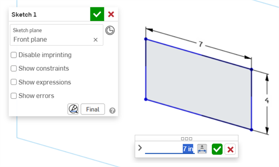
スケッチに関連付けられている駆動寸法をダブルクリックします (下の右の画像):
寸法コンテキストダイアログが開き、寸法値にコンテキストが配置されます。同時に、スケッチダイアログが開きます。
-
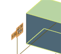
キーボードを使って数値を入力するか、上/下矢印を使って寸法コンテキストダイアログの値を増やします。この値を調整すると、スケッチは動的に更新されます。
値を数値で入力する場合は、Tab キーを押してスケッチの値を更新します。
-
キーボードで Enter キーを押すか、寸法コンテキストダイアログのチェックマーク (
 ) をクリックしてこのダイアログを閉じます。
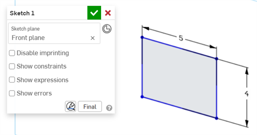
-
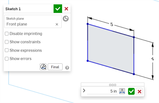
スケッチダイアログのチェックマーク (
) を押して、新しいスケッチ値を確定します。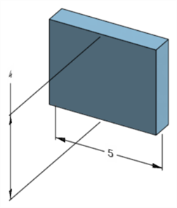
モデルの寸法を調整する編集済みのスケッチ寸法
-
検査パネル (
) を開き、グラフィック領域に MBD の寸法を表示します (下の左の画像)。 -
フィーチャーに関連付けられている駆動寸法をダブルクリックします (下の右の画像):
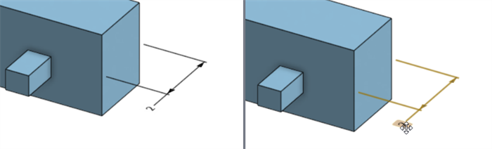
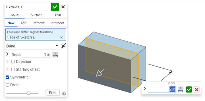
寸法コンテキストダイアログが開き、寸法値にコンテキストが配置されます。同時に、関連する機能ダイアログが開きます (この例では押し出し):
-
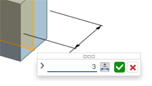
キーボードを使って数値を入力するか、上/下矢印を使って寸法コンテキストダイアログの値を増やします。この値を調整すると、フィーチャーダイアログのモデルと値は動的に更新されます。
値を数値で入力する場合は、Tab キーを押してフィーチャーダイアログの値を更新します。
-
キーボードで Enter キーを押すか、寸法コンテキストダイアログのチェックマーク (
) をクリックしてこのダイアログを閉じます。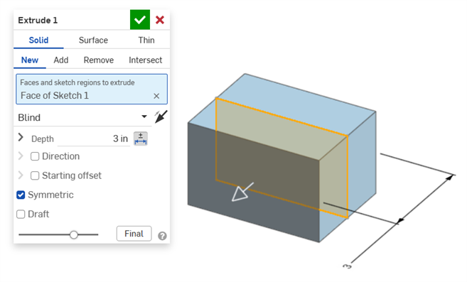
-
キーボードで Enter キーをもう一度押すか、フィーチャーダイアログのチェックマーク (
) をクリックしてこのダイアログを閉じます。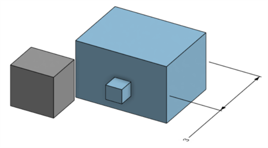
モデルの寸法を調整する編集済みのフィーチャー寸法
注釈を削除するには、次の手順に従ってください。
-
グラフィック領域で注釈を選択します。
-
Delete キーを押します。
-
注釈はグラフィック領域と検査テーブルから削除されます。
注釈がスケッチまたはフィーチャー寸法の場合:
-
寸法の許容差オプションの値は削除されます。
-
許容差オプションアイコン (
 ) は選択解除されます。
 -
スケッチまたはフィーチャーダイアログの寸法値は削除されません。
-
次の場合は注釈を削除できません。
-
派生した注釈。
-
パラメータに許容差が設定されているが、許容差の切り替えがユーザー入力に使用できないカスタムフィーチャーで作成された注釈。
いずれの場合も、次のメッセージが表示されます。

-
従属寸法は編集できません。従属寸法をダブルクリックすると、寸法コンテキストダイアログが開きますが、ダイアログの値は編集できません。
-
派生寸法は編集できません。派生パーツの駆動寸法または従属寸法をダブルクリックしても、寸法コンテキストダイアログは開きません。
-
寸法コンテキストダイアログをキャンセルするには、Esc キーを押します。フィーチャーの寸法を編集すると、寸法コンテキストダイアログとフィーチャーダイアログが同時に閉じます。スケッチの寸法を編集すると、寸法コンテキストダイアログだけが閉じます。スケッチダイアログは手動で閉じる必要があります (x アイコンをクリック)。
-
あるいは、フィーチャーダイアログと寸法コンテキストダイアログの両方を開いて、フィーチャーダイアログの値を選択して編集することができます。これにより、寸法コンテキストダイアログとモデルの両方が動的に更新されます。ここで編集して、Enter を押すと、フィーチャーダイアログと寸法コンテキストダイアログの両方が同時に閉じます。
-
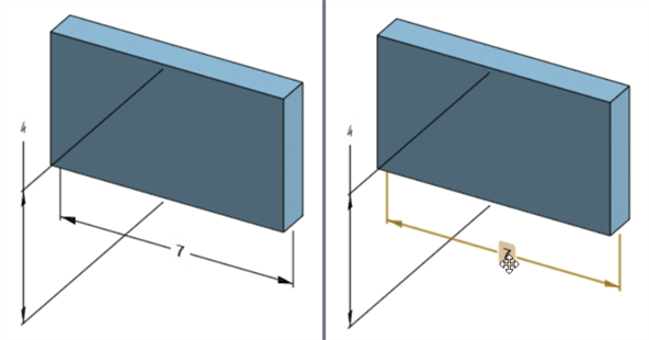
モデル寸法の位置とそれに対応するスケッチ寸法の位置は相互に固定されず、個々に独立しています:
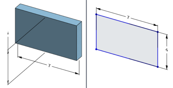
モデルの幅寸法は、モデルの下 (左) とスケッチ (右) の上
-
再生一時停止モードでは、モデル寸法の編集/削除はできません。ただし、フィーチャーを編集したり、寸法の許容差のオン/オフの切り替えはできます。変更は、[再生を一時停止中] バナーで [フィーチャーを再生して終了] をオフにすると有効になります。
-
コンフィギュレーションは想定どおりに機能しますが、寸法コンテキストダイアログの寸法は、構成済みであることを示すオレンジ色の破線で囲まれません。構成したスケッチ寸法は編集できません。
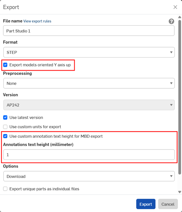
MBD データは、パーツをエクスポートするときに STEP 形式にエクスポートできます。次の設定が推奨されます。
閉じた複合部品の MBD データはエクスポートされません。この警告は、ドキュメントが開いている場合、エクスポート中にエクスポートダイアログに表示されます。ただし、高度な検索のドキュメントの結果リストからパーツを選択してエクスポートした場合、警告は表示されませんが、MBD データはエクスポートされません。
-
[Y 軸を上向きにしてモデルをエクスポート] をオンにします。
-
モデルのサイズによっては、[MBD エクスポートにカスタムの注釈のテキストの高さを使用] を有効にして、モデルのサイズに対して適切な [注釈のテキストの高さ] を選択する必要がある場合があります。
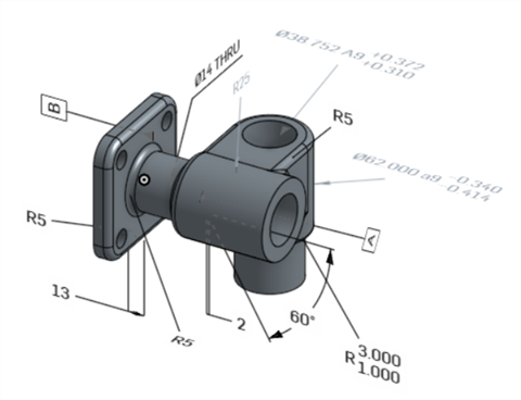
Onshape のオリジナルモデル
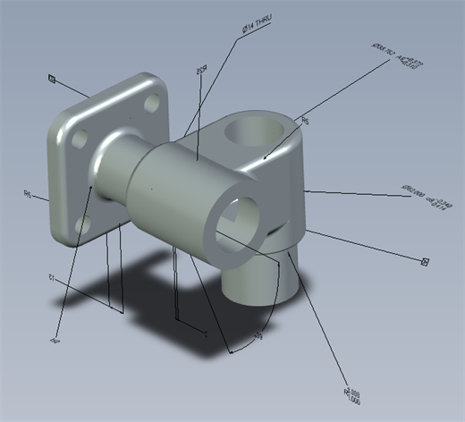
[MBD エクスポートにカスタムの注釈のテキストの高さを使用] をオフにしてエクスポートしたモデル
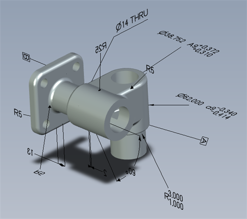
[MBD エクスポートにカスタムの注釈のテキストの高さを使用] をオンにし、10mm に設定してエクスポートしたモデル
エクスポートすると、複数の公差フレームを持つ幾何公差は、上のテキストが上のフレームに組み合わされ、下のテキストが下のフレームに組み合わされます。
以下に、フィーチャーと寸法公差を使用する場合の MBD の例を示します。
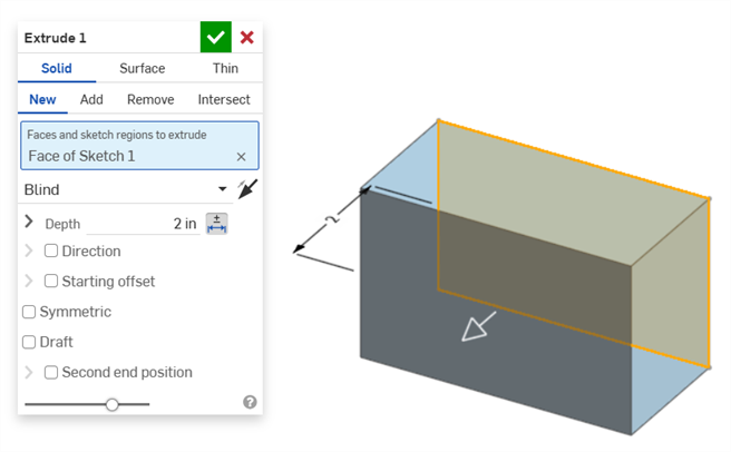
奥行きの寸法:
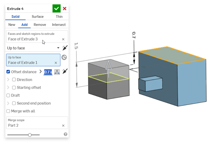
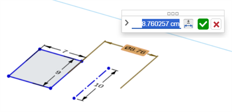
オフセット距離の寸法 (複合部品を含む):
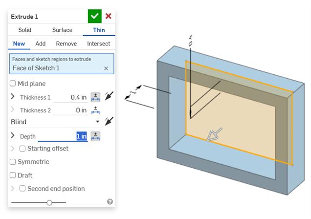
薄い押し出し (厚さ 1 と奥行きの寸法):
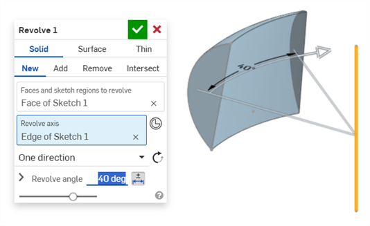
回転 (回転角の寸法):
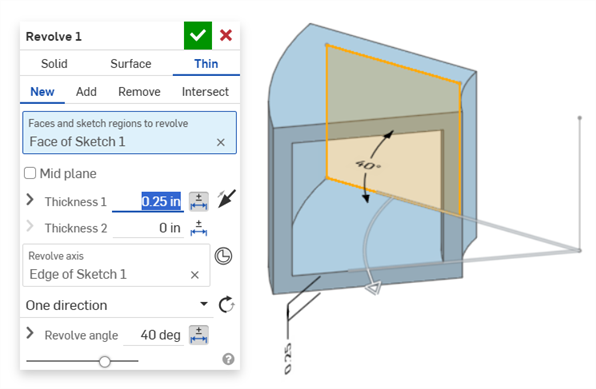
回転 (厚さ 1 と回転角の寸法):
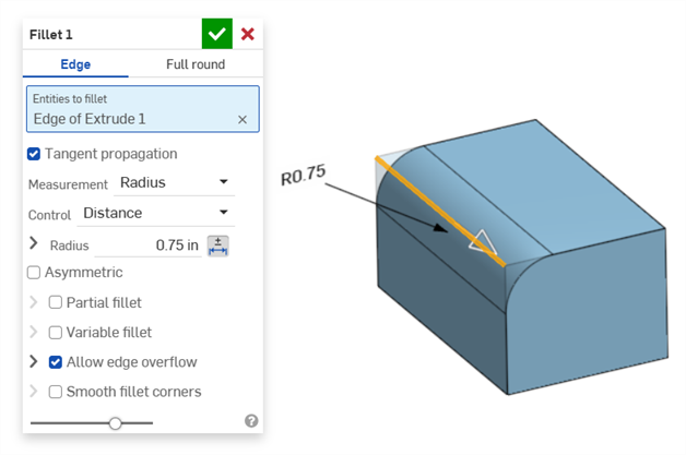
フィレット (半径の寸法):
検査テーブルの注釈ツールバーにあるフィレット寸法ツールを使用して、従属フィレット寸法の作成します。

検査パネルの寸法ツール (![]() ) は常に線形または角度の既定の許容差を使用します。これを使用してフィレット面の寸法を記入すると、線形の既定の許容差タイプが適用されます。このため、フィレットフィーチャーダイアログからフィレットの許容差を適用するか (駆動寸法の場合)、検査パネルのフィレット寸法 (従属寸法の場合) を使用することをお勧めします。
) は常に線形または角度の既定の許容差を使用します。これを使用してフィレット面の寸法を記入すると、線形の既定の許容差タイプが適用されます。このため、フィレットフィーチャーダイアログからフィレットの許容差を適用するか (駆動寸法の場合)、検査パネルのフィレット寸法 (従属寸法の場合) を使用することをお勧めします。

フィレット面の寸法記入 (時計回りに注釈): 寸法ツールを使用 (従属、グレーの注釈)、フィレットの寸法ツールを使用 (従属、グレーの注釈)、フィレットフィーチャーの半径値を許容範囲にする (駆動、黒色の注釈)。3 つの寸法はすべて特性テーブルに記載されています。
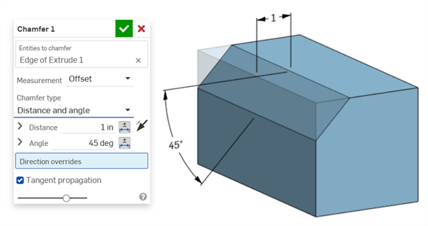
面取りは、角度までの距離または面とエッジの間の距離までの距離と定義されます。面取り幅の寸法は、エッジから仮想交点までの距離として指定されます。仮想交点の表示は、破線を含む寸法が記入されたエッジに追加されます。
-
接線測定を使用する場合、許容差は無効になりません。特定のケースでは、特に指定された許容差を考慮する場合に有効なためです。
-
2 つの面取り測定を使用する場合 (2 つの距離または距離と角度)、両方の公差を設定する必要はありません。許容差は、必要に応じて 1 つのパラメータにのみ追加できます。
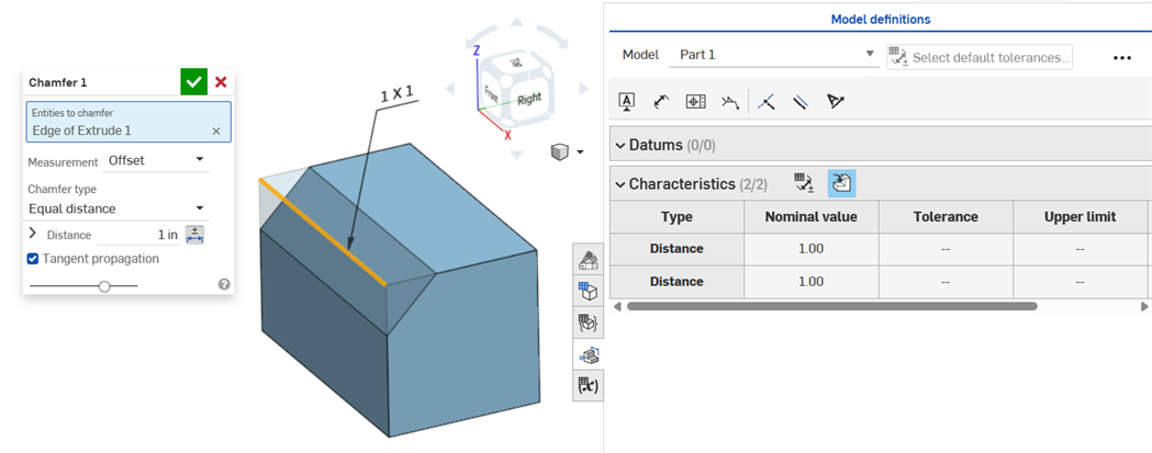
等距離の面取りタイプでは、ダイアログに距離公差オプションが 1 つしかありませんが、2 つの距離公差が表示され、テーブルに反映されます。
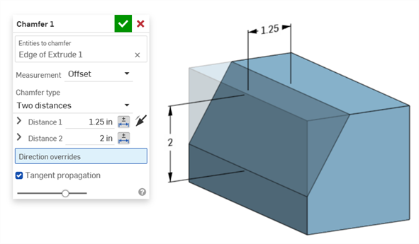
2 つの距離の例:
距離と角度の例:
面取りの結果、距離が可変になる場合 (たとえば、別の円柱に垂直に接続されている円柱面に面取りを適用する場合)、測定値に接線を選択し、エッジに沿って距離が均一になるようにします。
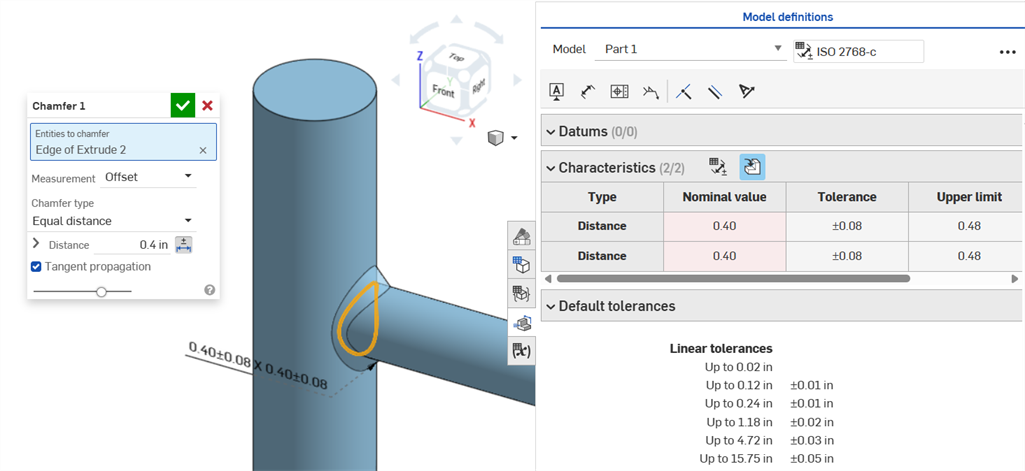
オフセット測定を使用した不均一な面取りで公称誤差を表示。
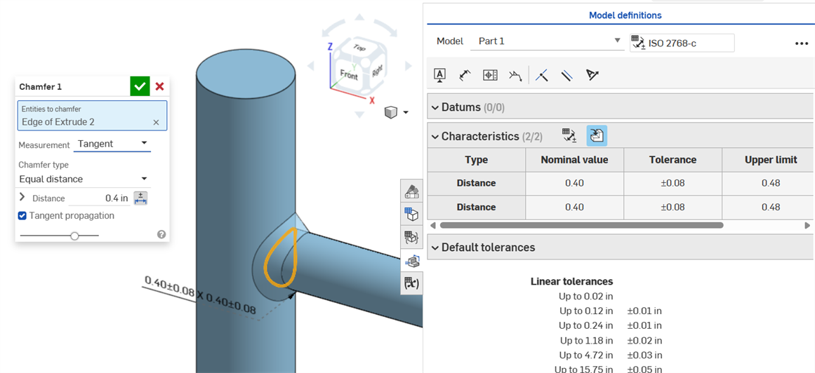
接線測定値を使用して均一に面取りすると、誤差のない公称値が得られます。
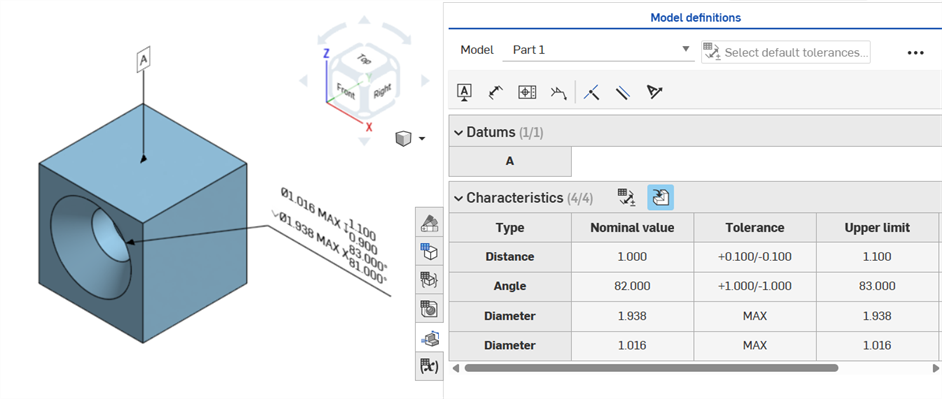
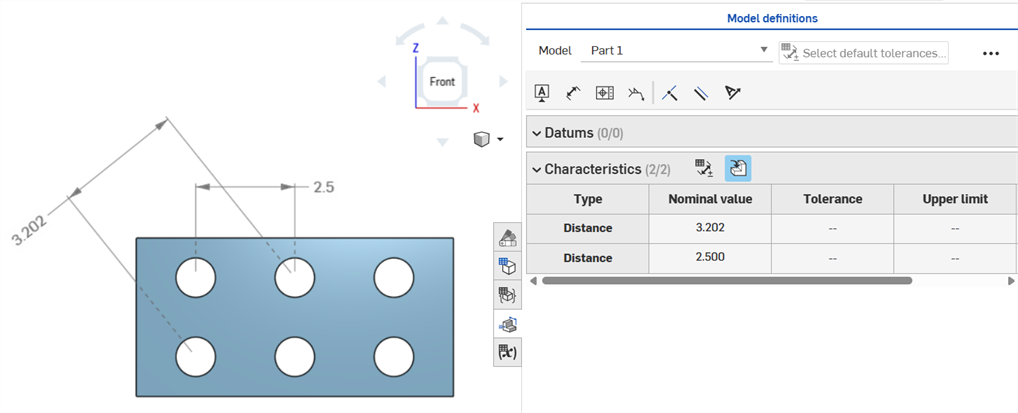
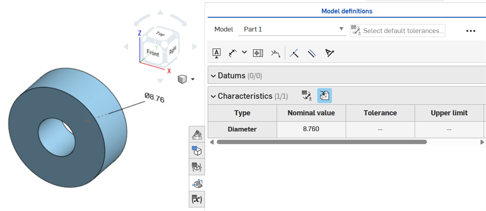
穴フィーチャーに公差を設定すると、検査テーブルに表示できます。
注意事項:
-
穴の寸法は、検査テーブルの行にのみ表示されます。グラフィック領域ではコールアウトで乱雑にならないようにするため、寸法は表示されません。
-
穴の寸法を検査テーブルに表示する前に、パーツに別のコールアウト (データムなど) を配置する必要があります。
-
1 つの穴フィーチャーには 1 セットの寸法 (直径、距離、角度) のみが表示されます。パターン化された穴や同じフィーチャー内の追加の穴は、個別に寸法が記入されません。
-
カスタムの先端角度の寸法は現在サポートされておらず、検査テーブルに行は作成されません。
-
クロスハイライトは次のように機能します。
-
穴の両エッジには面がなく、エッジは現在 MBD ではサポートされていないため、距離 (深さ) はクロスハイライトされません。
-
直径、距離 (カウンターボアの深さ)、角度 (カウンターシンクの角度) は、1 つの面をクロスハイライトします。
-
パーツのいずれかの面にデータムを追加すると、穴の寸法が検査テーブルに表示されます。
寸法 (![]() ) ツールを使った中心円間の軸距離寸法:
) ツールを使った中心円間の軸距離寸法:
最小寸法ツール (![]() ) を使用した、2 つの円筒面間の水平、対角線、垂直の最小寸法:
) を使用した、2 つの円筒面間の水平、対角線、垂直の最小寸法:

円柱とエッジの間の最小寸法:

パーツが作成されると (右)、スケッチに追加された最小対角寸法が特性テーブルに表示されます (左):

現在、水平および垂直の最小寸法はスケッチでは作成できません。
最大寸法ツール (![]() ) を使用した、2 つの円筒面間の水平、対角線、垂直の最小寸法:
) を使用した、2 つの円筒面間の水平、対角線、垂直の最小寸法:

円筒とエッジの間の最大寸法:

スロット内の円弧面の間の水平、対角線、垂直の最大寸法:

パーツが作成されると (右)、スケッチに追加された最大対角寸法 (左) が特性テーブルに表示されます:
現在、水平方向と垂直方向の最大寸法はスケッチでは作成できません。
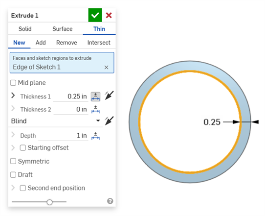
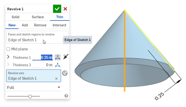
厚さは検査テーブルに距離行として表示されます。
薄い押し出し (厚み 1 寸法):
薄い回転 (厚み 1 寸法):
許容差を有効にしたスケッチの中心線寸法:
中心線がスケッチジオメトリを回転させる軸として使用されている場合、検査テーブルを開くと直径寸法として表示されます。
注釈を追加し、モデルを変更し、フィーチャーの更新を適用すると、関連する MBD データが自動的に検証されます。
検証はパーツごとに行われるため、注釈は同じパーツまたは複合部品のジオメトリを参照する必要があります。
特性が無効になると、注釈と検査表の対応する特性が両方とも赤で表示されます。
無効な特性は、参照の欠落と値の不一致という 2 つのカテゴリに分類されます。
参照の欠落は、特性の定義に使用されるジオメトリがもはや存在しないか、関連付けを切断するような方法で変更された場合に発生します。これは、フィーチャーの削除、面の置換、またはその他のトポロジーに関する変更が原因になります。
値の不一致は、参照ジオメトリの値が定義された許容差と一致しなくなった場合に発生します。これは、たとえば、穴の直径が指定された制限を超えて大きくなったことなどが原因になります。
考えられる原因を評価して、無効な特性を解決してください。
比較を使用するときは、面を選択すると関連付けられている注釈、許容差、特性が表示されます。
フィーチャーリストと MBD の注釈を変更して、エラーを検証して解決してください。
MBD エラーがあると、モデルを調整して既存の注釈行の入力を無効にしない限り、検査テーブルに注釈や行エントリは作成されません。
エラーは、Onshape の他のエラーと同様に赤で表示されます。

SOLID からの押し出し、または SOLID への押し出し時にエラーが発生しました。この注釈は、検査テーブルに行エントリを生成しません。
ジオメトリを変更した結果、指定した注釈が無効になった場合、その注釈はエラーであることを示すため、グラフィック領域と検査テーブルでは赤で強調表示されます。たとえば、箱の上面を 0.5 インチ移動した結果、測定した値 (3.5 インチ) と指定した値 (3.0 インチ) が異なる場合などです。
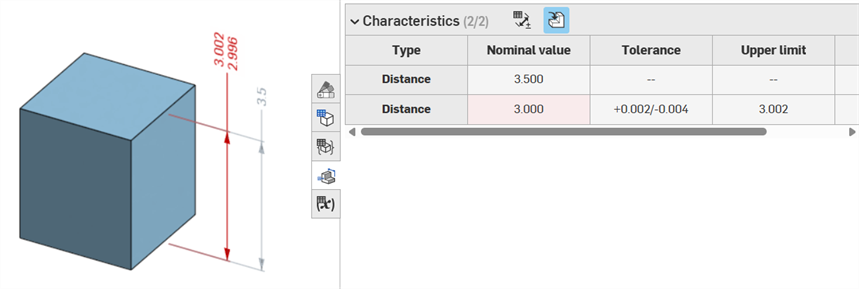
エラーの例
-
この注釈には参照がありません - 参照がない場合に発生します。たとえば、パーツ A をパーツ B の面まで押し出し、パーツ A の押し出し深さのオフセット距離に許容差を追加した場合などです。
-
両面が同じパーツでできている必要があります - モデル定義はパーツごとのみ有効です。たとえば、パーツ A の面からパーツ B の面までの距離を測定することはできません。
-
MBD の注釈は常に面に関連付けられている必要があります。エッジと頂点は現在は参照できません。
-
モデル定義はパーツごとにのみ有効です。複合部品も有効です。たとえば、パーツ A の 2 つの面またはパーツ B の 2 つの面の間の距離の寸法を記入できますが、パーツ A の面とパーツ B の面の間の距離の寸法を記入することはできません。これを行うには、まずパーツ A とパーツ B の両方で複合部品 C を作成し、次にこの 2 つの面の間の距離の寸法を記入できます。
-
検査テーブルのタイプ行にカーソルを合わせると、グラフィック領域の寸法がクロスハイライトされます。
-
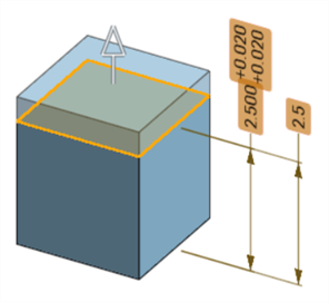
パーツのジオメトリを変更すると、関連するすべてのモデル定義がオレンジ色で強調表示されます。
-
パーツまたは Part Studio を派生フィーチャーを介して派生した場合、すべてのモデル定義は読み取り専用になり編集できません。派生ジオメトリを変更しても注釈は移動でき、従属寸法は引き続き更新されます。ただし、基になるモデル定義はソースのPart Studio でのみ調整でき、派生フィーチャーで更新します。詳細は、派生を参照してください。
-
グラフィック領域では、コメントを追加して、許容差のスケッチ寸法、フィーチャー寸法、穴コールアウト、および検査テーブルの注釈 (寸法、データム、幾何公差) にタグ付けできます。詳細は、MBD 注釈へのコメントの追加を参照してください。