Model-Based Definition (MBD)
![]()
![]()
![]()
Disponibile in: Part Studio
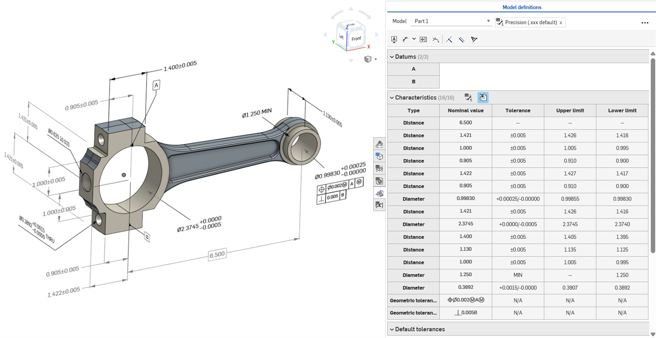
La Model-based definition (MBD) si riferisce al processo di quotatura e annotazione del modello all'interno di Part Studio in modo che il modello contenga tutti i dati necessari per definire un prodotto. Con la MBD, il modello diventa l'autorità di origine che guida tutte le attività di progettazione. Questo modello può essere ulteriormente utilizzato a valle dai fornitori e da tutte le organizzazioni.
I dati MBD funzionano insieme alle Opzioni di tolleranza, dove le dimensioni dello schizzo e della funzione vengono rese tollerate, e alla Tabella di ispezione, dove è possibile visualizzare, aggiungere ed esportare i dati MBD per ciascuna parte in un Part Studio.
La MBD non è intesa a sostituire i Disegni. La MBD punta ad acquisire ed estendere le informazioni per la produzione del prodotto (PMI) e le informazioni Model-based enterprise (MBE) per un utilizzo a valle aggiuntivo o alternativo.
Alcune funzioni di MBD:
-
Metadati di quotatura e annotazione integrati nel modello all'interno di Part Studio.
-
Migliora la collaborazione in tempo reale sul modello all'interno di Part Studio.
-
Fornisce un'unica fonte di verità per i progettisti in tutta l'organizzazione.
-
Collegamento a processi a valle come l'ispezione tramite macchine di misura a coordinate (CMM).
Le quote dello schizzo e della funzione MBD possono essere modificate direttamente dall'area grafica.
Le informazioni sulla produzione del prodotto possono essere modificate nell'area grafica quando la tabella di ispezione è aperta, nonché all'interno degli schizzi e delle funzioni in cui sono state originariamente definite.
Modifica le tolleranze facendo doppio clic sulla quota nell'area grafica. Se la quota fa riferimento all'elenco Funzioni, Onshape apre lo schizzo o la funzione per la modifica. Se la quota è stata creata utilizzando la barra degli strumenti Annotazione, modificala dall'area grafica. Man mano che il modello e le tolleranze cambiano, la tabella di ispezione si aggiorna in tempo reale.
Nella tabella Caratteristiche, filtra le righe utilizzando i due pulsanti di attivazione/disattivazione. Inizialmente, vengono mostrate le annotazioni con le tolleranze predefinite applicate, mentre le annotazioni provenienti dalla geometria derivata sono nascoste. Le annotazioni derivate possono essere aggiornate solo modificando l'origine.
Usa l'evidenziazione incrociata per identificare e individuare rapidamente i riferimenti associati al modello. Passa il cursore del mouse sulle celle della tabella di ispezione per evidenziare la parte referenziata, le facce, le funzioni e le annotazioni associate nell'area grafica. Seleziona un'annotazione nell'area grafica oppure fai clic su una cella Riferimento o Tipo per mantenere visibile l'evidenziazione.
Rimuovi un'annotazione selezionandola nell'area grafica e premendo Elimina. L'eliminazione di un'annotazione che fa riferimento all'elenco Funzioni rimuove le opzioni di tolleranza dalla quota dello schizzo o dal valore della funzione ed elimina la riga dalla tabella Caratteristiche. L'eliminazione di un'annotazione inserita tramite la barra degli strumenti delle annotazioni la rimuove dalla tabella. Le annotazioni derivate non possono essere eliminate.
-
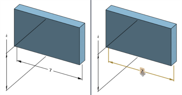
Apri il pannello Ispezione (
 ) per visualizzare le quote MBD nelle aree grafiche (immagine a sinistra qui sotto).
 -
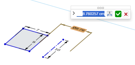
Fai doppio clic sulla dimensione guida associata a uno schizzo (immagine a destra qui sotto):
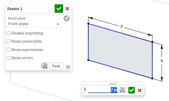
Viene aperta la finestra di dialogo contestuale della Quota, con il contesto posizionato sul valore dimensione. Contemporaneamente, si apre la finestra di dialogo dello Schizzo:
-
Tramite la tastiera, inserisci un valore numerico o utilizza le frecce su/giù per incrementare il valore nella finestra di dialogo contestuale della Quota. Man mano che il valore viene regolato, lo schizzo si aggiorna dinamicamente.
Se inserisci un valore numerico, premi il tasto Tab per visualizzare l'aggiornamento del valore dello schizzo.
-
Premi Invio sulla tastiera o fai clic sul segno di spunta (
 ) nella finestra di dialogo contestuale della quota per chiuderla:
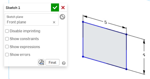
-
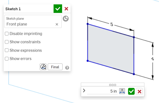
Premi il segno di spunta (
) nella finestra di dialogo dello Schizzo per accettare il nuovo valore dello schizzo.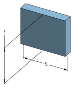
La quota dello schizzo modificata che aggiorna la dimensione del modello
-
Apri il pannello Ispezione (
) per visualizzare le quote MBD nelle aree grafiche (immagine a sinistra qui sotto). -
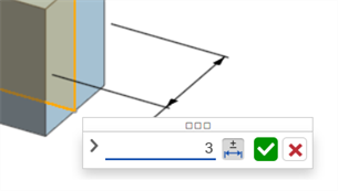
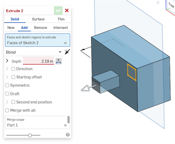
Fai doppio clic sulla dimensione guida associata a una funzione (immagine a destra qui sotto):
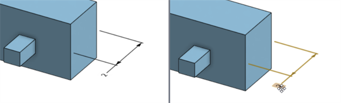
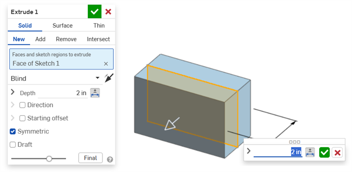
Viene aperta la finestra di dialogo contestuale della Quota con il contesto posizionato sul valore della dimensione. Contemporaneamente, si apre la finestra di dialogo della Funzione associata (Estrusione in questo esempio):
-
Tramite la tastiera, inserisci un valore numerico o utilizza le frecce su/giù per incrementare il valore nella finestra di dialogo contestuale della Quota. Man mano che il valore viene regolato, sia il modello sia il valore nella finestra di dialogo della Funzione si aggiornano dinamicamente.
Se inserisci un valore numerico, premi il tasto Tab per visualizzare il valore aggiornato nella finestra di dialogo della Funzione.
-
Premi Invio sulla tastiera o fai clic sul segno di spunta (
) nella finestra di dialogo contestuale della Quota per chiuderla: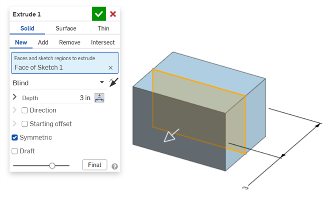
-
Premi nuovamente Invio sulla tastiera o fai clic sul segno di spunta nella finestra di dialogo della Funzione (
) per chiuderla: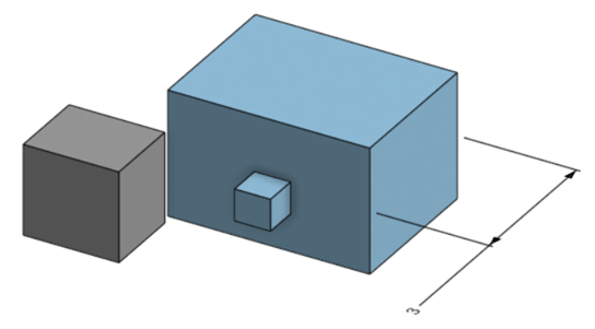
La quota della funzione modificata che aggiorna la dimensione del modello
Per eliminare un'annotazione:
-
Seleziona l'annotazione nell'area grafica:
-
Premi il tasto Canc.
-
L'annotazione viene eliminata dall'area grafica e dalla Tabella di ispezione.
Se l'annotazione è una quota di uno schizzo o di una funzione:
-
I valori delle Opzioni di tolleranza della quota vengono eliminati.
-
L'icona delle Opzioni di tolleranza (
 ) è deselezionata.
 -
Il valore della quota nello schizzo o nella finestra di dialogo della Funzione non viene eliminato.
-
Le annotazioni non possono essere eliminate se:
-
L'annotazione è derivata.
-
L'annotazione viene creata in una funzione personalizzata in cui il parametro è impostato come tollerante ma l'opzione di attivazione/disattivazione della tolleranza non è resa disponibile per l'input dell'utente.
In entrambi i casi viene visualizzato il seguente messaggio:

-
Le dimensioni guidate non possono essere modificate. Facendo doppio clic su una dimensione guidata si apre la finestra di dialogo contestuale della Quota, ma i valori al suo interno non possono essere modificati.
-
Le dimensioni derivate non possono essere modificate. Facendo doppio clic su una dimensione guida o guidata da una parte derivata non si apre la finestra di dialogo contestuale della Quota.
-
Per annullare e uscire dalla finestra di dialogo contestuale della Quota, premi il tasto Esc. Se stai modificando una quota di una funzione, la finestra di dialogo contestuale della Quota e quella Funzione si chiudono contemporaneamente. Se stai modificando una quota di uno schizzo, si chiude solo la finestra di dialogo contestuale della Quota. La finestra di dialogo dello schizzo deve essere chiusa manualmente (facendo clic sull'icona x).
-
In alternativa, con le finestre di dialogo contestuali della Funzione e della Quota aperte, è possibile selezionare e modificare il valore nella finestra di dialogo della Funzione; questo aggiornerà dinamicamente sia la finestra di dialogo contestuale della Quota sia il modello. Una volta apportata questa modifica, premendo Invio si chiuderanno contemporaneamente le finestre di dialogo contestuali della Funzione e della Quota.
-
La posizione della quota del modello e la posizione della corrispondente quota dello schizzo non sono vincolate tra loro. Sono indipendenti:
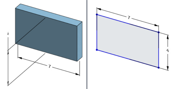
La quota della larghezza del modello si trova sotto il modello (a sinistra) ma sopra lo schizzo (a destra)
-
In modalità Pausa rigenerazione, la quota del modello non può essere modificata o eliminata. Tuttavia, è ancora possibile modificare la funzione o attivare o disattivare la tolleranza di una quota. Le modifiche hanno effetto dopo aver fatto clic sul segno di spunta Rigenera funzioni ed esci nel banner Rigenerazione in pausa.
-
Le configurazioni funzionano come previsto. Tuttavia, la quota nella finestra di dialogo contestuale della Quota non è circondata da un contorno arancione tratteggiato per indicare che è configurata. Le quote dello schizzo configurato non possono essere modificate.
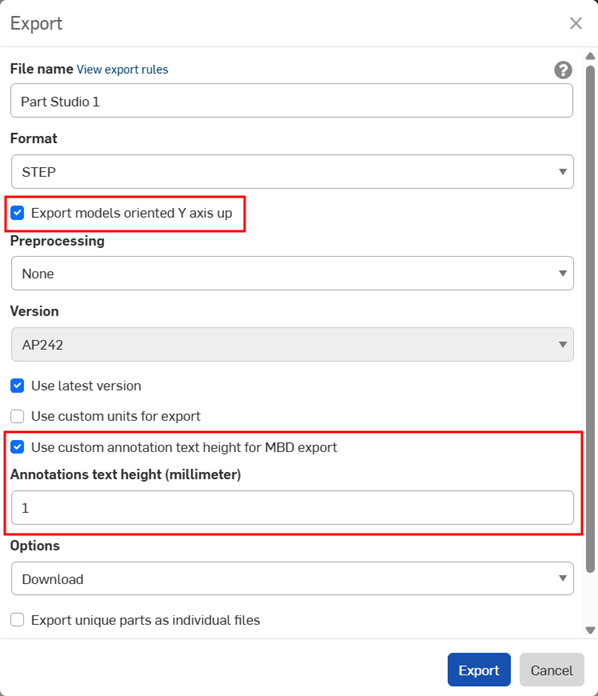
I dati MBD possono essere esportati in formato file STEP durante l'esportazione di parti. Sono consigliate le impostazioni seguenti:
I dati MBD non sono esportati per le parti composite chiuse. Questo avviso è visualizzato durante l'esportazione nella finestra di dialogo Esporta se il documento è aperto. Tuttavia, se una parte è selezionata ed esportata da un elenco dei risultati di ricerca avanzata documenti, l'avviso non viene visualizzato, ma i dati MBD non sono comunque esportati.
-
Abilita la casella di controllo Esporta modelli orientati con l'asse Y verso l'alto.
-
A seconda delle dimensioni del tuo modello, potresti dover abilitare l'opzione Usa altezza testo annotazione personalizzata per esportazione MBD e selezionare un'Altezza testo annotazioni appropriata che corrisponda alle dimensioni del tuo modello.
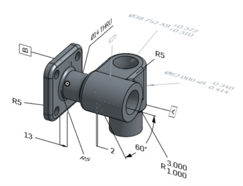
Modello originale in Onshape
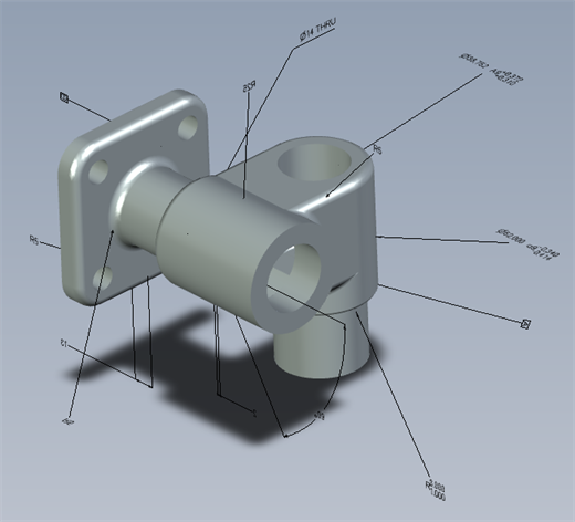
Modello esportato con l'opzione "Usa altezza testo annotazione personalizzata per esportazione in MBD" disattivata
Modello esportato con l'opzione "Usa altezza testo annotazione personalizzata per esportazione MBD" abilitata e impostata a 10 mm.
Durante l'esportazione, le tolleranze geometriche con più cornici di tolleranza presentano il testo superiore unito alla cornice superiore e il testo inferiore unito alla cornice inferiore.
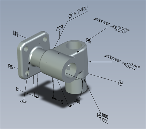
Di seguito sono riportati esempi di MBD relativi all'utilizzo di le tolleranze di Funzione e quota:
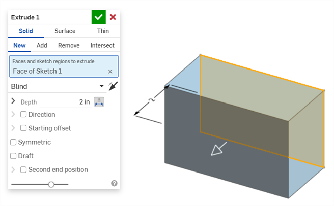
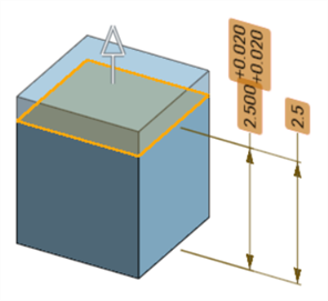
Dimensione profondità:
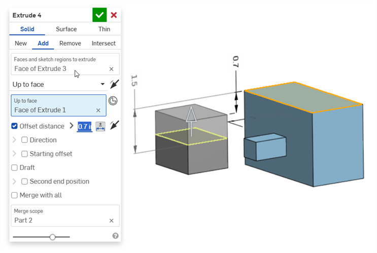
Dimensione distanza di offset (con una parte composita):
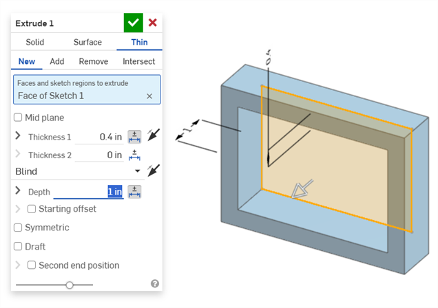
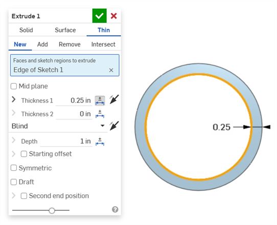
Estrusione sottile (quota di spessore 1 e profondità):
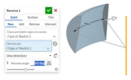
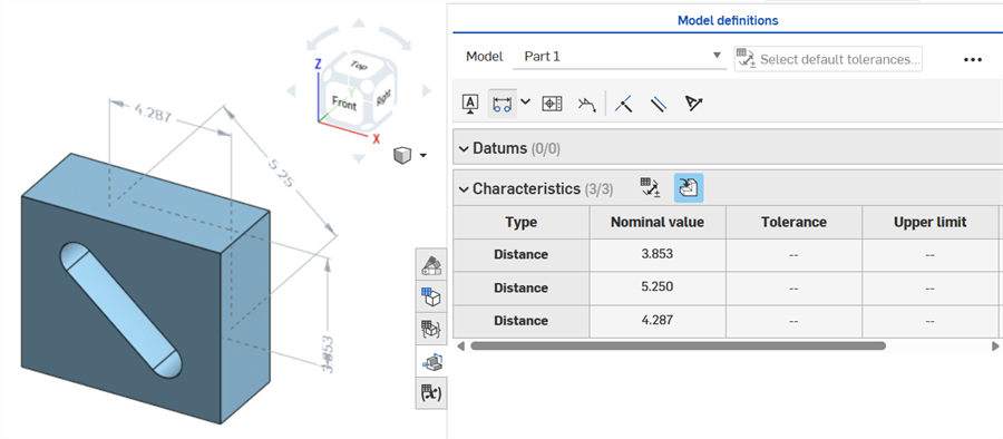
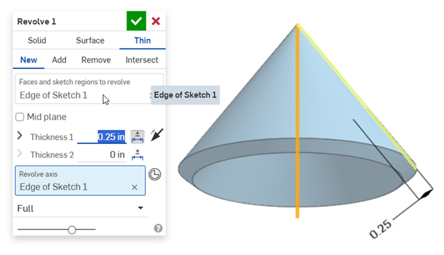
Rivoluzione (quota Angolo di rotazione):
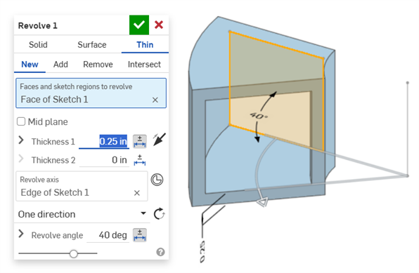
Rivoluzione (quote spessore 1 e Angolo di rotazione):
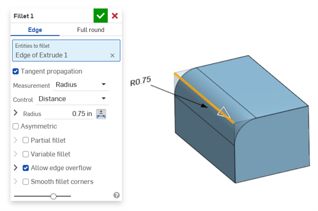
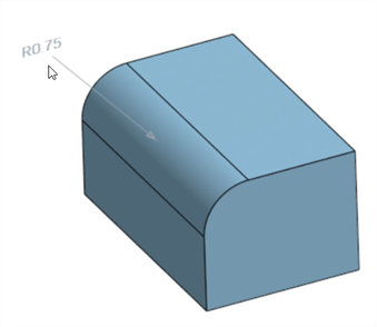
Raccordo (quota Raggio):
Creazione di una dimensione guidata del raccordo utilizzando lo strumento Quota raccordo della tabella di ispezione sulla barra degli strumenti di Annotazione:
Lo strumento Dimensione del pannello di ispezione (![]() ) utilizza sempre tolleranze predefinite lineari o angolari. Per impostare le dimensioni di una faccia con raccordo durante l'utilizzo, viene applicata come impostazione predefinita un tipo di tolleranza lineare. Per questo motivo, si consiglia di applicare le tolleranze del raccordo dalla finestra di dialogo della funzione Raccordo (per una dimensione guida) o di utilizzare Dimensione raccordo dal pannello di ispezione (per una dimensione guidata).
) utilizza sempre tolleranze predefinite lineari o angolari. Per impostare le dimensioni di una faccia con raccordo durante l'utilizzo, viene applicata come impostazione predefinita un tipo di tolleranza lineare. Per questo motivo, si consiglia di applicare le tolleranze del raccordo dalla finestra di dialogo della funzione Raccordo (per una dimensione guida) o di utilizzare Dimensione raccordo dal pannello di ispezione (per una dimensione guidata).
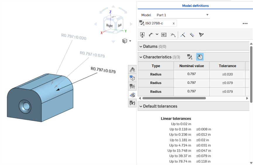
Dimensionamento di una faccia del raccordo - Annotata in senso orario: utilizzo dello strumento Dimensione (guidata; annotata in grigio), utilizzo dello strumento di dimensione del raccordo (guidata; annotata in grigio) e impostazione della tolleranza per il valore del raggio della funzione Raccordo (guida; annotata in nero). Tutte e 3 le dimensioni sono elencate nella tabella Caratteristiche.
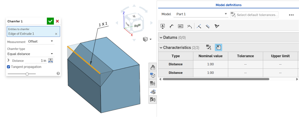
Uno Smusso è definito come distanza-angolo o distanza-distanza tra una faccia e un bordo. Le quote della larghezza dello Smusso sono specificate come la distanza da un bordo alla Virtual sharp. La visualizzazione delle virtual sharp viene aggiunta al bordo quotato, inclusa una curva tratteggiata.
-
Le tolleranze non vengono disabilitate quando si utilizza una misurazione tangente, poiché possono funzionare in determinati casi, soprattutto se si tiene conto della tolleranza specificata.
-
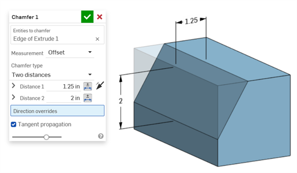
In situazioni in cui vengono utilizzate due misurazioni per lo smusso (due distanze o distanza e angolo), l'utente non deve creare tolleranze per entrambe. Se necessario le tolleranze possono essere aggiunte a un solo parametro.
Il tipo di smusso a distanza uguale mostra 2 valori di tolleranza distanza, che vengono riportati nella tabella, anche se nella finestra di dialogo è presente una sola opzione di tolleranza della distanza:
Esempio con due distanze:
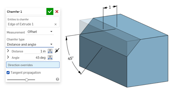
Esempio con distanza e angolo:
Per i casi in cui lo smusso produce una distanza variabile (ad esempio, se lo smusso viene applicato a una faccia del cilindro collegata perpendicolarmente a un altro cilindro), prova a selezionare la tangente per la misurazione, in modo da rendere la distanza uniforme lungo il bordo:
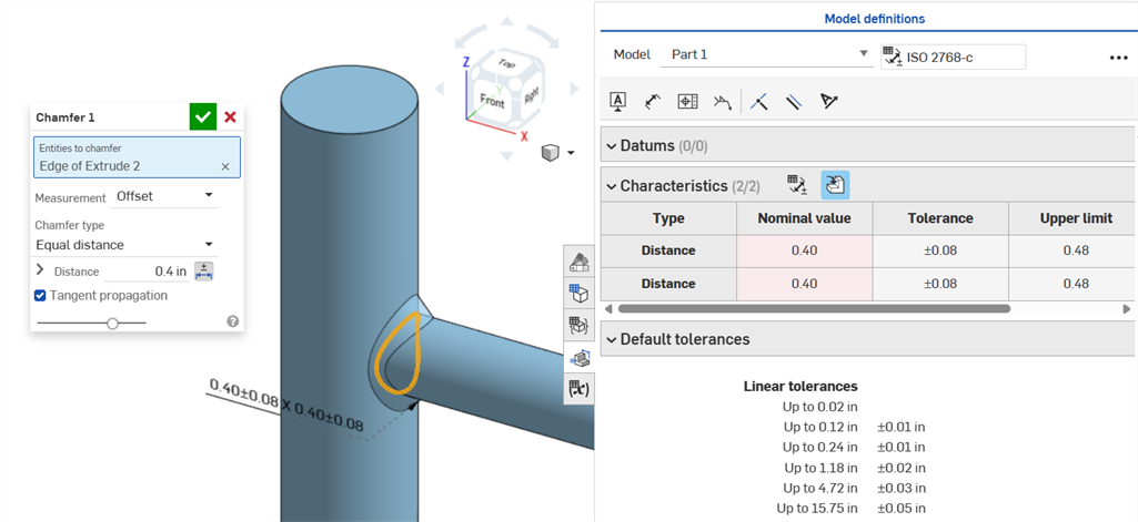
Uno smusso non uniforme che utilizza una misurazione dell'offset e mostra un errore di Valore nominale.
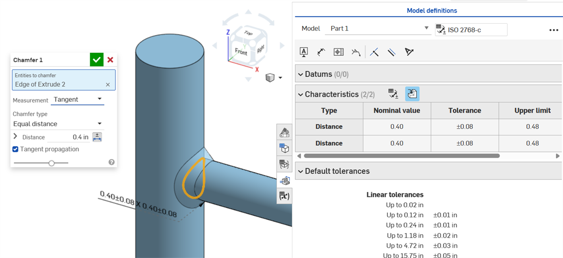
Uno smusso uniforme che utilizza una misurazione tangente determina un Valore nominale senza errori.
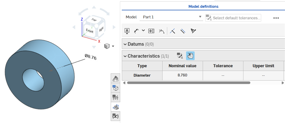
Se una tolleranza viene applicata su una funzione foro, può essere visualizzata nella Tabella di ispezione.
Considerazioni da tenere a mente:
-
Le quote dei fori sono visibili solo come righe nella Tabella di ispezione. Non vengono inserite quote nell'area grafica. Questo serve a non ingombrare l'area grafica con troppe didascalie.
-
Affinché che le quote dei fori siano visibili nella Tabella di ispezione, è necessario inserire prima un'altra didascalia sulla parte (ad esempio un riferimento).
-
Viene mostrato un unico un set di quote (diametro, distanza e/o angolo) per funzione del foro. I fori in ripetizione o aggiuntivi appartenenti alla stessa funzione non vengono quotati separatamente.
-
La quota personalizzata di Inclina angolo non è attualmente supportata e non crea una riga nella Tabella di ispezione.
-
L'evidenziazione incrociata funziona come segue:
-
La distanza (profondità) non viene evidenziata in modo incrociato perché non sono presenti facce a nessuna delle due estremità del foro e i bordi non sono attualmente supportati per MBD.
-
Il diametro, la distanza (profondità lamatura) e l'angolo (angolo svasatura) evidenziano una singola faccia.
-
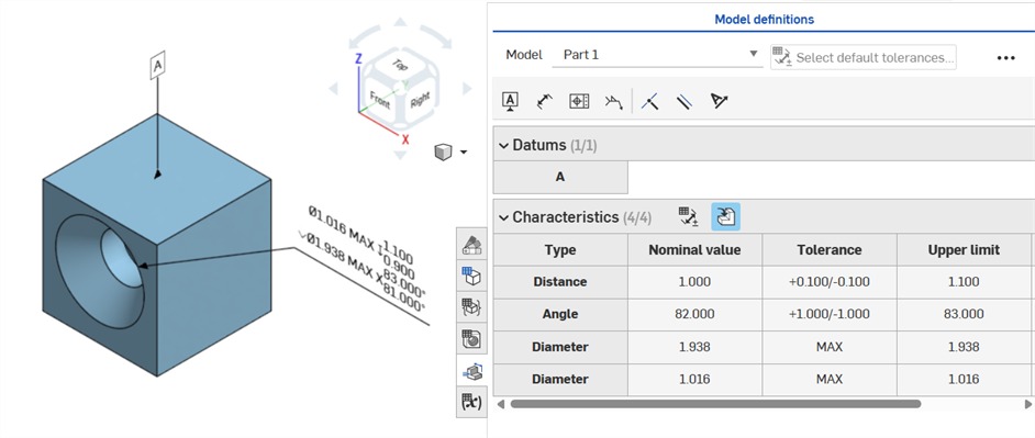
Le quote dei fori diventano visibili nella Tabella di ispezione dopo che è stato aggiunto un Riferimento a una delle facce della parte.
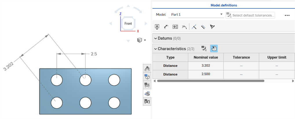
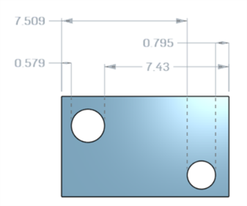
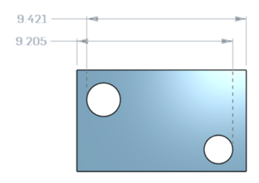
Quote di distanza tra gli assi tra i cerchi concentrici utilizzando lo strumento Quota (![]() ):
):
Quote minime orizzontali, diagonali e verticali tra due facce cilindriche utilizzando lo strumento Quota minima (![]() ):
):
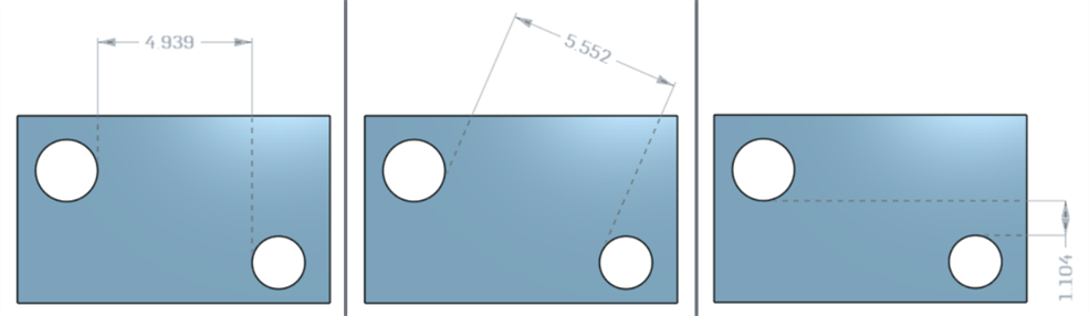
Quote minime tra cilindri e bordi:
Una quota diagonale minima aggiunta in uno schizzo (a sinistra) viene visualizzata nella tabella Caratteristiche una volta creata la parte (a destra):
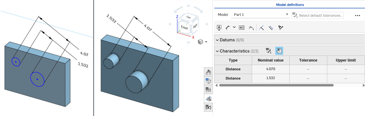
Le quote minime orizzontali e verticali non possono attualmente essere create in uno schizzo.
Quote minime orizzontali, diagonali e verticali tra due facce cilindriche utilizzando lo strumento Quota massima (![]() ):
):
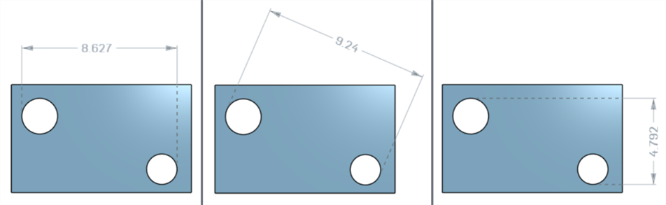
Quote massime tra cilindri e bordi:
Quote massime orizzontali, diagonali e verticali tra le facce ad arco di un'asola:
La quota diagonale massima aggiunta in uno schizzo (a sinistra) viene visualizzata nella tabella Caratteristiche una volta creata la parte (a destra):
Le quote massime orizzontali e verticali non possono attualmente essere create in uno schizzo.
Lo spessore viene visualizzato nella Tabella di ispezione come una riga di tipo Distanza.
Estrusione sottile (quota Spessore 1):
Rotazione sottile (quota Spessore 1):
Dimensione linea di mezzeria di uno schizzo con tolleranza abilitata:
Se la linea di mezzeria è utilizzata come asse attorno al quale ruotare la geometria dello schizzo, è visualizzata come dimensione del Diametro quando si apre la Tabella di ispezione:
Quando si aggiungono annotazioni, si apportano modifiche al modello e si applicano gli aggiornamenti delle funzioni, Onshape tenta automaticamente di convalidare i dati MBD associati.
Le convalide sono effettuate su base individuale e per singola parte; pertanto, le annotazioni devono fare riferimento alla geometria della stessa parte o parte composita.
Quando una caratteristica è invalidata, sia l'annotazione che la caratteristica corrispondente nella Tabella di ispezione sono visualizzate in rosso.
Le caratteristiche non valide si dividono in due categorie: riferimenti mancanti e valori non corrispondenti.
Un riferimento mancante si verifica quando la geometria utilizzata per definire una caratteristica non esiste più o è cambiata in modo da interrompere l'associazione. Ciò può derivare da una funzione eliminata, da una sostituzione della faccia o da un'altra modifica topologica.
Una mancata corrispondenza del valore si verifica quando il valore della geometria di riferimento non corrisponde più alla tolleranza definita. Ciò può verificarsi, ad esempio, quando il diametro di un foro è aumentato oltre i limiti specificati.
Risolvi le caratteristiche non valide valutando le cause potenziali.
Quando usi Confronta, seleziona le facce per visualizzarne le annotazioni, tolleranze e caratteristiche associate.
Convalida e risolvi gli errori modificando l'elenco Funzioni e le annotazioni MBD.
Gli errori MBD non creano annotazioni o voci di riga nella Tabella di ispezione, a meno che non venga apportata una modifica al modello che invalida una voce di riga di annotazione esistente.
Gli errori sono visualizzati in rosso, analogamente agli altri errori di Onshape:
Errore generato durante l'estrusione da o verso un solido. L'annotazione non genera una voce di riga nella Tabella di ispezione.
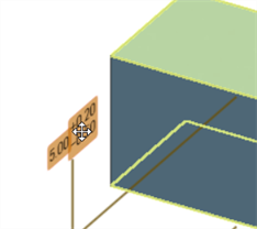
Se la geometria viene modificata in modo da invalidare un'annotazione specifica, l'annotazione corrispondente è indicata in rosso nell'area grafica ed evidenziata in rosso nella Tabella di ispezione, segnalando un errore. Ad esempio, la faccia superiore del rettangolo è stata spostata di 0,5 pollici, comportando una differenza del valore misurato (3,5 pollici) rispetto al valore specificato (3,0 pollici):
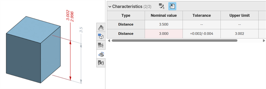
Esempi di errore
-
Riferimento mancante per questa annotazione: si verifica quando manca un riferimento. Ad esempio, la parte A viene estrusa fino alla faccia della parte B e viene aggiunta una tolleranza alla distanza di offset dell'estrusione della parte A.
-
Entrambe le facce devono appartenere alla stessa parte: le definizioni del modello sono valide solo su base individuale per singola parte. Ad esempio, non puoi quotare la distanza tra una faccia della Parte A e una faccia della Parte B.
-
Le annotazioni MBD devono essere sempre associate a delle facce. Al momento non è possibile fare riferimento a bordi e vertici.
-
Le definizioni dei modelli sono valide su base individuale per singola parte. Anche le parti composite sono valide. Ad esempio, puoi quotare la distanza tra 2 facce della Parte A o 2 facce d Parte B, ma non tra una faccia nella Parte A e una faccia nella Parte B. Per farlo, crea prima una Parte C composita unendo si Parte A che la Parte B. A questo punto puoi quotare la distanza tra queste 2 facce.
-
Passando con il mouse sopra la riga Tipo nella Tabella di ispezione, viene evidenziata la quota corrispondente nell'area grafica.
-
Durante la modifica della geometria di una parte, tutte le definizioni del modello associate vengono evidenziate in arancione:
-
Se una parte o un Part Studio vengono derivati tramite la funzione Entità derivate, tutte le definizioni del modello sono in sola lettura e non possono essere modificate. Puoi ancora spostare le annotazioni e le quote guidate continuano ad aggiornarsi se la geometria derivata viene modificata; tuttavia, le definizioni del modello sottostante possono essere regolate solo in un Part Studio di origine e quindi aggiornate nella Funzione derivata. Per ulteriori informazioni, consulta Entità derivate.
-
È possibile aggiungere commenti ed etichette alle quote di tolleranza dello schizzo, dimensioni delle funzioni, didascalie foro e annotazioni della tabella di ispezione (quote, riferimenti, tolleranze geometriche) nell'area grafica. Per ulteriori informazioni, consulta Aggiungere commenti alle annotazioni MBD.