 Corte de esquina de chapa metálica
![]()
![]()
![]()
Corte la esquina de las piezas de chapa existentes aplicando un redondeo o un chaflán. Seleccione una arista o un vértice de la esquina y especifique el tipo de Corte de esquina y la distancia. Se recomienda utilizar esta operación una vez finalizadas todas las bridas y juntas del modelo de chapa metálica.
Uno de los pasos finales en el diseño de chapa metálica consiste en cortar las esquinas puntiagudas para evitar lesiones y enganches. La operación de corte de esquina de chapa metálica de Onshape lo consigue al agregar un empalme o un chaflán a cualquier esquina seleccionada.
Reserve los cortes de esquina para las operaciones finales de una pieza de chapa metálica. Una vez que se aplica una operación de corte de esquina, el tipo y el estilo de unión no se pueden modificar.
Los cortes de esquina se aplican a cualquier esquina de una pieza de chapa metálica, incluso a las creadas debido a cortes de liberación de pliegue.
Inicie una nueva operación Corte de esquina. Seleccione la pestaña Empalme o Chaflán y, a continuación, seleccione una o más aristas o vértices de las esquinas de una pieza de chapa metálica. Las esquinas se pueden seleccionar en estado formado o aplanado.
Para un redondeo, seleccione el radio o el ancho para la medida. Además, defina la opción de control del redondeo en Distancia, Cónico o Curvatura.
Defina el valor del radio o el ancho para acotar el empalme. Para un empalme de base cónica, defina el valor Rho. Para un empalme basado en curvatura, defina la Magnitud.
Para un redondeo que consiste en la fusión de dos radios, seleccione Asimétrico e ingrese el segundo radio. Alterne las flechas de volteo asimétrico cuando sea necesario.
Tanto Distancia como Cónico tienen la opción Permitir desbordamiento de aristas. Al marcar esta opción, la operación de empalme puede modificar las aristas de la cara creada mediante el empalme, lo que genera una superficie lisa y continua. Si no marca esta opción, Onshape conserva las aristas de la cara redondeada.
Para un Chaflán, defina la medida en Desfase o Tangente. A continuación, seleccione un tipo de Chaflán. La misma distancia extiende el chaflán a una distancia igual desde la arista en ambas direcciones. Dos distancias extienden el chaflán por cada valor de distancia introducido. La distancia y el ángulo extienden el chaflán una distancia especificada en una dirección y un ángulo específico en la otra. Con ambas opciones, puede alternar la flecha de dirección opuesta para cambiar de lado.
Para crear un corte de esquina redondeado en un modelo de chapa metálica, haga lo siguiente:
- Cuando esté en un Part Studio con un modelo de chapa metálica existente, haga clic en Corte de esquina (
 ).
). 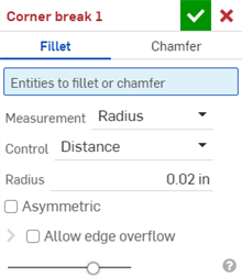
- Seleccione Redondeo para el tipo de corte de esquina.
- Seleccione una arista o un vértice de esquina en el modelo de chapa metálica del área gráfica. También se puede seleccionar una arista o un vértice de esquina en la sección de vista plana del modelo de chapa metálica y la vista plana.
- Seleccione el tipo de medición, que puede ser alguna de las siguientes opciones:
- Radio: especifique la medida radial del redondeo.
- Ancho: especifique la distancia entre los dos extremos del redondeo (un ancho constante).
- Seleccione un tipo de control:
- Distancia: el redondeo tiene una arista circular con el valor de radio ingresado. Onshape recuerda este valor cuando se crean redondeos nuevos.
- Cónica: el redondeo tiene una arista cónica con el valor de radio que ha introducido y, de manera opcional, un valor Rho para definir el estilo del redondeo:

Valores Rho: 0,25 (izquierda; curva elíptica): 0,5 (centro; curva parabólica); 0,999 (derecha; curva hiperbólica: ampliada)
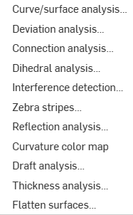
- Curvatura: el redondeo hace coincidir la curvatura de las aristas circundantes con el valor de radio ingresado y, opcionalmente, con un valor de magnitud de entre 0 y 0,999 para modificar la tangencia. Active la opción Rayas de cebra (desde el menú Mostrar herramientas de análisis) para ver la tangencia con mayor claridad:
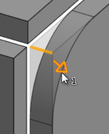
Al ingresar un valor de radio, también puede utilizar el manipulador de arrastre, como se indica en la imagen siguiente mediante una flecha, para visualizar el redondeo y acercarse a un valor estimado:
Onshape recuerda la selección de tipo y valor de medida y abre el cuadro de diálogo con la última opción seleccionada en operaciones posteriores.
- Active la opción Asimétrico e ingrese un segundo radio para tener un valor de radio de arista del redondeo diferente en un extremo del arista redondeada. Haga clic en la flecha Voltear asimetría para utilizar el otro extremo del redondeo como segunda arista redondeada (asimétrica).
- De forma predeterminada, la opción Permitir desbordamiento de aristas está desactivada. Active la opción para permitir que las aristas tangentes se eliminen de la superficie de redondeo, si es necesario. Las aristas que se generan de forma predeterminada restringen estrictamente la dirección del redondeo a lo largo de las aristas del redondeo. Cuando la opción Permitir desbordamiento de aristas está activada, el redondeo puede modificar las aristas de la cara que crea el redondeo para crear una superficie lisa y continua. Si la opción no está activada, se conservan las aristas de la cara redondeada, lo que hace que la pieza fluya con más libertad.
Haga clic en el menú desplegable Permitir desbordamiento de aristas para abrir un campo en el que puede seleccionar las aristas que quiere conservar.
- Haga clic en la marca de verificación (
 ) para aceptar la nueva operación Corte de esquina.
Para crear un corte de esquina achaflanado en un modelo de chapa metálica, haga lo siguiente:
- Cuando esté en un Part Studio con un modelo de chapa metálica existente, haga clic en Corte de esquina (
 ).
). 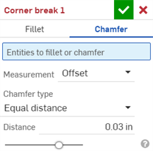
- Seleccione Chaflán para el tipo de corte de esquina.
- Seleccione una arista o un vértice de esquina en el modelo de chapa metálica del área gráfica. También se puede seleccionar una arista o un vértice de esquina en la sección de vista plana del modelo de chapa metálica y la vista plana.
- Seleccione el tipo de medición, que puede ser alguna de las siguientes opciones:
- Desfase: establece la distancia ingresada en el campo Distancia desde la arista inicial hasta el chaflán. Esta opción depende de la arista; el cálculo comienza en la primera selección y, luego, avanza a lo largo de la cadena .
- Tangente: establece la distancia ingresada en el campo Distancia desde la intersección de la tangente de las dos caras adyacentes al chaflán. Esta opción NO depende de la arista.
- Seleccione un tipo de chaflán:
- Distancia igual: el chaflán se extenderá a una distancia igual desde el borde en ambas direcciones.
- Dos distancias: el chaflán se extenderá a diferentes distancias en cada dirección.
- Distancia y ángulo - El chaflán extenderá la distancia especificada en una dirección y el ángulo especificado en la otra.
Onshape recuerda la selección del tipo de chaflán y abre el cuadro de diálogo con la última opción seleccionada en operaciones posteriores.
- Ingrese las distancias del chaflán. El valor predeterminado de Onshape es de 45 grados para el ángulo, pero este recuerda el último valor de distancia ingresado para los chaflanes de Distancia equivalente y Distancia y ángulo.
- Si seleccionó Dos distancias o Distancia y ángulo, haga clic en el botón de flecha para voltear la dirección de todas las aristas o especifique las aristas individuales para voltearlas en el campo Invalidaciones de dirección.
- Haga clic en la marca de verificación (
 ) para aceptar la nueva operación Corte de esquina.
-
Tras aplicar una operación de corte de esquina, el tipo (desgarro o pliegue) y el estilo (Junta de arista o Junta plana) de todas las juntas del modelo ya no se pueden editar en la Vista plana y de tabla de chapa metálica. Se recomienda agregar cualquier operación de Corte de esquina después de finalizar todas las ediciones de las bridas y juntas del modelo de chapa metálica.
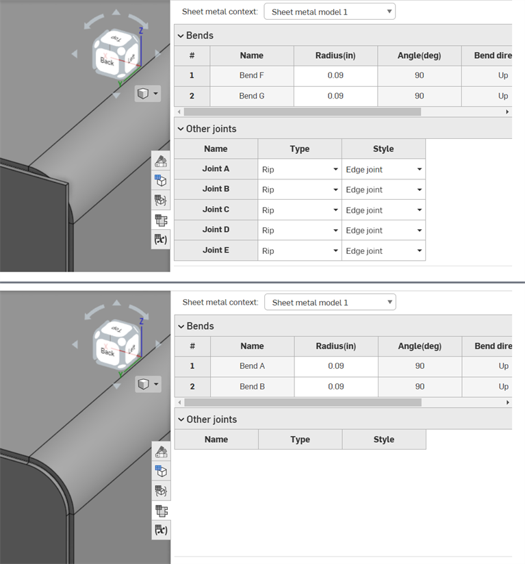
Antes de aplicar la operación Corte de esquina (arriba); después de aplicar la operación Corte de esquina (abajo)
-
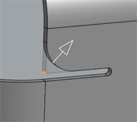
Puede utilizar la operación Corte de esquina para aplicar redondeos o chaflanes a aristas y vértices de liberación de pliegue, además de a las esquinas:
-
No se pueden agregar varios redondeos, chaflanes ni una combinación de ambos a las esquinas en las que se aplica una sola operación Corte de esquina. Cree una operación Corte de esquina adicional para agregar un redondeo o chaflán adicional a cualquier vértice o arista de una operación Corte de esquina existente:
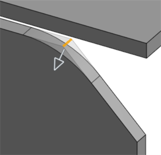
Redondeo aplicado a una arista achaflanada mediante una segunda operación de Corte de esquina
Cuando un modelo de chapa metálica está activo (en el proceso de creación o edición), hay herramientas adicionales disponibles:
-
 Brida: cree una pared para cada arista seleccionada, conectada a la arista seleccionada con un pliegue.
 -
 Dobladillo: cree un dobladillo para cada arista o cara seleccionada en una pieza de chapa metálica existente.
 -
 Pestaña: añada una pestaña a una brida de chapa metálica.
 -
 Pliegue: pliegue un modelo de chapa metálica a lo largo de una línea de referencia, con opciones de control de pliegue adicionales.
 -
 Forma: crea operaciones de formas en modelos de chapa metálica existentes. Las formas se pueden seleccionar del documento actual, de otros documentos o de una biblioteca predefinida de formas de chapa metálica.
 -
 Loft - Create sheet metal models that connect two profiles.
 -
 Crear unión: convierta la intersección de dos paredes en una operación de unión, ya sea un pliegue (paredes unidas por una geometría cilíndrica) o una rasgadura (pequeño espacio entre dos paredes).
 -
 Esquina: modifique el tipo de esquina y la escala de liberación.
 -
 Liberación de pliegue: modifique una liberación de pliegue (el pequeño corte que se hace donde el extremo del pliegue se une al pliegue libre), la profundidad y el ancho de liberación.
 -
 Modificar unión: realice cambios en una unión existente, como convertir un pliegue en una rasgadura. Disponible actualmente a través de la tabla de vista plana.
 -
 Corte de esquina: corta la esquina de las piezas de chapa metálica existentes aplicando un redondeo o un chaflán. Seleccione el vértice o la arista de una esquina y especifique el tipo de Corte de esquina y la distancia. Se recomienda utilizar esta operación una vez finalizadas todas las bridas y juntas del modelo de chapa metálica.
 -
 Tabla de chapa metálica y vista plana: abra y cierre las tablas Rasgadura/Pliegue y visualice el patrón plano del modelo de chapa metálica. Utilice esta tabla para convertir rasgaduras en pliegues y viceversa.
 -
 Acabar modelo de chapa metálica: cierra (desactiva) el modelo de chapa metálica y crea una operación en la lista de operaciones.
Para crear un corte de esquina redondeado en un modelo de chapa metálica, haga lo siguiente:
- Cuando esté en un Part Studio con un modelo de chapa metálica existente, toque Corte de esquina (
 ).
). 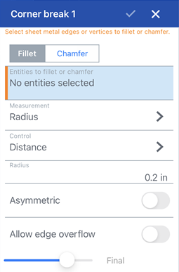
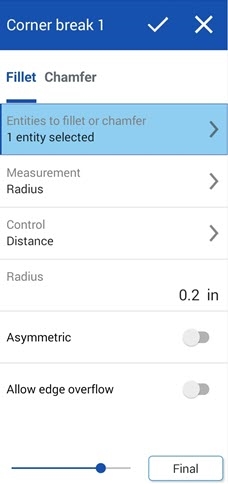
Corte de esquina: cuadro de diálogo Redondeo para iOS (primera imagen de arriba) y para Android (segunda imagen de arriba)
- Toque Redondeo para el tipo de corte de esquina.
- Seleccione una arista o un vértice de esquina en el modelo de chapa metálica del área gráfica.
- Seleccione el tipo de medición, que puede ser alguna de las siguientes opciones:
- Radio: especifique la medida radial del redondeo.
- Ancho: especifique la distancia entre los dos extremos del redondeo (un ancho constante).
- Seleccione un tipo de control:
- Distancia: el redondeo tiene una arista circular con el valor de radio ingresado. Onshape recuerda este valor cuando se crean redondeos nuevos.
- Cónica: el redondeo tiene una arista cónica con el valor de radio que ha introducido y, de manera opcional, un valor Rho para definir el estilo del redondeo:

Rho values: 0.25 (left; elliptical curve); 0.5 (middle; parabolic curve); 0.999 (right; hyperbolic curve - zoomed in)
- Curvatura: el redondeo hace coincidir la curvatura de las aristas circundantes con el valor de radio que usted ingresa y, opcionalmente, con un valor de magnitud de entre 0 y 0,999 para ajustar la tangencia.
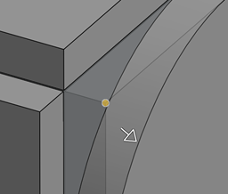
Al ingresar un valor de radio, también puede utilizar el manipulador de arrastre, como se indica en la imagen siguiente mediante una flecha, para visualizar el redondeo y acercarse a un valor estimado:
- Active la opción Asimétrico e ingrese un segundo radio para tener un valor de radio de arista del redondeo diferente en un extremo del arista redondeada. Haga clic en la flecha Voltear asimetría para utilizar el otro extremo del redondeo como segunda arista redondeada (asimétrica).
- De forma predeterminada, la opción Permitir desbordamiento de aristas está desactivada. Active esta opción para permitir que las aristas tangentes se «borren» de la superficie de redondeo, si es necesario. Las aristas que se generan de forma predeterminada restringen estrictamente la dirección del redondeo a lo largo de las aristas del redondeo. Cuando la opción Permitir desbordamiento de aristas está habilitada, el redondeo puede modificar las aristas de la cara que crea el redondeo para crear una superficie lisa y continua. Cuando la opción está desactivada, se conservan las aristas de la cara redondeada, lo que hace que la pieza fluya con más libertad.
Toque el campo Aristas para conservar y seleccione las aristas que quiere conservar en el área gráfica.
- Toque la marca de verificación para aceptar la nueva operación Corte de esquina.
Para crear un corte de esquina achaflanado en un modelo de chapa metálica, haga lo siguiente:
- Cuando esté en un Part Studio con un modelo de chapa metálica existente, toque Corte de esquina (
 ).
). 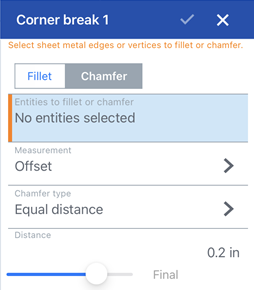
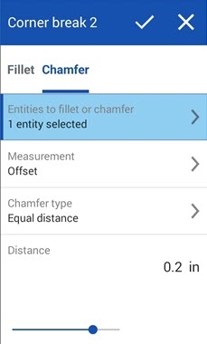
Corte de esquina: cuadro de diálogo Chaflán para iOS (primera imagen de arriba) y para Android (segunda imagen de arriba)
- Toque Chaflán para el tipo de corte de esquina.
- Seleccione una arista o un vértice de esquina en el modelo de chapa metálica del área gráfica.
- Seleccione el tipo de medición, que puede ser alguna de las siguientes opciones:
- Desfase: establece la distancia ingresada en el campo Distancia desde la arista inicial hasta el chaflán. Esta opción depende de la arista; el cálculo comienza en la primera selección y, luego, avanza a lo largo de la cadena .
- Tangente: establece la distancia ingresada en el campo Distancia desde la intersección de la tangente de las dos caras adyacentes al chaflán. Esta opción NO depende de la arista.
- Seleccione un tipo de chaflán:
- Distancia igual: el chaflán se extenderá a una distancia igual desde el borde en ambas direcciones.
- Dos distancias: el chaflán se extenderá a diferentes distancias en cada dirección.
- Distancia y ángulo - El chaflán extenderá la distancia especificada en una dirección y el ángulo especificado en la otra.
- Ingrese las distancias del chaflán. El valor predeterminado de Onshape es de 45 grados para el ángulo, pero este recuerda el último valor de distancia ingresado para los chaflanes de Distancia equivalente y Distancia y ángulo.
- Si seleccionó Dos distancias o Distancia y ángulo, toque el botón de flecha para voltear la dirección de todas las aristas o especifique las aristas individuales para voltearlas en el campo Invalidaciones de dirección.
- Toque la marca de verificación para aceptar la nueva operación Corte de esquina.
-
Tras aplicar una operación de corte de esquina, el tipo (desgarro o pliegue) y el estilo (Junta de arista o Junta plana) de todas las juntas del modelo ya no se pueden editar en la Vista plana y de tabla de chapa metálica. Se recomienda agregar cualquier operación de Corte de esquina después de finalizar todas las ediciones de las bridas y juntas del modelo de chapa metálica.
-
Puede utilizar la operación Corte de esquina para aplicar redondeos o chaflanes a aristas y vértices de liberación de pliegue, además de a las esquinas:

-
No se pueden agregar varios redondeos, chaflanes ni una combinación de ambos a las esquinas en las que se aplica una sola operación Corte de esquina. Cree una operación Corte de esquina adicional para agregar un redondeo o chaflán adicional a cualquier vértice o arista de una operación Corte de esquina existente:

Redondeo aplicado a una arista achaflanada mediante una segunda operación de Corte de esquina
Cuando un modelo de chapa metálica está activo (en el proceso de creación o edición), hay herramientas adicionales disponibles:
-
 Brida: cree una pared para cada arista seleccionada, conectada a la arista seleccionada con un pliegue.
 -
 Pestaña: añada una pestaña a una brida de chapa metálica.
 -
 Crear unión: convierta la intersección de dos paredes en una operación de unión, ya sea un pliegue (paredes unidas por una geometría cilíndrica) o una rasgadura (pequeño espacio entre dos paredes).
 -
 Esquina: modifique el tipo de esquina y la escala de liberación.
 -
 Liberación de pliegue: modifique una liberación de pliegue (el pequeño corte que se hace donde el extremo del pliegue se une al pliegue libre), la profundidad y el ancho de liberación.
 -
 Loft - View and modify sheet metal models that connect two profiles.
 -
 Corte de esquina: corta la esquina de las piezas de chapa metálica existentes aplicando un redondeo o un chaflán. Seleccione el vértice o la arista de una esquina y especifique el tipo de Corte de esquina y la distancia. Se recomienda utilizar esta operación una vez finalizadas todas las bridas y juntas del modelo de chapa metálica.
 -
 Acabar modelo de chapa metálica: cierra (desactiva) el modelo de chapa metálica y crea una operación en la lista de operaciones.