Definición basada en modelo (MBD)
![]()
![]()
![]()
Disponible en: elemento Part Studio, ensamblaje
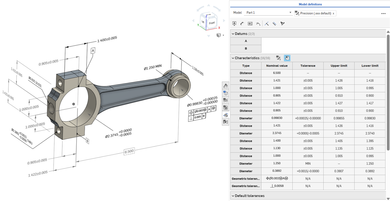
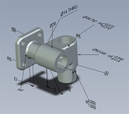
La definición basada en modelo (MBD) se refiere al proceso de acotar y anotar el modelo en el elemento Part Studio de modo que este contenga todos los datos necesarios para definir un producto. Con la MBD, el modelo se convierte en la autoridad de origen que impulsa todas las actividades de ingeniería. Además, los proveedores y las organizaciones pueden utilizar este modelo en etapas posteriores.
Los datos de MBD funcionan junto con Opciones de tolerancia, donde las cotas del boceto y de las operaciones se hacen tolerantes, y Tabla de inspección, donde los datos de MBD se pueden ver, añadir y exportar para cada pieza en un elemento Part Studio.
La MBD no pretende reemplazar los dibujos. su objetivo es capturar y ampliar la información de fabricación de productos (PMI) y la información empresarial basada en modelo (MBE) de un modelo para un uso posterior adicional o alternativo.
Algunas características de la MBD:
-
Metadatos de cotas y anotaciones incrustados en el modelo del elemento Part Studio.
-
Mejora de la colaboración en tiempo real en el modelo del elemento Part Studio.
-
Una única fuente de información fiable para ingenieros de toda la organización.
-
Vínculo a procesos posteriores, como la inspección de máquinas de medición por coordenadas (CMM).
Las cotas de referencia del boceto y las operaciones MBD se pueden editar directamente en el área gráfica.
La información de fabricación del producto se puede editar en el área gráfica cuando la tabla de inspección está abierta, así como en los bocetos y las operaciones en los que se definieron originalmente.
Para editar las tolerancias, haga doble clic en la cota en el área gráfica. Si la cota hace referencia a la lista de operaciones, Onshape abre el boceto o la operación para editarlo. Si la cota se creó con la barra de herramientas de anotaciones, edítela desde el área gráfica. A medida que cambian el modelo y las tolerancias, la tabla de inspección se actualiza en tiempo real.
En la tabla de características, filtre las filas con dos botones de alternancia. Al principio, se muestran las anotaciones con las tolerancias predeterminadas aplicadas y las anotaciones de la geometría derivada se ocultan. Las anotaciones derivadas solo se pueden actualizar si se modifica el origen.
Utilice el resaltado cruzado para identificar y localizar rápidamente las referencias de modelo asociadas. Pase el ratón por encima de las celdas de la tabla de inspección para aplicar el resaltado cruzado a la pieza, las caras, las operaciones y las anotaciones asociadas a la referencia en el área gráfica. Seleccione una anotación en el área gráfica o haga clic en una celda de referencia o tipo para mantener visible el resaltado.
Para eliminar una anotación, selecciónela en el área gráfica y pulse en Borrar. Al borrar una anotación que hace referencia a la lista de operaciones, se eliminan las opciones de tolerancia de la cota del boceto o del valor de la entidad, y se elimina la fila de la tabla de características. Al borrar una anotación colocada con la barra de herramientas de anotaciones, se elimina de la tabla. Las anotaciones derivadas no se pueden borrar.
-
Abra el panel de inspección (
 ) para mostrar las cotas de MBD en las áreas gráficas (imagen de la izquierda a continuación).
 -
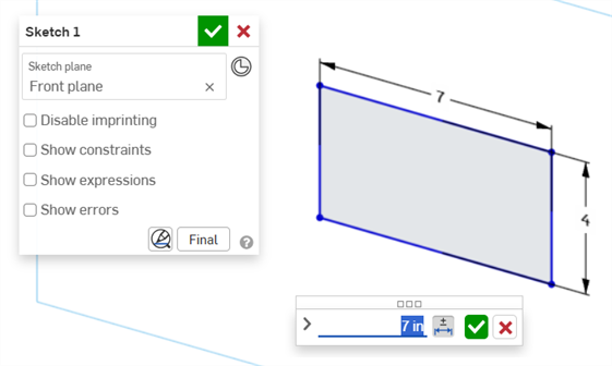
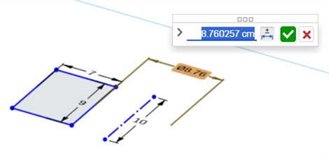
Haga doble clic en la cota de referencia asociada a un boceto (imagen de la derecha a continuación):
Se abre el cuadro de diálogo Contexto de cota con el contexto colocado en el valor de la cota. Al mismo tiempo, se abre el cuadro de diálogo Boceto:
-
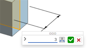
Con el teclado, introduzca un valor numérico o utilice las flechas arriba/abajo para incrementar el valor en el cuadro de diálogo Contexto de cota. A medida que se ajusta este valor, el boceto se actualiza de forma dinámica.
Si se introduce un valor numérico, pulse la tecla Tabulador para ver la actualización del valor del boceto.
-
Pulse Entrar en el teclado o haga clic en la marca de verificación (
 ) del cuadro de diálogo Contexto de cota para cerrar este cuadro de diálogo:
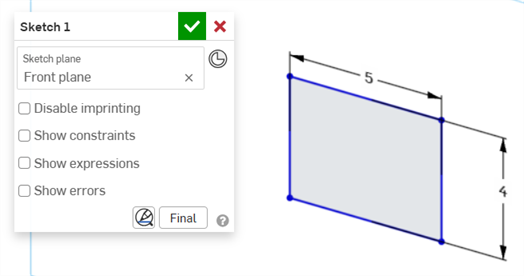
-
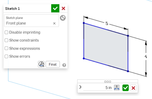
Pulse la marca de verificación (
) del cuadro de diálogo Boceto para aceptar el nuevo valor de boceto.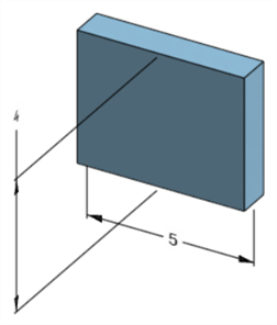
La cota del boceto editada que ajusta la cota del modelo
-
Abra el panel de inspección (
) para mostrar las cotas de MBD en las áreas gráficas (imagen de la izquierda a continuación). -
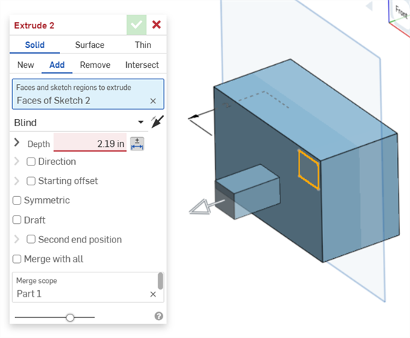
Haga doble clic en la cota de referencia asociada a una operación (imagen de la derecha a continuación):
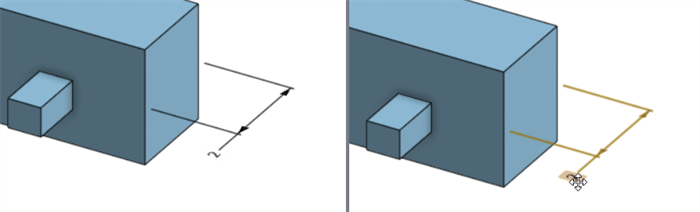
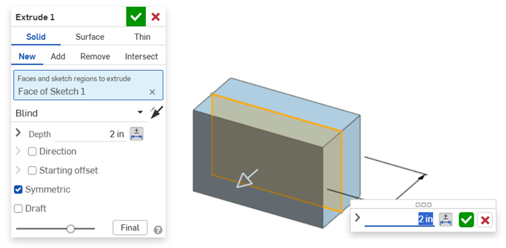
Se abre el cuadro de diálogo Contexto de cota con el contexto colocado en el valor de cota. Al mismo tiempo, se abre el cuadro de diálogo Operaciones asociado (Extruir en este ejemplo):
-
Con el teclado, introduzca un valor numérico o utilice las flechas arriba/abajo para incrementar el valor en el cuadro de diálogo Contexto de cota. A medida que se ajusta este valor, tanto el modelo como el valor del cuadro de diálogo Operaciones se actualizan de forma dinámica.
Si se introduce un valor numéricamente, pulse la tecla Tabulador para ver la actualización del valor en el cuadro de diálogo Operaciones.
-
Pulse Entrar en el teclado o haga clic en la marca de verificación (
) del cuadro de diálogo Cotexto de cota para cerrar este cuadro de diálogo: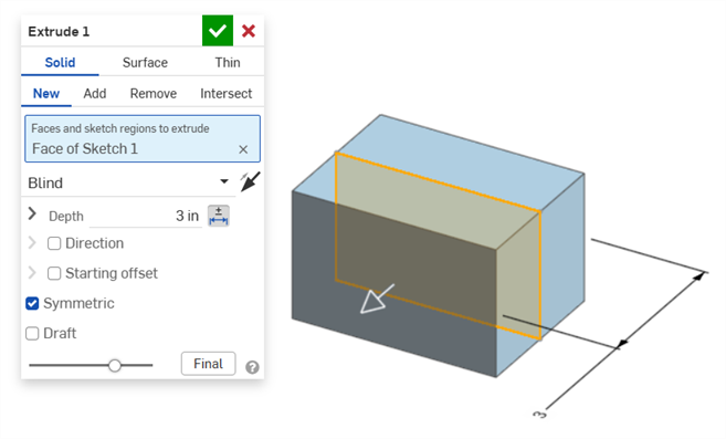
-
Vuelva a pulsar Entrar en el teclado o haga clic en la marca de verificación del cuadro de diálogo Operaciones (
) para cerrar este cuadro de diálogo: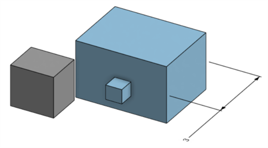
La cota de la operación modificada que ajusta la cota del modelo
Para borrar una anotación:
-
Seleccione la anotación en el área gráfica:
-
Presione la tecla Suprimir.
-
La anotación se borra del área gráfica y de la tabla de inspección.
Si la anotación es una cota de boceto u operación:
-
Se borran los valores de Opciones de tolerancia de la cota.
-
El ícono de opciones de tolerancia (
 ) se deselecciona.
 -
El valor de cota del cuadro de diálogo Boceto u Operación no se borra.
-
Las anotaciones no se pueden borrar en los siguientes casos:
-
La anotación es derivada.
-
La anotación se crea en una operación personalizada en la que el parámetro se convierte en tolerante, pero la opción de tolerancia no está disponible para la entrada del usuario.
En cualquier caso, aparece el siguiente mensaje:

-
Las cotas de conducción no se pueden editar. Al hacer doble clic en una cota de conducción, se abre el cuadro de diálogo Contexto de cota, pero sus valores no se pueden editar.
-
Las cotas derivadas no se pueden editar. Al hacer doble clic en una dimensión de referencia o de conducción a partir de una pieza derivada, no se abre el cuadro de diálogo Contexto de cota.
-
Para cancelar los cambios y salir del cuadro de diálogo Contexto de cota, pulse la tecla Esc. Si está editando una cota de operación, el cuadro de diálogo Contexto de cota y el cuadro de diálogo Operación se cierran simultáneamente. Si está editando una cota de boceto, solo se cierra el cuadro de diálogo Contexto de cota. El cuadro de diálogo Boceto se debe cerrar manualmente (haciendo clic en el ícono de la X).
-
Como alternativa, con el cuadro de diálogo Operación y el cuadro de diálogo Contexto de cota abiertos, el valor del primero se puede seleccionar y editar, lo que actualiza el cuadro de diálogo Contexto de cota y el modelo de forma dinámica. Una vez editado aquí, al pulsar Entrar, se cierran simultáneamente el cuadro de diálogo Operaciones y el cuadro de diálogo Contexto de cota.
-
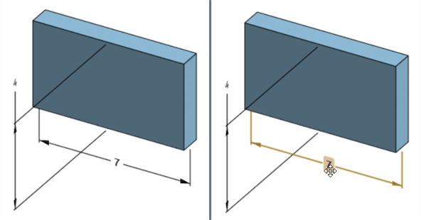
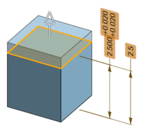
La ubicación de la cota del modelo y la ubicación de su cota de boceto correspondiente no están bloqueadas entre sí. Son independientes:
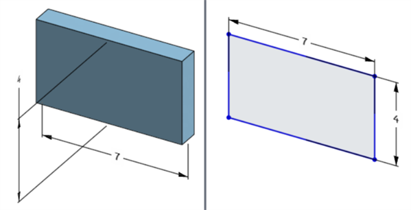
La cota de ancho del modelo se encuentra debajo del modelo (izquierda), pero por encima del boceto (derecha).
-
En el modo Pausar la regeneración, la cota del modelo no se puede editar ni borrar. Sin embargo, se puede seguir editando la operación o activar o desactivar la tolerancia de una cota. Los cambios surten efecto al hacer clic en la marca de verificación Regenerar operaciones y salir del banner Regeneración pausada.
-
Las configuraciones funcionan del modo esperado. Sin embargo, la cota del cuadro de diálogo Contexto de cota no está rodeada por un contorno naranja de guiones para indicar que está configurada. Las cota de boceto configuradas no se pueden editar.
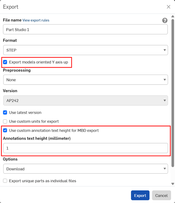
Al exportar piezas, los datos MBD se pueden exportar al formato de archivo STEP. Se recomienda definir la siguiente configuración:
Los datos MBD no se exportan para piezas compuestas cerradas. Esta advertencia aparece durante la exportación en el cuadro de diálogo Exportar si el documento está abierto. Sin embargo, si una pieza se selecciona y se exporta desde una lista de resultados de documentos de búsqueda avanzada, la advertencia no se muestra, pero los datos de MBD aún no se exportan.
-
Active la casilla Exportar modelos orientados con el eje Y hacia arriba.
-
Según el tamaño del modelo, es posible que sea necesario activar la opción Usar altura personalizada de texto de anotación para la exportación de MBD y seleccionar un valor de Altura del texto de anotaciones adecuado para que se corresponda con el tamaño del modelo.
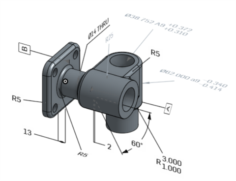
Modelo original en Onshape
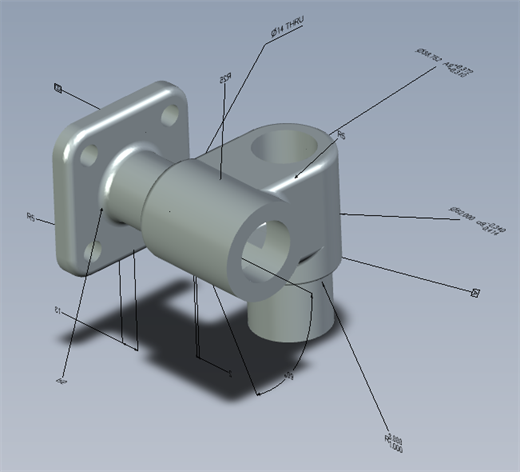
Modelo exportado con la opción "Usar altura personalizada de texto de anotación para la exportación de MBD" desactivada.
Modelo exportado con la opción "Usar altura personalizada de texto de anotación para la exportación de MBD" activada y definida en 10 mm.
Durante la exportación, las tolerancias geométricas con múltiples marcos de tolerancia tienen el Texto superior combinado con el marco superior y el Texto inferior combinado con el marco inferior.
A continuación se proporcionan ejemplos de MBD cuando se trabaja con tolerancias de operación y cota:
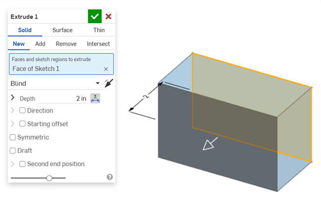
Cota Profundidad:
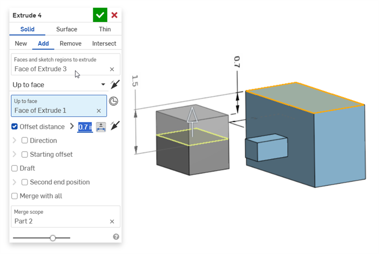
Cota Distancia de equidistancia (con una pieza compuesta):
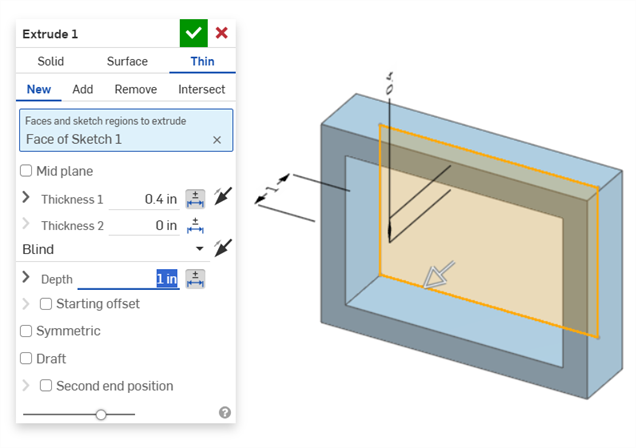
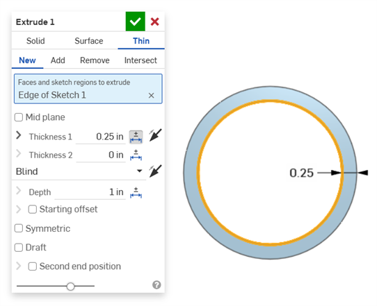
Extrusión fina (cotas Espesor 1 y Profundidad):
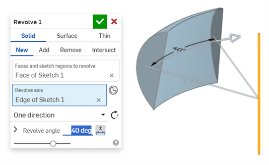
Hacer revolución (cota Ángulo de revolución):
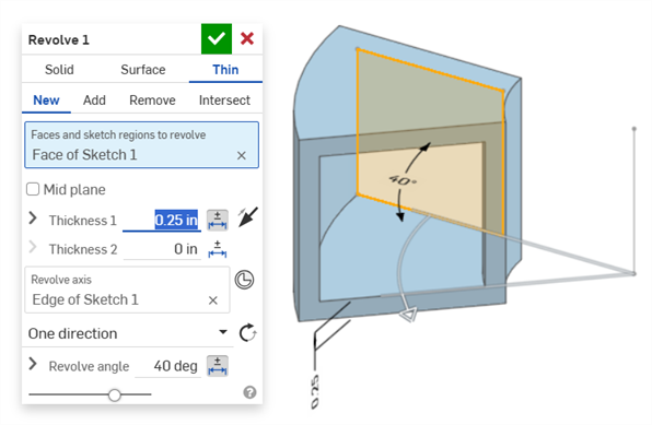
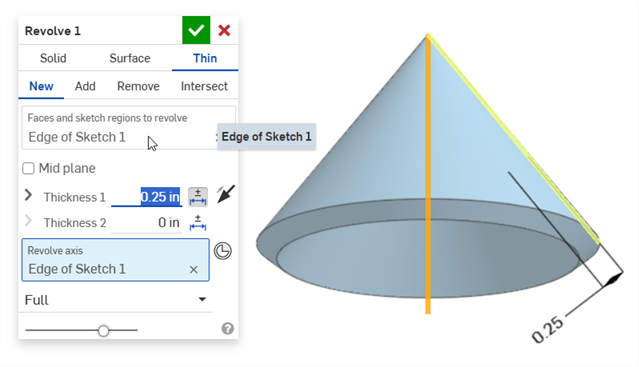
Hacer revolución (cotas Espesor 1 y Ángulo de revolución):
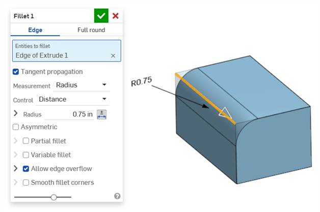
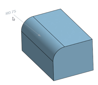
Redondeo (cota Radio):
Creación de una cota de redondeo de conducción mediante la herramienta Cota de redondeo de la tabla inspección en la barra de herramientas de anotación:
En la herramienta Cota del panel de inspección (![]() ) siempre se usan tolerancias predeterminadas lineales o angulares. Al acotar una cara redondeada con ella, se aplica un tipo de tolerancia lineal predeterminada. Por este motivo, se recomienda aplicar las tolerancias de redondeo desde el cuadro de diálogo Operación de redondeo (para una cota de referencia) o utilizar el valor de Cota de redondeo del panel de inspección (para una cota de conducción).
) siempre se usan tolerancias predeterminadas lineales o angulares. Al acotar una cara redondeada con ella, se aplica un tipo de tolerancia lineal predeterminada. Por este motivo, se recomienda aplicar las tolerancias de redondeo desde el cuadro de diálogo Operación de redondeo (para una cota de referencia) o utilizar el valor de Cota de redondeo del panel de inspección (para una cota de conducción).
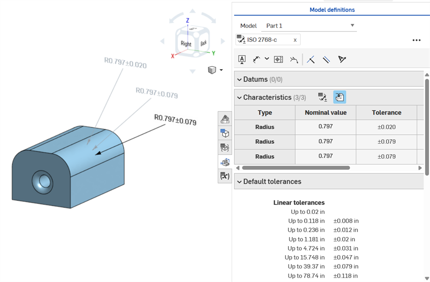
Acotación de una cara de redondeo: anotación en sentido horario. Mediante la herramienta Cota (de conducción; anotada en gris), con la herramienta Cota de redondeo (de referencia; anotada en gris) y hacer que el valor de radio de la operación de redondeo sea tolerante (de referencia; anotada en negro). Las tres cotas se muestran en la tabla de características.
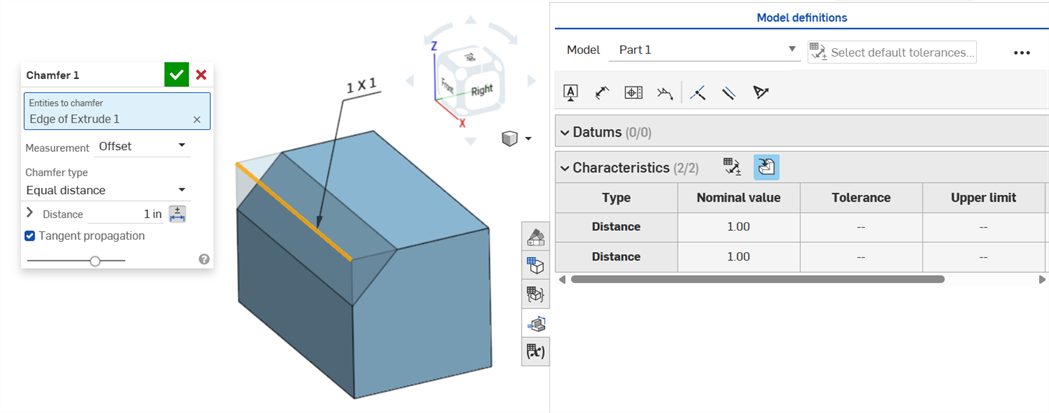
Un chaflán se define como la distancia al ángulo o la distancia a la distancia entre una cara y una arista. Las cotas del ancho del chaflán se especifican como la distancia desde una arista hasta la arista virtual. La visualización de la arista virtual se añade a la arista acotada, incluida una curva de guiones.
-
Las tolerancias no se desactivan cuando se utiliza una medición de tangente, ya que pueden funcionar en determinados casos y, especialmente, cuando se tiene en cuenta la tolerancia especificada.
-
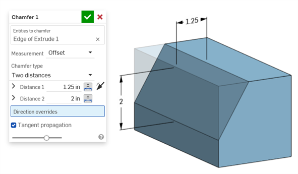
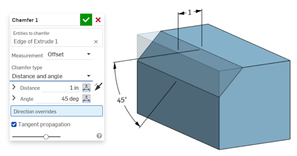
En situaciones en las que se utilizan dos medidas de chaflán (dos distancias o distancia y ángulo), el usuario no tiene que crear tolerancias para ambas. Las tolerancias solo se pueden añadir a un parámetro, si es necesario.
El tipo de chaflán de distancia igual muestra dos valores de tolerancia de distancia, que se reflejan en la tabla, aunque solo hay una opción de tolerancia de distancia en el cuadro de diálogo:
Ejemplo de dos distancias:
Ejemplo de distancia y ángulo:
En los casos en los que el chaflán dé como resultado una distancia variable (por ejemplo, si el chaflán se aplica a la cara de un cilindro que está conectado perpendicularmente a otro cilindro), intente seleccionar la tangente para la medición para que la distancia sea uniforme a lo largo de la arista:
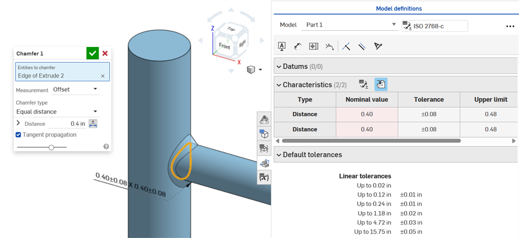
Chaflán no uniforme que utiliza una medición de equidistancia que muestra un error de valor nominal.
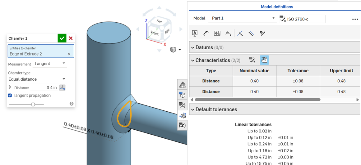
El chaflán uniforme que utiliza una medición de tangente da como resultado un valor nominal sin errores.
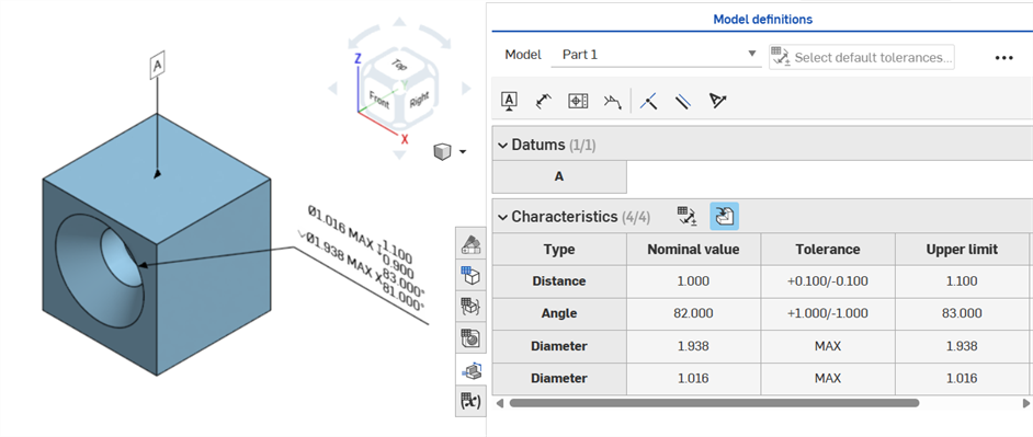
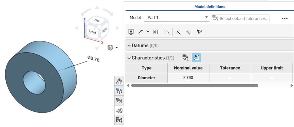
Si se coloca una tolerancia en una operación de taladro, se puede mostrar en la tabla de inspección.
Aspectos a tener en cuenta:
-
Las cotas de taladro solo están visibles como filas en la tabla de inspección. No hay cotas colocadas en el área gráfica. Esto se hace para no saturar el área gráfica con notas.
-
Antes de que las cotas de taladro estén visibles en la tabla de inspección, se debe colocar otra nota (una referencia, por ejemplo) en la pieza.
-
Solo se muestra un conjunto de cotas (diámetro, distancia o ángulo) por operación de taladro. Los taladros con patrón o adicionales de la misma operación no se acotan por separado.
-
La cota personalizada del ángulo de punta no se admite actualmente y no crea una fila en la tabla de inspección.
-
El resaltado cruzado funciona de la siguiente manera:
-
La distancia (profundidad) no está resaltada de manera cruzada porque no hay caras en ninguno de los extremos del taladro y, actualmente, el MBD no admite aristas.
-
El diámetro, la distancia (profundidad de escariado) y el ángulo (ángulo de avellanado) resaltan en forma cruzada una sola cara.
-
Las cotas de taladro están visibles en la tabla de inspección después de añadir una referencia a una de las caras de la pieza.
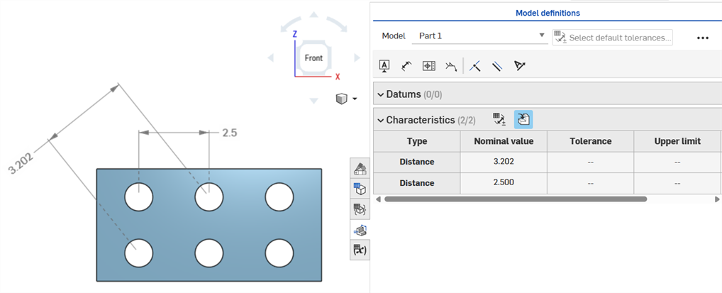
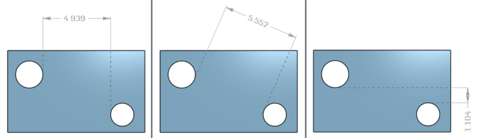
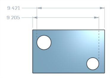
Cotas de distancia de ejes entre círculos centrales mediante la herramienta Cota (![]() ):
):
Cotas horizontales, diagonales y verticales mínimas entre dos caras cilíndricas mediante la herramienta Cota mínima (![]() ):
):
Cotas mínimas entre cilindros y aristas:
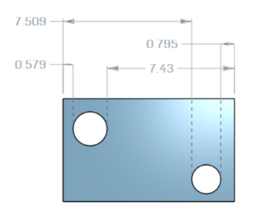
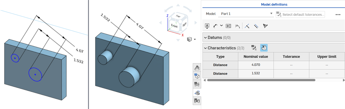
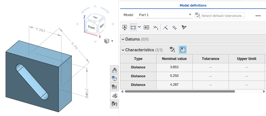
Una vez creada la pieza (derecha), se muestra una cota diagonal mínima añadida en un boceto (izquierda) en la tabla de características:
Las cotas mínimas horizontales y verticales no se pueden crear actualmente en un boceto.
Cotas horizontales, diagonales y verticales mínimas entre dos caras cilíndricas mediante la herramienta Cota máxima (![]() ):
):
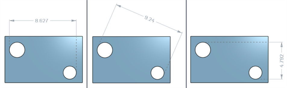
Cotas máximas entre cilindros y aristas:
Cotas horizontales, diagonales y verticales máximas entre las caras del arco de una ranura:
Una cota diagonal máxima añadida en un boceto (izquierda) se muestra en la tabla de características una vez creada la pieza (derecha):
Las cotas máximas horizontales y verticales no se pueden crear actualmente en un boceto.
El espesor se muestra en la tabla de inspección como una fila Distancia.
Extrusión delgada (cota Espesor 1):
Revolución delgada (cota Espesor 1):
Una cota de eje del boceto con la tolerancia activada:
Si la línea central se utiliza como eje sobre el que girar la geometría del boceto, se muestra como una cota de diámetro cuando se abre la tabla de inspección:
A medida que se agregan anotaciones, se realizan cambios en el modelo y se aplican actualizaciones de operación, Onshape intenta validar automáticamente los datos de MBD asociados.
Las validaciones se realizan por pieza. Por lo tanto, las anotaciones deben hacer referencia a la geometría de la misma pieza o pieza compuesta.
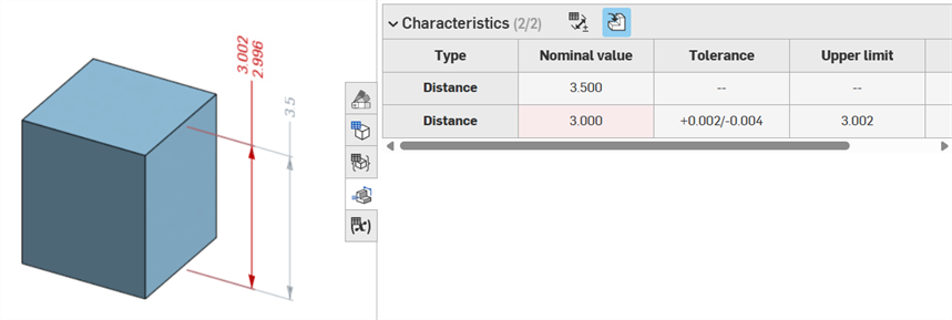
Cuando se invalida una característica, tanto la anotación como la característica correspondiente de la tabla de inspección aparecen en rojo.
Las características no válidas se dividen en dos categorías: referencias perdidas y discrepancias de valores.
Una referencia perdida se produce cuando la geometría que se utiliza para definir una característica ya no existe o ha cambiado de manera que rompe la asociación. Esto puede deberse a la eliminación de una operación, a la sustitución de una cara o a otro cambio topológico.
Se produce una discrepancia de valores cuando el valor de la geometría de referencia ya no coincide con la tolerancia definida. Esto puede ocurrir, por ejemplo, cuando el diámetro de un taladro se incrementa más allá de los límites especificados.
Las características no válidas se resuelven mediante la evaluación de las causas posibles.
Al utilizar la opción Comparar, seleccione caras para ver sus anotaciones, tolerancias y características asociadas.
Para validar y resolver los errores, modifique la lista de operaciones y las anotaciones de MBD.
Los errores de MBD no crean anotaciones ni entradas de fila en la tabla de inspección, a menos que se realice un ajuste en el modelo que invalide una entrada de fila de anotación existente.
Los errores se muestran en rojo, de forma similar a otros errores de Onshape:
Error que se genera al extruir desde o hacia un sólido. La anotación no genera una entrada de fila en la tabla de inspección.
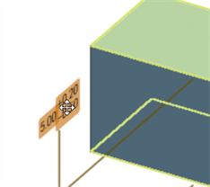
Si la geometría se modifica para invalidar una anotación especificada, su anotación correspondiente aparece en rojo en el área gráfica y se resalta en rojo en la tabla de inspección, lo que indica un error. Por ejemplo, la cara superior del cuadro se movió 0,5 pulgadas, por lo que el valor medido (3,5 pulgadas) difiere del valor especificado (3,0 pulgadas):
Ejemplos de errores
-
Falta una referencia para esta anotación: se produce cuando falta una referencia. Por ejemplo, la pieza A se extruye hasta la cara de la pieza B y se añade una tolerancia a la distancia de equidistancia de la extrusión de la pieza A.
-
Ambas caras deben proceder de la misma pieza: las definiciones de modelo solo son válidas por pieza. Por ejemplo, no se puede acotar la distancia entre una cara de la pieza A y una cara de la pieza B.
-
Las anotaciones de MBD siempre deben estar asociadas a las caras. Actualmente, no se puede hacer referencia a aristas ni vértices.
-
Las definiciones de modelo solo son válidas por pieza. Las piezas compuestas también son válidas. Por ejemplo, se puede acotar la distancia entre 2 caras de la pieza A o 2 caras de la pieza B, pero no entre una cara de la pieza A y una cara de la pieza B. Para ello, cree primero una pieza C compuesta a partir de la pieza A y la pieza B. A continuación, puede acotar la distancia entre estas dos caras.
-
Al pasar el puntero del mouse por encima de la fila Tipo de la tabla de inspección, se resalta de forma cruzada la cota en el área gráfica.
-
Al modificar la geometría de una pieza, todas las definiciones de modelo asociadas se resaltan en naranja:
-
Si una pieza o un elemento Part Studio se deriva mediante la operación Derivada, todas las definiciones del modelo son de solo lectura y no se pueden editar. Se puede seguir moviendo las anotaciones y las cotas de conducción se siguen actualizando si se modifica la geometría derivada. Sin embargo, las definiciones del modelo subyacente solo pueden ajustarse en el elemento Part Studio de origen y, a continuación, actualizarse en la operación Derivada. Consulte Derivado para obtener más información.
-
Se pueden agregar comentarios y etiquetar las cotas de boceto tolerantes, las cotas de las operaciones, las anotaciones de taladro y las anotaciones de la tabla de inspección (cotas, datos de referencia, tolerancias geométricas) en el área gráfica. Para obtener más información, consulte Agregar comentarios a las anotaciones de MBD.