Modellbasierte Definition (MBD)
![]()
![]()
![]()
Verfügbar in: Part Studios
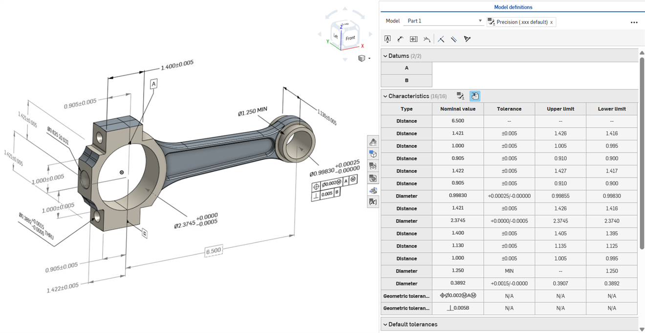
Der Begriff „Modellbasierte Definition (MBD)“ bezieht sich auf den Prozess der Bemaßung und Beschriftung des Modells im Part Studio, damit das Modell alle nötigen Daten für die Produktdefinition enthält. Durch die MBD wird das Modell zur maßgeblichen Quelle für alle nachfolgenden Entwicklungs- und Konstruktionsarbeiten. Dieses Modell kann von Lieferanten sowie unternehmensintern verwendet werden.
MBD-Daten funktionieren in Verbindung mit Toleranzoptionen, bei denen Skizzen- und Feature-Bemaßungen tolerant gemacht werden, sowie zusammen mit der Prüftabelle, in der MBD-Daten für jedes Bauteil in einem Part Studio angezeigt, hinzugefügt und exportiert werden können.
Die MBD soll keine Zeichnungen ersetzen. Sie dient dazu, Informationen zur Produktfertigung (PMI) und modellbasierte Informationen des Enterprise (MBE) für zusätzliche oder alternative nachgelagerte Zwecke zu erfassen und zu erweitern.
Die MDB bietet z. B. Vorteile wie:
-
im Part-Studio-Modell eingebettete Bemaßungs- und Beschriftungs-Metadaten
-
bessere Echtzeit-Zusammenarbeit am Modell im Part Studio
-
eine einzige, zentrale Informationsquelle für Konstrukteure im gesamten Unternehmen
-
Link zu nachgelagerten Prozessen wie der Prüfung von Koordinatenmessgeräten (KMG)
Steuernde MBD-Skizzen- und Feature-Bemaßungen können direkt im Grafikbereich bearbeitet werden.
Informationen zur Fertigung des Produkts können bei im Grafikbereich bearbeitet werden, wenn die Prüftabelle geöffnet ist, oder innerhalb der Skizzen und Features, in denen sie ursprünglich definiert wurden.
Bearbeiten Sie die Toleranzen, indem Sie im Grafikbereich auf die Bemaßung doppelklicken. Wenn die Bemaßung auf die Feature-Liste referenziert, öffnet Onshape die Skizze oder das Feature zur Bearbeitung. Wurde die Bemaßung mit der Symbolleiste „Beschriftung“ erstellt, bearbeiten Sie sie im Grafikbereich. Wenn sich das Modell und die Toleranzen ändern, wird die Prüftabelle in Echtzeit aktualisiert.
Mit zwei Schaltflächen zum Umschalten filtern Sie in der Eigenschaftentabelle die Zeilen. Zuerst werden Beschriftungen mit angewendeten Standardtoleranzen angezeigt und Beschriftungen aus abgeleiteter Geometrie werden ausgeblendet. Abgeleitete Beschriftungen können nur aktualisiert werden, indem die Quelle geändert wird.
Verwenden Sie Quermarkierungen, um die zugehörigen Modellreferenzen schnell zu identifizieren und zu finden. Zeigen Sie mit der Maus auf die Zellen in der Prüftabelle, um das referenzierte Bauteil, die Flächen, die Features und die zugehörigen Beschriftungen im Grafikbereich mit einer Quermarkierung zu versehen. Wählen Sie eine Beschriftung im Grafikbereich aus oder klicken Sie auf eine Bezugspunkt- oder Typzelle, um die Markierung sichtbar zu lassen.
Entfernen Sie eine Beschriftung, indem Sie sie im Grafikbereich auswählen und auf „Löschen“ klicken. Das Löschen einer Beschriftung, die auf die Feature-Liste referenziert, entfernt die Toleranzoptionen aus der Skizzenbemaßung oder dem Feature-Wert sowie die Zeile aus der Eigenschaftentabelle. Wenn Sie eine Beschriftung löschen, die mit der Beschriftungs-Symbolleiste platziert wurde, wird sie aus der Tabelle entfernt. Abgeleitete Beschriftungen können nicht gelöscht werden.
-
Öffnen Sie die Prüfpalette (
 ), um die MBD-Bemaßungen in den Grafikbereichen anzuzeigen (linkes Bild unten).
 -
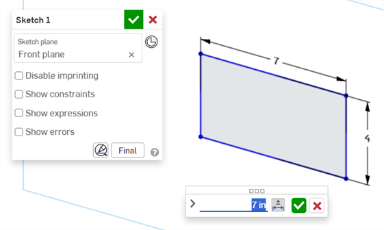
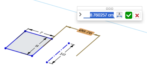
Doppelklicken Sie auf die steuernde Bemaßung, die mit einer Skizze verknüpft ist (rechtes Bild unten):
Das Bemaßungskontext-Dialogfenster wird geöffnet, wobei der Kontext für den Bemaßungswert platziert wird. Gleichzeitig wird das Dialogfenster „Skizze“ geöffnet:
-
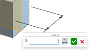
Geben Sie mit der Tastatur einen numerischen Wert ein oder verwenden Sie die Auf-/Abwärtspfeile, um den Wert im Bemaßungskontext-Dialogfenster zu erhöhen. Wenn dieser Wert angepasst wird, wird die Skizze dynamisch aktualisiert.
Wenn Sie einen numerischen Wert eingeben, drücken Sie die Tabulatortaste, um zu sehen, wie der Skizzenwert aktualisiert wird.
-
Drücken Sie die Eingabetaste auf der Tastatur oder klicken Sie im Bemaßungskontext-Dialogfenster auf das Häkchen (
 ), um dieses Dialogfenster zu schließen:
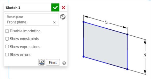
-
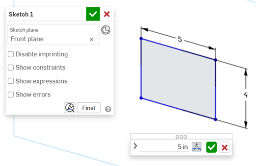
Klicken Sie im Dialogfenster „Skizze“ auf das Häkchen (
), um den neuen Skizzenwert zu akzeptieren.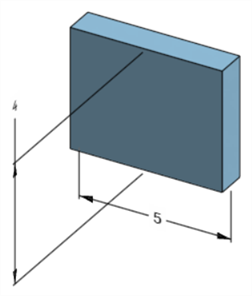
Die bearbeitete Skizzenbemaßung, die die Bemaßung des Modells anpasst
-
Öffnen Sie die Prüfpalette (
), um die MBD-Bemaßungen in den Grafikbereichen anzuzeigen (linkes Bild unten). -
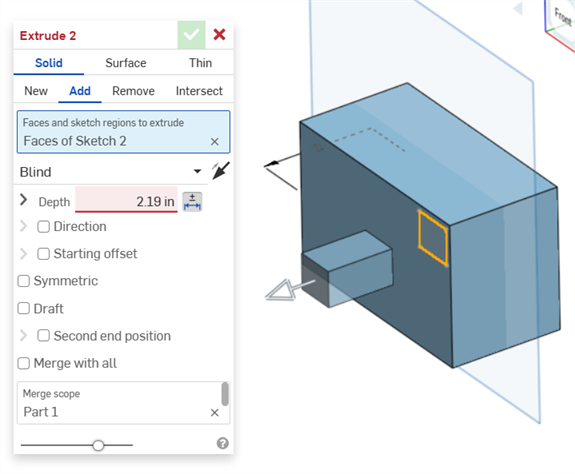
Doppelklicken Sie auf die steuernde Bemaßung, die mit einem Feature verbunden ist (rechtes Bild unten):
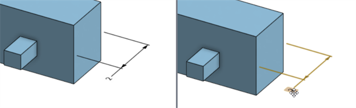
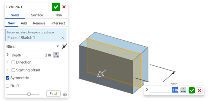
Das Bemaßungskontext-Dialogfenster wird geöffnet, wobei der Kontext für den Bemaßungswert platziert wird. Gleichzeitig öffnet sich das zugehörige Feature-Dialogfenster (in diesem Beispiel Linear austragen):
-
Geben Sie mit der Tastatur einen numerischen Wert ein oder verwenden Sie die Auf-/Abwärtspfeile, um den Wert im Bemaßungskontext-Dialogfenster zu erhöhen. Wenn dieser Wert angepasst wird, werden sowohl das Modell als auch der Wert im Feature-Dialogfenster dynamisch aktualisiert.
Wenn Sie einen Wert numerisch eingeben, drücken Sie die Tabulatortaste, um zu sehen, wie der Wert im Feature-Dialogfenster aktualisiert wird.
-
Drücken Sie die Eingabetaste auf der Tastatur oder klicken Sie im Bemaßungskontext-Dialogfenster auf das Häkchen (
), um dieses Dialogfenster zu schließen: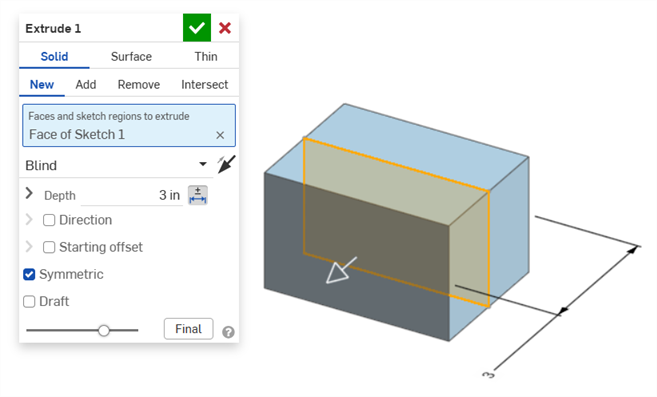
-
Drücken Sie erneut die Eingabetaste auf der Tastatur oder klicken Sie auf das Häkchen im Feature-Dialogfenster (
), um dieses Dialogfenster zu schließen: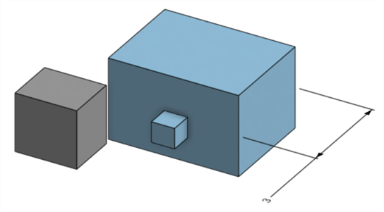
Die bearbeitete Feature-Bemaßung, die die Bemaßung des Modells anpasst
So löschen Sie eine Beschriftung:
-
Wählen Sie im Grafikbereich die Beschriftung aus:
-
Drücken Sie die Entfernen-Taste.
-
Die Beschriftung wird aus dem Grafikbereich und der Prüftabelle gelöscht.
Wenn es sich bei der Beschriftung um eine Skizze oder eine Feature-Bemaßung handelt:
-
Die Werte der Toleranzoptionen der Bemaßung werden gelöscht.
-
Das Symbol Toleranzoptionen (
 ) ist abgewählt.
 -
Der Bemaßungswert im Skizzen- oder Feature-Dialogfenster wird nicht gelöscht.
-
Beschriftungen können in folgenden Fällen nicht gelöscht werden:
-
Die Beschriftung ist abgeleitet.
-
Die Beschriftung wird in einem benutzerdefinierten Feature erstellt, bei der der Parameter tolerant gemacht wird, die Umschaltfunktion für die Toleranz sich jedoch nicht vom Benutzer verwenden lässt.
In beiden Fällen wird die folgende Meldung angezeigt:

-
Gesteuerte Bemaßungen können nicht bearbeitet werden. Ein Doppelklick auf eine gesteuerte Bemaßung öffnet den das Bemaßungskontext-Dialogfenster, aber die Werte in dem Dialogfenster können nicht bearbeitet werden.
-
Abgeleitete Bemaßungen können nicht bearbeitet werden. Wenn Sie von einem abgeleiteten Bauteil aus auf eine steuernde oder gesteuerte Bemaßung doppelklicken, wird das Bemaßungskontext-Dialogfenster nicht geöffnet.
-
Um die Eingabe im Bemaßungskontext-Dialogfenster abzubrechen, drücken Sie die Esc-Taste. Wenn Sie eine Feature-Bemaßung bearbeiten, werden das Bemaßungskontext-Dialogfenster und das Feature-Dialogfenster gleichzeitig geschlossen. Wenn Sie eine Skizzenbemaßung bearbeiten, wird nur das Bemaßungskontext-Dialogfenster geschlossen. Das Skizzen-Dialogfenster muss manuell geschlossen werden (durch Klicken auf das X-Symbol).
-
Alternativ kann bei gleichzeitig geöffnetem Feature- und Bemaßungskontext-Dialogfenster der Wert im Feature-Dialogfenster ausgewählt und bearbeitet werden, wodurch sowohl das Bemaßungskontext-Dialogfenster als auch das Modell dynamisch aktualisiert werden. Sobald die Bearbeitung hier abgeschlossen ist, werden durch Drücken der Eingabetaste sowohl das Feature- und Bemaßungskontext-Dialogfenster gleichzeitig geschlossen.
-
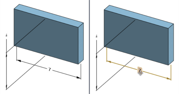
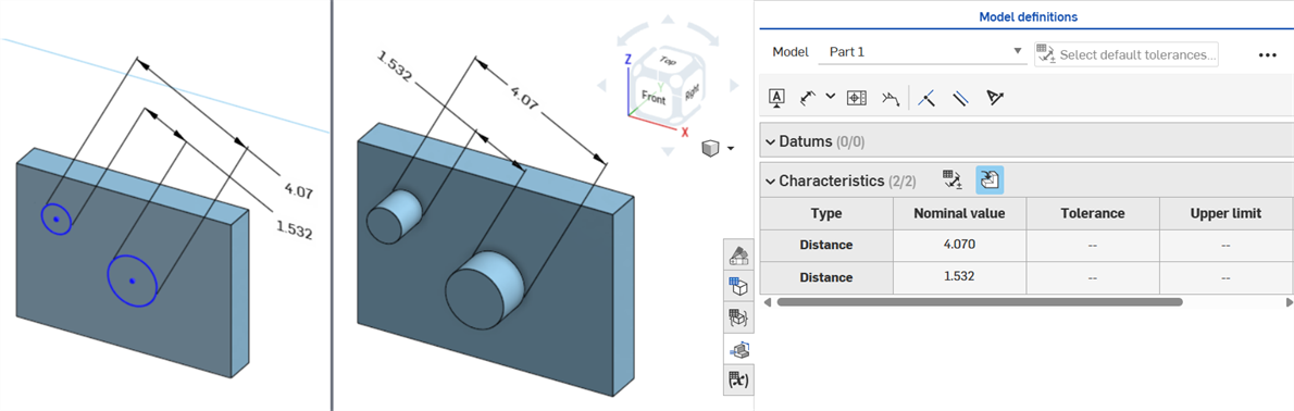
Die Position der Modellbemaßung und die Position der entsprechenden Skizzenbemaßung sind nicht fest miteinander verbunden, sondern unabhängig voneinander:
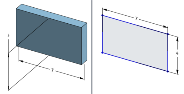
Die Breitenabmessung des Modells befindet sich unter dem Modell (links), aber über der Skizze (rechts).
-
Im Modus Neuaufbau unterbrechen kann die Bemaßung des Modells nicht bearbeitet oder gelöscht werden. Sie können das Feature jedoch weiterhin bearbeiten oder die Toleranz einer Bemaßung mit der Umschaltfunktion aktivieren oder deaktivieren. Die Änderungen werden wirksam, nachdem Sie im Banner „Neuaufbau unterbrochen“ auf das Häkchen Features neu aufbauen und beenden geklickt haben.
-
Die Konfigurationen funktionieren wie erwartet. Allerdings ist Bemaßung im Bemaßungskontext-Dialogfenster von keiner gestrichelten orangefarbenen Umrandung umgeben, die anzeigen würde, dass sie konfiguriert ist. Konfigurierte Skizzenbemaßungen können nicht bearbeitet werden.
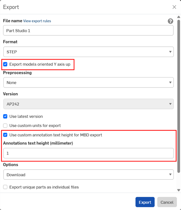
MBD-Daten können beim Export von Bauteile im STEP-Dateiformat exportiert werden. Die folgenden Einstellungen werden empfohlen:
MBD-Daten werden nicht für geschlossene zusammengesetzte Bauteile exportiert. Diese Warnung wird während des Exports im Export-Dialogfenster angezeigt, wenn das Dokument geöffnet ist. Wird jedoch ein Bauteil aus einer Dokumenten-Ergebnisliste für die erweiterte Suche ausgewählt und exportiert, wird zwar die Warnung nicht angezeigt, aber die MBD-Daten werden trotzdem nicht exportiert.
-
Aktivieren Sie das Kontrollkästchen Modelle mit der Y-Achse nach oben exportieren.
-
Abhängig von der Größe Ihres Modells müssen Sie möglicherweise die Option Benutzerdefinierte Beschriftungstexthöhe für MBD-Export verwenden aktivieren und eine geeignete Beschriftungstexthöhe auswählen, die Ihrer Modellgröße entspricht.
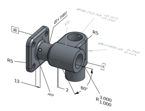
Originalmodell in Onshape
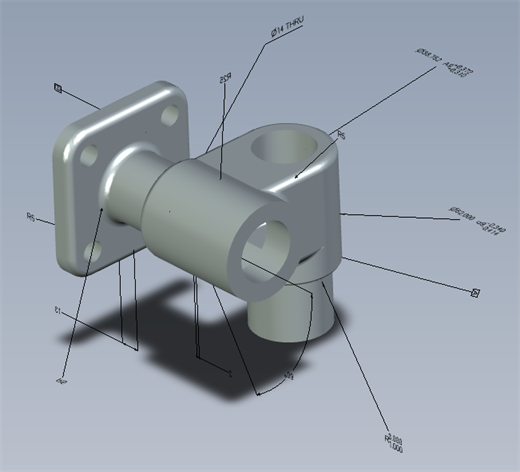
Exportiertes Modell mit deaktivierter Option „Benutzerdefinierte Beschriftungstexthöhe für MBD-Export verwenden“
Exportiertes Modell mit aktivierter Option „Benutzerdefinierte Beschriftungstexthöhe für MBD-Export verwenden“, bei dem die Beschriftungstexthöhe auf 10 mm festgelegt ist.
Beim Export wird bei Form- und Lagetoleranzen mit mehreren Toleranzrahmen der obere Text mit dem oberen Rahmen und der untere Text mit dem unteren Rahmen kombiniert.
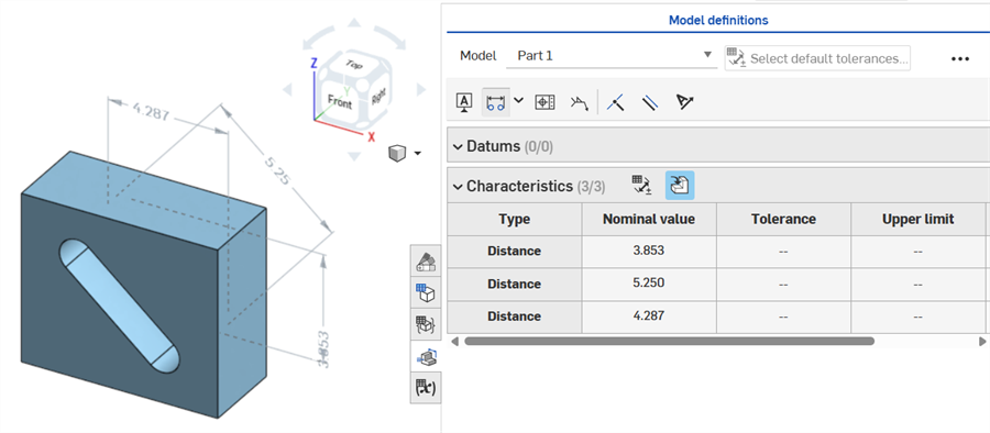
Im Folgenden finden Sie MBD-Beispiele für die Arbeit mit Feature- und Bemaßungstoleranzen:
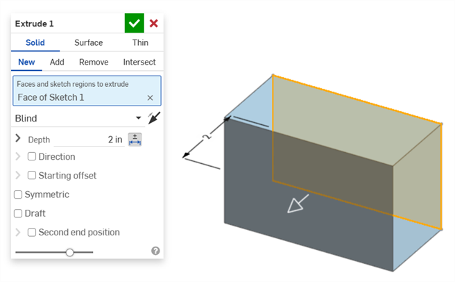
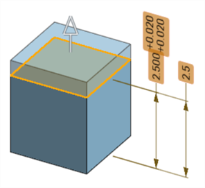
Tiefenbemaßung:
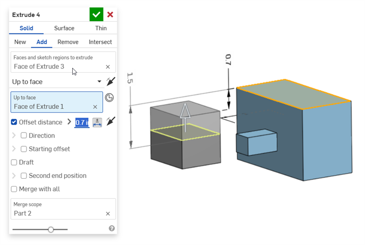
Versatz-Abstandsbemaßung (mit einem zusammengesetzten Bauteil):
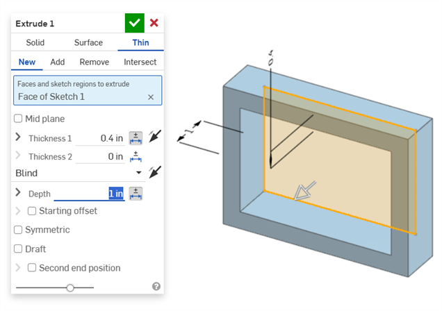
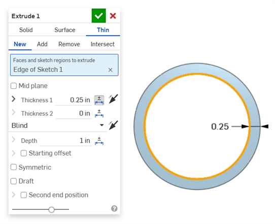
Dünnes Extrudieren (Dicke 1 und Tiefenbemaßungen):
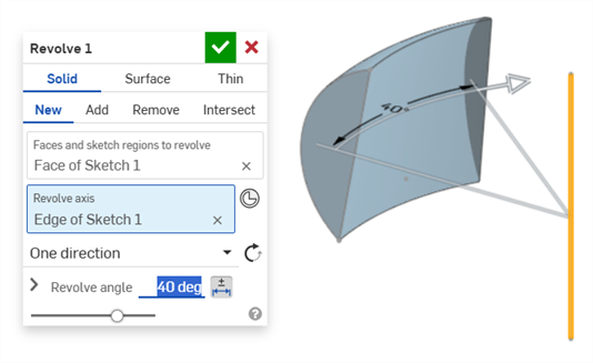
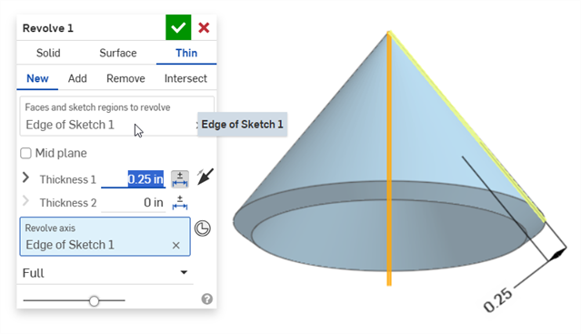
Rotation (Rotationswinkelbemaßung):
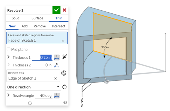
Rotation (Dicke 1 und Rotationswinkelbemaßungen):
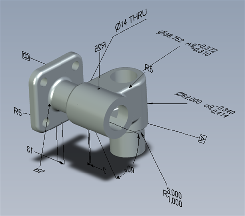
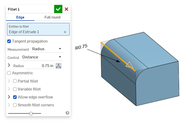
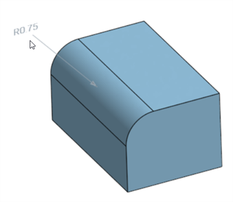
Verrundung (Radiusbemaßung):
Erstellen einer gesteuerten Verrundungsbemaßung mit dem Tool Verrundungsbemaßung aus der Symbolleiste „Beschriftung“:
Das Bemaßungstool (![]() ) der Prüfpalette verwendet immer lineare oder Winkel-Standardtoleranzen. Wenn Sie eine abgerundete Fläche damit bemaßen, wird ein linearer Standardtoleranztyp angewendet. Deshalb wird empfohlen, entweder die Verrundungstoleranzen im Dialogfenster des Verrundungs-Features (für eine steuernde Bemaßung) oder die Verrundungsbemaßung aus der Prüfpalette (für eine gesteuerte Bemaßung) zu verwenden.
) der Prüfpalette verwendet immer lineare oder Winkel-Standardtoleranzen. Wenn Sie eine abgerundete Fläche damit bemaßen, wird ein linearer Standardtoleranztyp angewendet. Deshalb wird empfohlen, entweder die Verrundungstoleranzen im Dialogfenster des Verrundungs-Features (für eine steuernde Bemaßung) oder die Verrundungsbemaßung aus der Prüfpalette (für eine gesteuerte Bemaßung) zu verwenden.
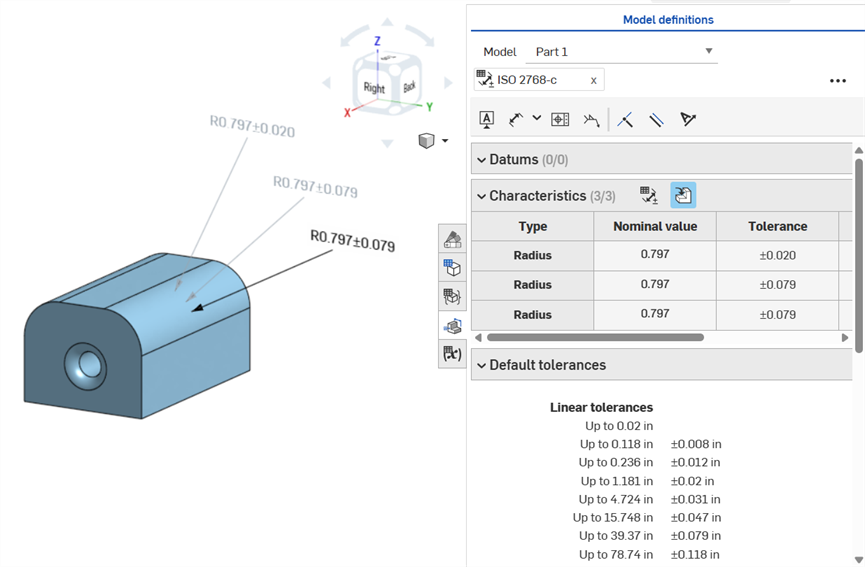
Bemaßen einer Verrundungsfläche (im Uhrzeigersinn beschriftet): mit dem Bemaßungstool (gesteuert, grau beschriftet), mit dem Verrundungs-Bemaßungstool (gesteuert, grau beschriftet) und Radiuswert des Verrundungs-Features als tolerant anlegen (steuernd, schwarz beschriftet). Alle drei Bemaßungen sind in der Eigenschaften-Tabelle aufgeführt.
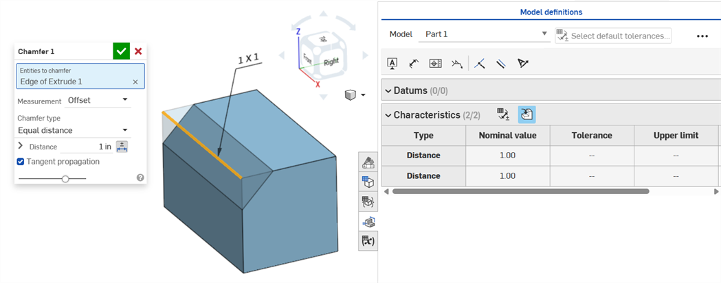
Eine Fase wird als Abstand zum Winkel oder Abstand zwischen einer Fläche und einer Kante definiert. Die Bemaßungen der Fasenbreite werden als Abstand zum Abstand zwischen einer Kante zu einem virtuellen Eckpunkt angegeben. Die Anzeige von virtuellen Eckpunkten wird zur bemaßten Kante hinzugefügt, einschließlich einer gestrichelten Kurve.
-
Toleranzen sind nicht deaktiviert, wenn eine Tangentenmessung verwendet wird (was in bestimmten Fällen funktionieren kann, insbesondere wenn die angegebene Toleranz berücksichtigt wird).
-
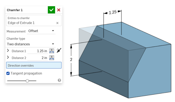
In Situationen, in denen zwei Fasenmessungen verwendet werden (zwei Abstände oder Abstand und Winkel), müssen Sie keine Toleranzen für beide erstellen. Toleranzen können nur zu einem Parameter hinzugefügt werden, falls dies erforderlich ist.
Fasentyp mit gleichem Abstand zeigt zwei Abstandstoleranzwerte an, die in der Tabelle angezeigt werden, obwohl es im Dialogfenster nur eine Option für die Abstandstoleranz gibt:
Beispiel für zwei Abstände:
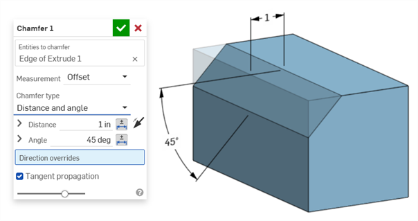
Beispiel für Abstand und Winkel:
In Fällen, in denen die Fase zu einem variablen Abstand führt (z. B. wenn die Fase auf eine Zylinderfläche angewendet wird, die senkrecht mit einem anderen Zylinder verbunden ist), versuchen Sie, eine Tangente für die Messung auszuwählen, um entlang der Kante den gleichen Abstand zu erhalten:
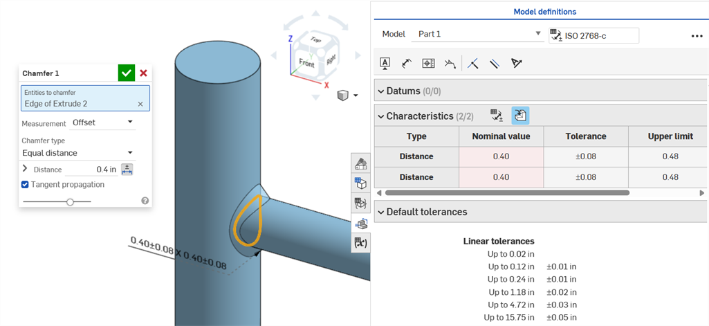
Eine nicht gleichförmige Fase mit einer Versatzmessung, die einen Nominalwertfehler anzeigt.
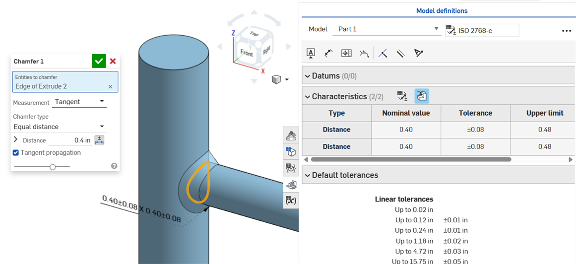
Eine gleichförmige Fase mit einer Tangentenmessung ergibt einen Nominalwert ohne Fehler.
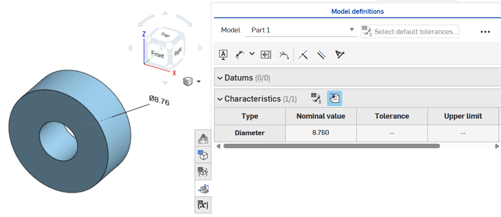
Wenn einem Bohrungs-Feature eine Toleranz zugewiesen wird, kann diese in der Prüftabelle angezeigt werden.
Beachten Sie dabei Folgendes:
-
Bohrungsbemaßungen sind in der Prüftabelle nur als Zeilen sichtbar. Im Grafikbereich sind keine Bemaßungen platziert. Dies geschieht, um den Grafikbereich nicht mit Textboxen zu überladen.
-
Damit die Bohrungsbemaßungen in der Prüftabelle angezeigt werden, muss eine weitere Textbox (z. B. ein Bezugspunkt) auf dem Bauteil platziert werden.
-
Pro Bohrungs-Feature wird nur ein Bemaßungssatz (Durchmesser, Abstand und/oder Winkel) angezeigt. Gemusterte Bohrungen oder zusätzliche Bohrungen im selben Feature werden nicht separat bemaßt.
-
Die benutzerdefinierte Bemaßung des Spitzenwinkels wird derzeit nicht unterstützt und führt zu keiner Zeile in der Prüftabelle.
-
Quermarkierungen funktionieren wie folgt:
-
Abstand (Tiefe) ist nicht markiert, weil sich an beiden Enden der Bohrung keine Flächen befinden und Kanten derzeit nicht für MBD unterstützt werden.
-
Durchmesser, Abstand (Stirnsenkungstiefe) und Winkel (Formsenkungswinkel) heben eine einzelne Fläche mit Quermarkierungen hervor.
-
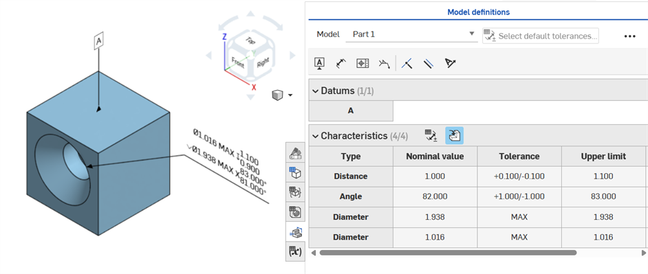
Bohrungsbemaßungen werden erst in der Prüftabelle angezeigt, nachdem ein Bezugspunkt zu einer der Flächen des Bauteils hinzugefügt wurde.
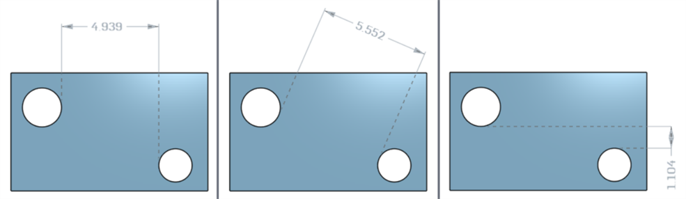
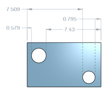
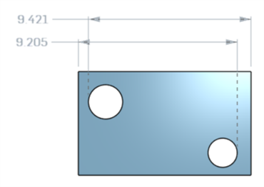
Bemaßungen des Achsenabstands zwischen Mittelkreisen mit dem Bemaßungstool (![]() ):
):
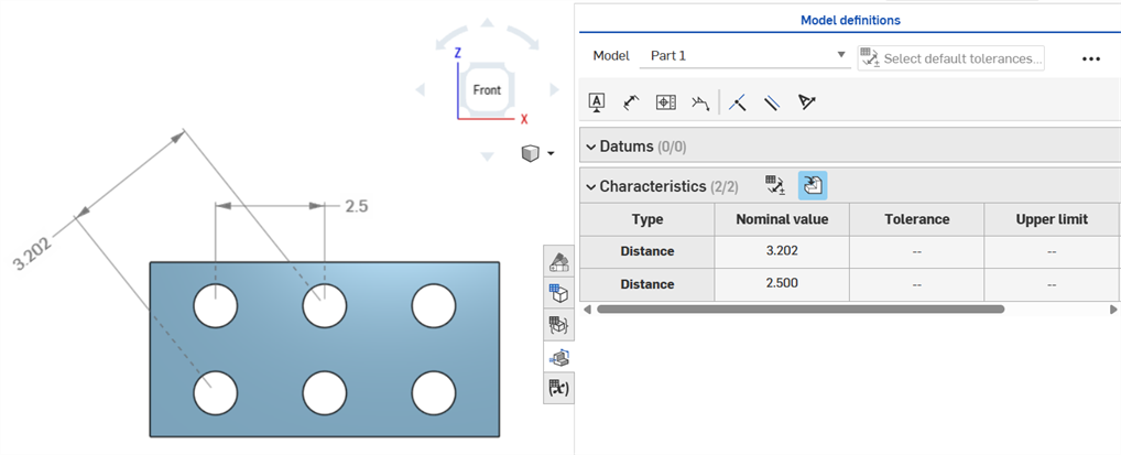
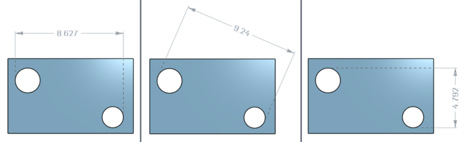
Minimale horizontale, diagonale und vertikale Bemaßungen zwischen zwei zylindrischen Flächen mit dem Tool Minimale Bemaßung (![]() ):
):
Minimale Bemaßungen zwischen Zylindern und Kanten:
Die zu einer Skizze hinzugefügte minimale Diagonalbemaßung (links) wird erst dann in der Eigenschaftentabelle angezeigt, wenn das Bauteil erstellt wurde (rechts):
Horizontale und vertikale minimale Bemaßungen können derzeit nicht in einer Skizze erstellt werden.
Minimale horizontale, diagonale und vertikale Bemaßungen zwischen zwei zylindrischen Flächen unter Verwendung des Tools Maximale Bemaßung (![]() ):
):
Maximale Bemaßungen zwischen Zylindern und Kanten:
Maximale horizontale, diagonale und vertikale Bemaßungen zwischen Bogenflächen in einem Langloch:
Die zu einer Skizze hinzugefügte maximale Diagonalbemaßung (links) wird erst dann in der Eigenschaftentabelle angezeigt, wenn das Bauteil erstellt wurde (rechts):
Horizontale und vertikale maximale Bemaßungen können derzeit nicht in einer Skizze erstellt werden.
Die Dicke wird in der Prüftabelle als Abstandszeile angezeigt.
Dünnes Extrudieren (Bemaßung von Dicke 1):
Dünne Rotation (Bemaßung von Dicke 1):
Skizzenmittellinienbemaßung mit aktivierter Toleranz:
Wenn die Mittellinie für die Skizzengeometrie als Rotationsachse dient und die Prüftabelle gleichzeitig geöffnet ist, wird die Mittellinie als Durchmesserbemaßung angezeigt:
Wenn Anmerkungen hinzugefügt, Modelländerungen vorgenommen und Feature-Updates angewendet werden, versucht Onshape automatisch, die zugehörigen MBD-Daten zu validieren.
Validierungen erfolgen pro Bauteil. Daher müssen Beschriftungen auf die Geometrie desselben Bauteils oder zusammengesetzten Bauteils referenzieren.
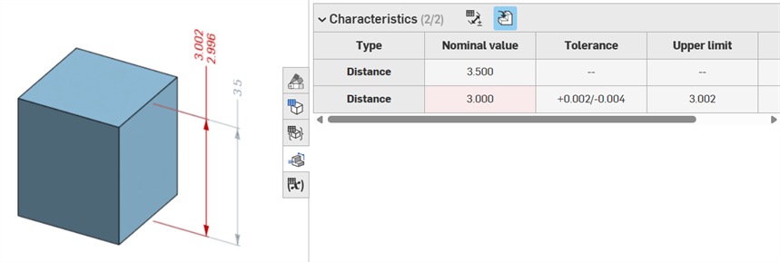
Wenn eine Eigenschaft für ungültig erklärt wird, werden die Beschriftung und die zugehörige Eigenschaft in der Prüftabelle rot dargestellt.
Ungültige Eigenschaften lassen sich in zwei Kategorien einteilen: fehlende Referenzen und nicht übereinstimmende Werte.
Eine fehlende Referenz liegt vor, wenn die Geometrie, die zur Definition einer Eigenschaft verwendet wurde, nicht mehr existiert oder sich so verändert hat, dass die Verbindung unterbrochen wird. Dies kann auf ein gelöschtes Feature, einen Flächenersatz oder eine andere topologische Änderung zurückzuführen sein.
Ein Wertekonflikt tritt auf, wenn der Wert der referenzierten Geometrie nicht mehr der definierten Toleranz entspricht. Das kann zum Beispiel passieren, wenn der Durchmesser einer Bohrung über die angegebenen Grenzwerte hinaus vergrößert wird.
Beheben Sie ungültige Eigenschaften, indem Sie mögliche Ursachen untersuchen.
Wenn Sie „Vergleichen“ verwenden, wählen Sie „Flächen“ aus, um die zugehörigen Anmerkungen, Toleranzen und Eigenschaften anzuzeigen.
Bestätigen und beheben Sie Fehler, indem Sie die Feature-Liste und die MBD-Beschriftungen ändern.
MBD-Fehler führen nicht zu Beschriftungen oder Zeileneinträgen in der Prüftabelle, es sei denn, es wird eine Modellanpassung vorgenommen, durch die ein vorhandener Eintrag in der Beschriftungszeile ungültig wird.
Fehler werden rot angezeigt, ähnlich wie bei anderen Onshape-Fehlern:
Beim linearen Austragen aus oder in einen Volumenkörper ist ein Fehler aufgetreten. Die Beschriftung generiert keinen Zeileneintrag in der Prüftabelle.
Wenn die Geometrie geändert wird, um eine bestimmte Beschriftung für ungültig zu erklären, ist die entsprechende Beschriftung im Grafikbereich und in der Prüftabelle rot hervorgehoben, was auf einen Fehler hinweist. Zum Beispiel wurde die Topfläche des Quaders um 0,5 Zoll verschoben, was dazu führte, dass der gemessene Wert (3,5 Zoll) vom angegebenen Wert (3,0 Zoll) abweicht:
Beispiele für Fehler
-
Für diese Beschriftung fehlt eine Referenz: tritt auf, wenn eine Referenz fehlt. Zum Beispiel wird Bauteil A bis zur Fläche von Bauteil B linear ausgetragen und zum Versatz-Abstand der Extrusion von Bauteil A wird eine Toleranz hinzugefügt.
-
Beide Flächen müssen aus demselben Bauteil stammen: Modelldefinitionen sind nur pro Bauteil gültig. Sie können beispielsweise nicht den Abstand von einer Fläche des Bauteils A zu einer Fläche des Bauteils B bemaßen.
-
MBD-Beschriftungen müssen immer mit Flächen verknüpft werden. Kanten und Eckpunkte können derzeit nicht referenziert werden.
-
Modelldefinitionen sind nur pro Bauteil gültig. Zusammengesetzte Bauteile sind ebenfalls gültig. Sie können zum Beispiel den Abstand von zwei Flächen des Bauteils A oder von zwei Flächen des Bauteils B bemaßen, aber nicht zwischen einer Fläche des Bauteils A und einer Fläche des Bauteils B. Erstellen Sie dazu zuerst ein zusammengesetztes Bauteil C aus Bauteil A und Bauteil B. Sie können dann den Abstand zwischen diesen beiden Flächen bemaßen.
-
Wenn Sie den Mauszeiger in der Prüftabelle über die Zeile „Typ“ bewegen, wird die Bemaßung im Grafikbereich als Quermarkierung hervorgehoben.
-
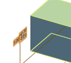
Wenn die Geometrie eines Bauteil geändert wird, werden alle zugehörigen Modelldefinitionen orange hervorgehoben:
-
Wenn ein Bauteil oder Part Studio über das Feature „Abgeleitet“ wird, sind alle Modelldefinitionen schreibgeschützt und können nicht bearbeitet werden. Sie können Beschriftungen weiterhin verschieben und gesteuerte Bemaßungen werden immer noch aktualisiert, wenn die abgeleitete Geometrie geändert wird. Die zugrunde liegenden Modelldefinitionen können jedoch nur im Quell-Part-Studio angepasst und dann im Feature „Abgeleitet“ aktualisiert werden. Weitere Informationen finden Sie unter Abgeleitet.
-
Kommentare können zu toleranten Skizzenbemaßungen, Feature-Bemaßungen, Bohrungsbeschreibungen und Prüftabellen-Beschriftungen (Bemaßungen, Bezugspunkte, Form- und Lagetoleranzen) im Grafikbereich hinzugefügt und markiert werden. Weitere Informationen finden Sie unter Kommentare zu MBD-Beschriftungen hinzufügen.