 Prüftabelle
![]()
Verfügbar in: Part Studios
Prüfen und fügen Sie modellbasierte Definitionen zu Bauteilen im Part Studio hinzu. Dazu gehören Beschriftungen wie Bezugspunkte, Bemaßungen, Form- und Lagetoleranzen und Schweißsymbole. Beschriftungen können als parallel oder deckungsgleich mit Flächen eingestellt werden. Der Beschriftungstext lässt sich an Flächen oder Kanten ausrichten. Die Tabelle kann auch als CSV-Datei exportiert werden.
In einem Part Studio können Sie in der Prüftabelle MBD-Daten anzeigen, hinzufügen und exportieren.
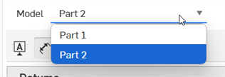
Sind mehrere Bauteile mit einer modellbasierten Definition im Part Studio vorhanden, legen Sie über das Modell-Dropdown-Menü fest, für welches Bauteil oder zusammengesetzte Bauteil die Daten in der Prüftabelle angezeigt werden sollen.
Klicken Sie auf „Standardtoleranzen auswählen“, um die Bibliothek mit Standardtoleranzen zu durchsuchen. Oder wählen Sie eine Company-Bibliothek aus dem aktuellen Dokument oder anderen Dokumenten aus. Die Bibliothek mit den Onshape-Standardtoleranzen enthält einige Standardtoleranzen, die von Onshape verwaltet werden. Mit dieser Auswahl legen Sie die Standardtoleranzen für das aktuelle Part Studio fest.
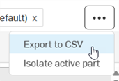
Klicken Sie auf das Überlaufmenü, um die Tabelle in eine CSV-Datei zu exportieren oder das aktiven Bauteil im Grafikbereich zu isolieren.
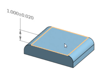
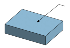
Fügen Sie während der Modellerstellung Informationen zur Produktherstellung hinzu, indem Sie Bemaßungen hinzufügen, Toleranzen anwenden und Beschriftungen zuweisen.
Fügen Sie in der ersten Skizze eine Bemaßung für die Linienlänge hinzu, indem Sie die beiden senkrechten Linien oder Endpunkte auswählen und zum Platzieren klicken. Toleranzoptionen sind für einzeilige Abstand-, Bogenlängen- und Mittellinienbemaßungen nicht verfügbar.
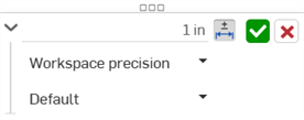
Klicken Sie im Bemaßungs-Dialogfenster auf das Symbol für Toleranzoptionen und dann auf den Dropdown-Pfeil, um einen Genauigkeits- und Toleranztyp auszuwählen.
Diese ursprünglich abgeleiteten Skizzenbemaßungen erscheinen nicht in der Eigenschaftentabelle, da kein Bauteil im Part Studio erstellt wurde und ihnen eine zugehörige Feature-Referenz fehlt.
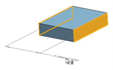
Starten Sie eine neue Extrusionsfunktion. Klicken Sie auf das Symbol für Toleranzoptionen für die Tiefe, um deren Wert zur Tabelle hinzuzufügen. Klicken Sie dann auf den Dropdown-Pfeil, um einen Genauigkeits- und Toleranztyp auszuwählen. Sobald das Feature erstellt ist, wird die Eigenschaftentabelle mit Daten ausgefüllt.
Ziehen Sie einen Dimensionswert, um ihn neu zu positionieren. Verwenden Sie die Zwangsbedingungen der Beschriftungs-Symbolleiste in der Prüftabelle, um Beschriftungen an Modellflächen auszurichten.
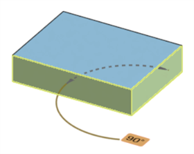
Um Bemaßungen im Modell neu zu positionieren, klicken Sie auf „Als deckungsgleich festlegen“. Wählen Sie eine Fläche für die Ausrichtung und dann mindestens eine Bemaßung aus. Mit „Parallel setzen“ wird die Beschriftung parallel zu einer Fläche ausgerichtet. Mit „Textausrichtung festlegen“ wird der Beschriftungstext an einer ausgewählten Kante oder Fläche ausgerichtet.
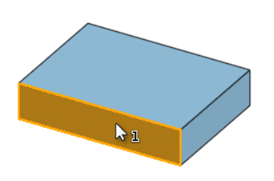
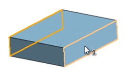
Beim Bemaßen werden ausgewählte Flächen der MBD-Referenz mit der Modellgeometrie verknüpft. So wird sichergestellt wird, dass die Definition im Modell selbst erfasst wird. Bemaßen Sie z. B. vom Skizzenpunkt bis zur Fläche des Modells und nicht von einer Modellkante oder einem Scheitelpunkt. Abgeleitete Skizzenbemaßungen wie diese haben keine Referenz in der Eigenschaftentabelle, bis sie in einem Feature verwendet werden.
Starten Sie ein neues Bohrungs-Feature. Legen Sie die Bohrungsparameter fest. Fügen Sie optional eine Toleranz zum Durchmesser hinzu. Der Skizzenabstand hat jetzt seine Referenz.
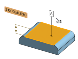
Nachdem Sie das Modell fertiggestellt haben, fügen Sie weitere Modelldefinitionen mithilfe der Beschriftungs-Symbolleiste hinzu.
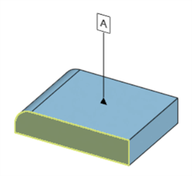
Klicken Sie auf das Bezugspunkt-Symbol. Wählen Sie eine Fläche aus und klicken Sie, um das Bezugspunkt-Symbol zu platzieren. Ziehen Sie das Basisdreieck, um es auf der Fläche neu zu positionieren. Ziehen Sie den Text des Bezugspunkts, um seine Position anzupassen.
Fügen Sie tolerante, gesteuerte Bemaßungen hinzu, die nicht in Skizzen oder Features erfasst wurden. Klicken Sie auf das Bemaßungssymbol. Wählen Sie die Fläche und dann die Bohrungsfläche aus. Klicken Sie, um sie zu platzieren. Gesteuerte Bemaßungen sind grau. Ihre Toleranzoptionen können nur bearbeitet werden, wenn die Prüftabelle geöffnet ist (nicht aus der Feature-Liste heraus). Doppelklicken Sie auf eine Bemaßung, um ihre Toleranzoptionen zu ändern.
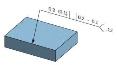
Fügen Sie Form- und Lagetoleranzen hinzu, um die Form, Ausrichtung und Position zu kontrollieren. Klicken Sie auf das Symbol für die Form- und Lagetoleranz. Wählen Sie das Symbol aus, geben Sie einen Toleranzwert ein und fügen Sie die Referenz-Bezugspunkte hinzu. Mit dem Plus-Symbol können Sie weitere Rahmen hinzufügen. Rechtsklicken Sie auf einen Rahmen und wählen Sie „Entfernen“ aus, um ihn zu löschen. Zeigen Sie Symbole an, um eines zu einem Textfeld hinzuzufügen. Klicken Sie auf eine Fläche oder Bemaßung, um den Rahmen anzufügen. Doppelklicken Sie darauf, um ihn zu bearbeiten.
Damit Ihr Team die Schweißanforderungen kennt, klicken Sie auf das Schweißsymbol. Legen Sie den Standard fest und definieren Sie den Schweißtyp. Wählen Sie eine Fläche aus und klicken Sie zum Platzieren. Ziehen Sie die Pfeilspitze, um sie auf der Fläche neu zu positionieren. Ziehen Sie das Schweißsymbol, um es zu verschieben. Doppelklicken Sie darauf, um es zu bearbeiten.
Weisen Sie für konfigurierte Bauteile Toleranzeinstellungen pro Konfiguration zu, sodass unabhängig generierte Bauteile ihre eigenen Toleranzdefinitionen beibehalten.
Die MBD ersetzt keine Zeichnungen, sondern dient als dynamischer Prüfungsplan, der die Informationen zur Produktfertigung (PMI) erfasst und für umfassendere nachgelagerte Zwecke erweitert.
Das Symbol für die Prüftabelle befindet sich rechts im Grafikbereich:
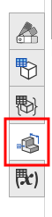
- Klicken Sie rechts im Grafikbereich (unter dem Ansichtswürfel) auf das Symbol „Prüfobjekt“ (
 ):
): 
-
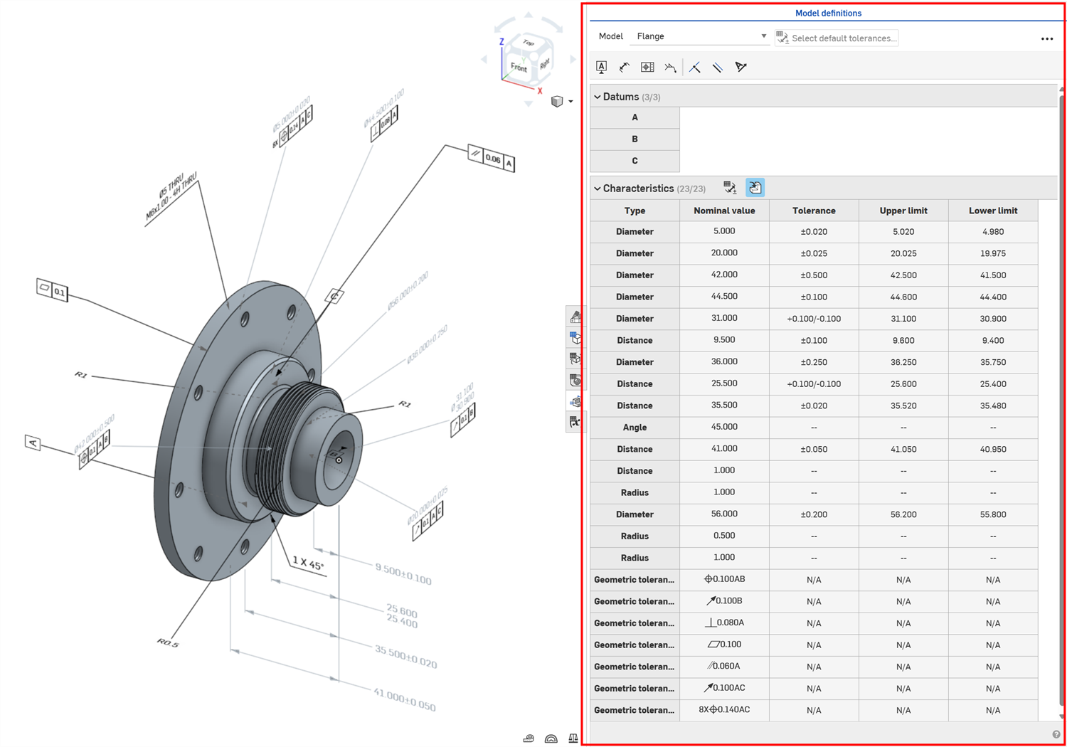
Die Prüftabelle wird geöffnet und zeigt oben den Titel der Modelldefinitionen.
Im Folgenden wird die Benutzeroberfläche der Prüftabelle erklärt:
-
Modell: Wählen Sie ein Bauteil im Grafikbereich aus, auf das Beschriftungen angewendet werden. Verwenden Sie das Dropdown-Menü, um zwischen den Bauteilen im Part Studio zu wechseln. Die nachstehenden Bezugspunkt- und Eigenschaftentabellen wechseln dann zur Modelldefinitionen für das ausgewählte Bauteil.
-
Standardtoleranzen auswählen (
 ): Klicken Sie auf diese Schaltfläche, um die Standardtoleranzen für das aktuelle Part Studio auszuwählen. Siehe Bibliothek mit Standardtoleranzen.
 -
Beschriftungs-Symbolleiste: Verwenden Sie die Optionen dieser Symbolleiste, um das ausgewählte Bauteil zu beschriften.
-
Bezugspunkt (
 ): Fügen Sie einen Bezugspunkt an einer bestimmten Position auf einer Fläche des ausgewählten Bauteils hinzu. Auf eine Fläche können mehrere Bezugspunkte angewendet werden. Siehe Bezugspunkt.
 -
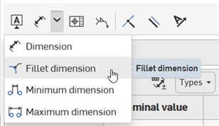
Bemaßung (
 ): Fügen Sie dem ausgewählten Bauteil eine gesteuerte Bemaßung hinzu. Siehe Bemaßung.
-
Verrundungsabmessung (
 ): Fügen Sie dem ausgewählten Bauteil eine gesteuerte Verrundungsabmessung hinzu. Siehe Verrundungsbemaßung.
 -
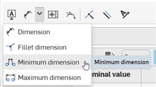
Minimale Bemaßung (
 ): Fügen Sie eine gesteuerte minimale horizontale, vertikale oder diagonale Abstandsbemaßung zwischen zwei zylindrischen Flächen auf dem ausgewählten Bauteil hinzu. Siehe Minimale Bemaßung.
 -
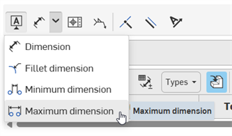
Maximale Bemaßung (
 ): Fügen Sie eine gesteuerte maximale horizontale, vertikale oder diagonale Abstandsbemaßung zwischen zwei zylindrischen Flächen auf dem ausgewählten Bauteil hinzu. Siehe Maximale Bemaßung.
-
-
Form- und Lagetoleranz (
 ):Gehört oft zu einem Bezugspunkt. Verwenden Sie die Form- und Lagetoleranz, um grundlegende Bemaßungsvermerke für das ausgewählte Bauteil zu erstellen und zu platzieren. Siehe Geometrische Toleranz.
 -
Schweißsymbol (
 ): Fügen Sie zur Fläche des ausgewählten Bauteil ein Schweißsymbol hinzu. Siehe Schweißsymbol.
 -
Als deckungsgleich festlegen (
 ): Damit wird die Anmerkung deckungsgleich mit der Fläche eines Bauteils. Siehe Als deckungsgleich festlegen.
 -
Parallel setzen (
 ): Damit legen Sie eine parallele Zwangsbedingung fest, um zwei oder mehr ausgewählte Bauteilelemente parallel anzuordnen. Siehe Parallel setzen.
 -
Textausrichtung festlegen (
 ): Stellen Sie den Beschriftungstext so ein, dass er an der Kante oder Fläche des Bauteils ausgerichtet wird. Siehe Textausrichtung festlegen.
-
-
Bezugspunkttabelle: enthält eine Zeile für jeden Bezugspunkt, der dem ausgewählten Bauteil zugeordnet ist.
-
Eigenschaftentabelle: enthält eine Zeile für jedes Prüfobjekt, das dem ausgewählten Bauteil zugeordnet ist. In den Spalten werden für jedes Prüfobjekt der Typ (Abstand, Fasenabstand,Radius, Verrundungsradius, Durchmesser, Winkel, Fasenwinkel, Form- und Lagetoleranz, Schweißsymbol), der Nominalwert, die Toleranz sowie der obere und untere Grenzwert angezeigt.
-
Filter: Mit den folgenden Optionen können Sie die Eigenschaftentabelle filtern. Nützlich für hochkomplexe Bauteile mit vielen Beschriftungen:
-
Standardtoleranzen anzeigen/ausblenden (
): Damit wenden Sie einen Filter auf die Eigenschaftentabelle an, um die Standardtoleranzen anzuzeigen oder auszublenden. -
Typen: Klicken Sie auf Typen, um ein Dropdown-Menü zu öffnen, in dem die Eigenschaftstypen ausgewählt werden. Bei Typen, die Sie in der Tabelle anzeigen möchten, markieren Sie das Kontrollkästchen. Sollen Typen in der Tabelle ausgeblendet werden, entfernen Sie das Häkchen aus dem Kontrollkästchen: Abstand, Winkel, Radius, Durchmesser, Fase, Verrundung, Bohrung, Schweißnaht und FLTol (Form- und Lagetoleranz). Sind alle Filter deaktiviert (Standard), wird alles angezeigt.
-
Abgeleitete Toleranzen anzeigen/ausblenden (
 ): Damit wenden Sie einen Filter auf die Eigenschaftentabelle an, um abgeleitete Toleranzen anzuzeigen oder ausblenden. Abgeleitete Toleranzen sind standardmäßig ausgeblendet.
 -
Filter zurücksetzen (
 ): Wenn die Filteroptionen von den Standardeinstellungen abweichen, klicken Sie auf Filter zurücksetzen, um die Filter auf die Standardeinstellungen zurückzusetzen:
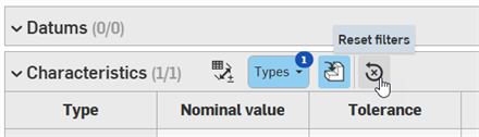
Derzeit werden Bohrungstoleranzen für abgeleitete Bauteile angezeigt, auch wenn der Filter so eingestellt ist, dass abgeleitete Toleranzen ausblenden werden sollten.
-
-
-
Klicken Sie auf das Bezugspunkt-Symbol (
) in der Beschriftungs-Symbolleiste. Das Dialogfeld Bezugspunkt wird geöffnet: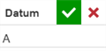
-
Klicken Sie auf dem Bauteil auf eine Flächenposition:
-
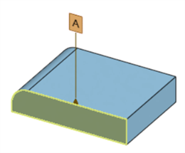
Ziehen Sie den Bezugspunkt, um die Hinweislinie zu verlängern, und den Bezugspunkt an einer bestimmten Stelle zu platzieren:
-
Optionally, edit the datum name in the Datum dialog. The first datum added to a part defaults to A, the next to B, then C, and so forth. The Datum name must be one or more uppercase letters followed by zero or more numbers. Spaces, hyphens, dashes, or special characters are not allowed. This field cannot be empty.
-
Klicken Sie zum Akzeptieren auf das Häkchen (
 ) oder auf „Abbrechen“ (
 ), um den Vorgang ohne Änderungen zu beenden.
Bezugstexte
-
Um ein Bezugspunkt zu bearbeiten, doppelklicken Sie darauf. Das Dialogfeld Bezugspunkt wird geöffnet. Nehmen Sie die erforderlichen Anpassungen vor.
-
Auf eine Fläche können mehrere Bezugspunkte angewendet werden.
All symbols from the spreadsheet Pete is sending
Anything else in a datum field will cause it to turn red but it will be accepted. The only thing that will kick out the users input is the character count going over 7.
Klicken Sie in der Beschriftungs-Symbolleiste auf das Symbol für Bemaßung (![]() ), um eine gesteuerte Bemaßung hinzuzufügen.
), um eine gesteuerte Bemaßung hinzuzufügen.
-
Klicken Sie auf eine Fläche auf dem Bauteil:
-
Klicken Sie auf eine zweite Fläche auf dem Bauteil:
-
Die Bemaßung ist erstellt. Ziehen Sie die Bemaßung, um ihre Hinweislinien bis zu einer bestimmten Position zu verlängern.
Im folgenden Beispiel erzeugt die Auswahl von zwei benachbarten Flächen eine gesteuerte Winkelbemaßung:
Bezugstexte
-
Ein gesteuerter Bemaßungswert kann nicht bearbeitet werden. Sie können jedoch die gesteuerte Bemaßungstoleranz mit der Umschaltfunktion aktivieren oder deaktivieren sowie ihre Toleranzoptionen bearbeiten (Arbeitsbereich-Genauigkeit und Toleranztyp).
-
Um die Toleranz einer beliebigen Bemaßung zu bearbeiten, doppelklicken Sie darauf. Das Dialogfenster für den Bemaßungskontext wird geöffnet. Nehmen Sie die erforderlichen Anpassungen vor:
-
Beschriftungen von gesteuerten Bemaßungen werden im Grafikbereich grau dargestellt. So können Sie sie leichter von steuernden Bemaßungen (schwarz) unterscheiden.
-
Das Bemaßen zwischen zwei zylindrischen Flächen ergibt einen gemessenen Abstand zwischen den Achsen beider Flächen. Um minimale oder maximale Abstände zu messen, verwenden Sie die Tools Minimale Bemaßung bzw. Maximale Bemaßung.
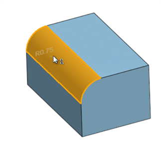
Erstellen Sie eine gesteuerte Radiusbemaßung für eine verrundete Fläche.
-
Klicken Sie in der Beschriftungs-Symbolleiste unter dem Dropdown-Menü Bemaßung auf das Symbol für Verrundungsbemaßung (
):
-
Klicken Sie auf eine verrundete Fläche auf dem Bauteil:
-
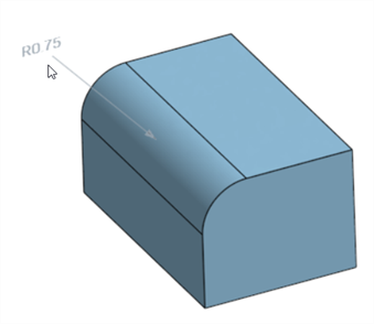
Die gesteuerte Radiusbemaßung wird zum Bauteil hinzugefügt. Ziehen Sie die Bemaßung, um ihre Hinweislinien bis zu einer bestimmten Position zu verlängern.
Bezugstexte
-
Ein gesteuerter Bemaßungswert kann nicht bearbeitet werden. Sie können jedoch die gesteuerte Bemaßungstoleranz mit der Umschaltfunktion aktivieren oder deaktivieren sowie ihre Toleranzoptionen bearbeiten (Arbeitsbereich-Genauigkeit und Toleranztyp).
-
Um die Toleranz einer beliebigen Bemaßung zu bearbeiten, doppelklicken Sie darauf. Das Dialogfenster für den Bemaßungskontext wird geöffnet. Nehmen Sie die erforderlichen Anpassungen vor:
-
Beschriftungen von gesteuerten Bemaßungen werden im Grafikbereich grau dargestellt. So können Sie sie leichter von steuernden Bemaßungen (schwarz) unterscheiden.
-
Eine Verrundungsbemaßung kann nicht zu einer ebenen Fläche oder einem Durchmesser (wie einem Rohr oder einer Leitung) hinzugefügt werden, sondern nur zu partiellen Zylindern, die z. B. mit dem Verrundungs-Feature erstellt wurden.
Erstellen Sie eine gesteuerte Mindestabstandsbemaßung zwischen zwei zylindrischen Flächen.
-
Klicken Sie in der Beschriftungs-Symbolleiste unter dem Dropdown-Menü Bemaßung auf das Symbol für Minimale Bemaßung (
):
-
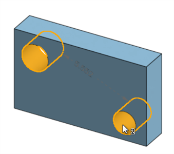
Klicken Sie auf die zwei zylindrischen Flächen auf dem Bauteil:
-
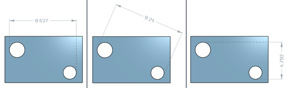
Die gesteuerte minimale Bemaßung wird zum Bauteil hinzugefügt. Ziehen Sie die Bemaßung, um ihre Hinweislinien bis zu einer bestimmten Position zu verlängern. Während Sie das Bauteil bewegen, werden Optionen für die horizontalen, diagonalen und vertikalen Abstände angezeigt.
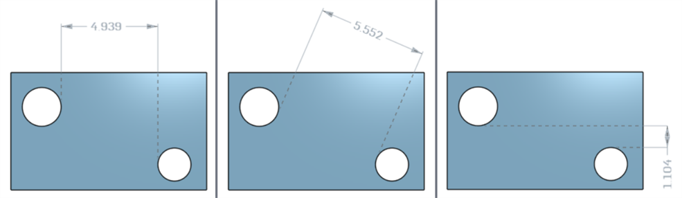
Von links nach rechts: horizontale, diagonale und vertikale Mindestabstandsbemaßungen.
-
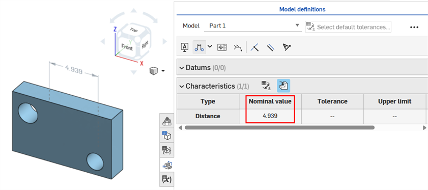
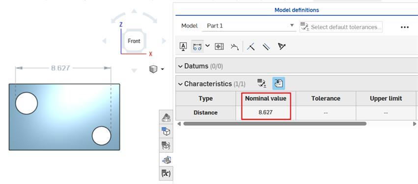
Sobald Sie geklickt haben, um die Hinweislinien zu platzieren, wird der Mindestbemaßungsabstand festgelegt, und sein Wert wird in der Eigenschaftentabelle als Nominalwert angezeigt:
-
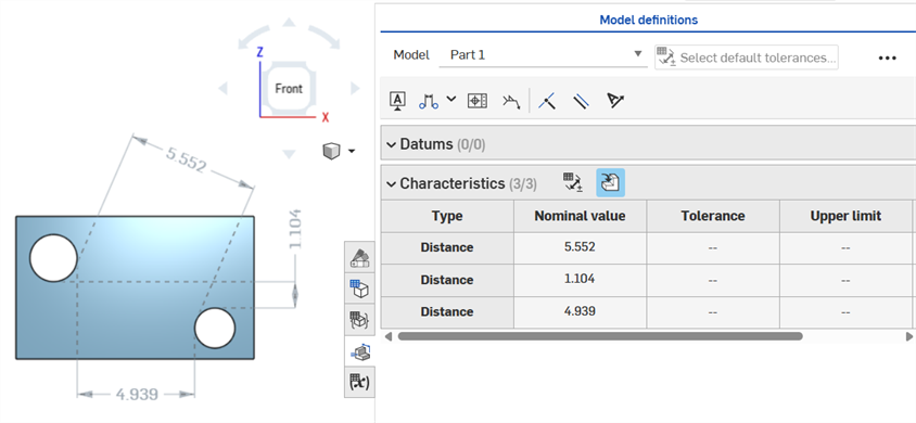
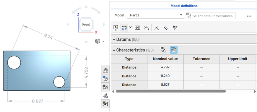
(Optional) Falls erforderlich, können alle drei minimalen Bemaßungen (horizontal, diagonal und vertikal) zum selben Zylindersatz hinzugefügt werden. Wiederholen Sie die Schritte 1–3, um die erforderliche minimale Bemaßung hinzuzufügen. Alle drei Abstandswerte werden in der Eigenschaftentabelle angezeigt:
Bezugstexte
-
Ein gesteuerter Bemaßungswert kann nicht bearbeitet werden. Sie können jedoch die gesteuerte Bemaßungstoleranz mit der Umschaltfunktion aktivieren oder deaktivieren sowie ihre Toleranzoptionen bearbeiten (Arbeitsbereich-Genauigkeit und Toleranztyp).
-
Um die Toleranz einer beliebigen Bemaßung zu bearbeiten, doppelklicken Sie darauf. Das Dialogfenster für den Bemaßungskontext wird geöffnet. Nehmen Sie die erforderlichen Anpassungen vor:
-
Beschriftungen von gesteuerten Bemaßungen werden im Grafikbereich grau dargestellt. So können Sie sie leichter von steuernden Bemaßungen (schwarz) unterscheiden.
Erstellen Sie eine gesteuerte maximale Abstandsbemaßung zwischen zwei zylindrischen Flächen.
-
Klicken Sie in der Beschriftungs-Symbolleiste unter dem Dropdown-Menü Bemaßung auf das Symbol für Maximale Bemaßung (
):
-
Klicken Sie auf die zwei zylindrischen Flächen auf dem Bauteil:
-
Die gesteuerte maximale Bemaßung wird zum Bauteil hinzugefügt. Ziehen Sie die Bemaßung, um ihre Hinweislinien bis zu einer bestimmten Position zu verlängern. Während Sie das Bauteil bewegen, werden Optionen für die horizontalen, diagonalen und vertikalen Abstände angezeigt.
Von links nach rechts: horizontale, diagonale und vertikale maximale Abstandsbemaßungen.
-
Sobald Sie klicken, um die Hinweislinien zu platzieren, wird der maximale Bemaßungsabstand festgelegt, und sein Wert wird in der Eigenschaftentabelle als Nominalwert angezeigt:
-
(Optional) Falls erforderlich, können alle drei maximalen Bemaßungen (horizontal, diagonal und vertikal) zum selben Zylindersatz hinzugefügt werden. Wiederholen Sie die Schritte 1–3, um die erforderliche maximale Bemaßung hinzuzufügen. Alle drei Abstandswerte werden in der Eigenschaftentabelle angezeigt:
Bezugstexte
-
Ein gesteuerter Bemaßungswert kann nicht bearbeitet werden. Sie können jedoch die gesteuerte Bemaßungstoleranz mit der Umschaltfunktion aktivieren oder deaktivieren sowie ihre Toleranzoptionen bearbeiten (Arbeitsbereich-Genauigkeit und Toleranztyp).
-
Um die Toleranz einer beliebigen Bemaßung zu bearbeiten, doppelklicken Sie darauf. Das Dialogfenster für den Bemaßungskontext wird geöffnet. Nehmen Sie die erforderlichen Anpassungen vor:
-
Beschriftungen von gesteuerten Bemaßungen werden im Grafikbereich grau dargestellt. So können Sie sie leichter von steuernden Bemaßungen (schwarz) unterscheiden.
-
Klicken Sie in der Beschriftungs-Symbolleiste auf das Symbol für die Form- und Lagetoleranz (
). Das Dialogfenster Form- und Lagetoleranz wird geöffnet: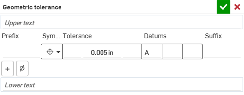
-
Sie haben folgende Optionen:
-
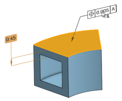
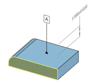
Klicken Sie auf eine Flächenposition auf dem Bauteil, um der Fläche die Form- und Lagetoleranz zuzuweisen.
Ziehen Sie die Form- und Lagetoleranz, um die Toleranz und die Hinweislinie bis zu einer bestimmten Position im Grafikbereich zu erweitern.
Klicken Sie mit der linken Maustaste, um die Form- und Lagetoleranz zu platzieren:
-
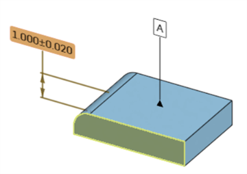
Klicken Sie auf eine Bemaßung auf dem Bauteil, um die Form- und Lagetoleranz an diese Bemaßung anzufügen.
Ziehen Sie die Bemaßung und die Form- und Lagetoleranz als Gruppe gemeinsam, um sie an einer bestimmten Position im Grafikbereich zu platzieren.
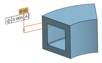
Die Form- und Lagetoleranz kann während der Erstellung oder nach dem Schließen des Dialogfensters „Form- und Lagetoleranz“ im Grafikbereich verschoben werden.
-
-
Geben Sie die Spezifikationen für die Form- und Lagetoleranz in das Dialogfenster Form- und Lagetoleranz ein:

-
Upper/Lower text field - Add information above or below the Geometric tolerance. The Upper text field allows up to 50 characters. The Lower text field allows up to 200 characters.
-
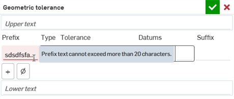
Prefix/Suffix - Enter a Prefix or Suffix to add information to the left or right of the Geometric tolerance frame, respectively. Both fields allow up to 20 characters.
-
Toleranzrahmen
- Symbol (Art der Form- und Lagetoleranz): Wählen Sie aus diesem Dropdown-Feld die Art der Form- und Lagetoleranz aus. Das Symbol befindet sich links neben der Form- und Lagetoleranz. Die Optionen sind: Position, Konzentrizität, Symmetrie, Parallelität, Rechtwinkligkeit, Winkligkeit, Zylindrizität, Ebenheit, Rundheit, Geradheit, Profil (Oberfläche), Profil (Linie), kreisförmiger Rundlauf und Gesamtlauf..
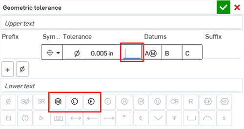
- Tolerance - Enter a tolerance value. Optionally, enter symbols in fields to the left and/or right of the tolerance value. Both left/right fields allow up to 7 symbols. Non-allowable symbols can be added here and are accepted, but not recommended.
- Datums - Enter up to 3 datum values in the 3 Datum fields. Each field must start with at least one uppercase letter, and then symbols can be added in using the Symbols palette (see Show/Hide symbols below). Hyphens are also accepted in this field.
- Rahmen hinzufügen: Klicken Sie auf das Symbol für Rahmen hinzufügen (
 ), um zur Tabelle eine zusätzliche Zwangsbedingungszeile hinzuzufügen. Bis zu fünf Zwangsbedingungen können zur Form- und Lagetoleranz hinzugefügt werden. Ändern Sie das untere Symbol in „Zusammengesetzt“, um einen zusammengesetzten Rahmen zu erstellen.
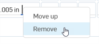
 Um eine Zwangsbedingungslinie zu verschieben oder zu entfernen, rechtsklicken Sie auf eine beliebige Zelle in dieser Zeile und wählen entweder Nach oben/unten aus (um die Zwangsbedingung eine Zeile in der Tabelle nach oben oder unten zu verschieben) oder Entfernen (um die Zwangsbedingungszeile aus der Tabelle zu entfernen). Dies kann nur für zusätzliche Zwangsbedingungszeilen durchgeführt werden.
- Symbole anzeigen/ausblenden: Klicken Sie auf das Symbol für Symbole anzeigen (ø), um eine Tabelle mit Symbolen zu öffnen, die in die Felder für die Form- und Lagetoleranz eingefügt werden können. Im oberen und unteren Textfeld sowie im Präfix- und Suffix-Feld sind alle Symbole verfügbar:
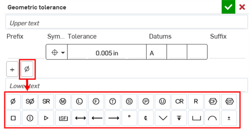
Wenn Sie sich in einem Feld innerhalb des Toleranzrahmens befinden, bestimmt die Kombination aus geometrischem Symboltyp und einem bestimmten Feld, welche Symbole verwendet werden können. Zum Beispiel sind in dem Feld nach dem Toleranzwert die folgenden Symboloptionen verfügbar:
-
-
Klicken Sie zum Akzeptieren auf das Häkchen (
) oder auf „Abbrechen“ (), um den Vorgang ohne Änderungen zu beenden.
Bezugstexte
-
Um eine beliebige Form- und Lagetoleranz zu bearbeiten, doppelklicken Sie auf die Toleranz. Das Dialogfenster Form- und Lagetoleranz wird geöffnet. Nehmen Sie die erforderlichen Anpassungen vor.
-
Einer Fläche können mehrere Form- und Lagetoleranzen zugeordnet werden, einer Bemaßung aber nur eine einzige.
-
A field with an incorrect entry is highlighted red. A tooltip explains why the field is in error. For example, if the Prefix field has over 20 characters, as shown below:
-
Klicken Sie auf das Schweißsymbol (
) in der Annotations-Symbolleiste. Das Dialogfenster Schweißsymbol wird geöffnet: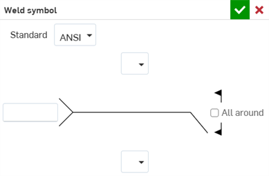
-
Klicken Sie auf eine Fläche auf dem Bauteil, um das Schweißsymbol zu platzieren.
-
Ziehen Sie das Schweißsymbol, um es und seine Hinweislinie bis zu einer bestimmten Position zu verlängern:
-
Geben Sie die Spezifikationen für das Schweißsymbol im Dialogfenster Schweißsymbol ein:
-
Norm: Wählen Sie entweder ANSI oder ISO aus.
-
Identifikationslinie umkehren (nur ISO-Norm): Wenn diese Option aktiviert ist, wird die Schweißidentifikationslinie in die entgegengesetzte Richtung umgekehrt.
-
Schweißtyp (oberer oder unterer): Wählen Sie aus den folgenden Schweißtypen aus: Keine, Vierkant-Nut, V-Nut, U-Nut, J-Nut, Schrägnut, einfache HY-Nut, breit, V-Bördelnut, Schräge Bördelnut, Nahtstoß, Kehlnaht, Loch- oder Schlitznaht, Fugenschweißverbindung oder Punktschweißverbindung.
-
Nut (obere oder untere): Geben Sie den Grad für die Nut zwischen 0 und 360 ein.
-
Spaltbreite (obere oder untere): Geben Sie den Abstand für die Spaltbreite in den angegebenen Maßeinheiten ein.
-
Bearbeitung (obere oder untere; nur ANSI-Norm): Wählen Sie aus den folgenden Bearbeitungen aus: Keine, C – Spanen, G – Schleifen, H – Hämmern, M – Maschinell bearbeiten, R – abgenutzt oder U – nicht spezifiziert.
-
Kontur (obere oder untere): Wählen Sie aus den folgenden Konturen aus: Keine, Flach, Konvex oder Konkav.
-
Schweißgröße (obere oder untere): Geben Sie die Schweißnahtgröße als Abstandsmessung ein.
-
Schweißtiefe (oben oder unten): Geben Sie die Schweißtiefe als Abstandsmessung ein.
-
Schweißlänge (obere oder untere): Geben Sie die Schweißnahtlänge als Abstandsmessung ein.
-
Schweißabstand (oberer oder unterer): Geben Sie den Schweißabstand als Abstandsmessung ein.
-
Reference - Enter the weld reference. Up to 100 characters are allowed.
-
- Klicken Sie zum Akzeptieren auf das Häkchen () oder auf „Abbrechen“ (), um den Vorgang ohne Änderungen zu beenden.
Bezugstexte
-
Um ein beliebiges Schweißsymbol zu bearbeiten, doppelklicken Sie darauf. Das Dialogfenster Schweißsymbol wird geöffnet. Nehmen dort alle Anpassungen vor.
-
Eine Fläche kann mit mehreren Schweißsymbolen versehen werden.
-
Klicken Sie in der Beschriftungs-Symbolleiste auf das Symbol Als deckungsgleich festlegen (
). -
Wählen Sie eine Bauteilfläche aus:
-
Wählen Sie die Beschriftung aus. Die Beschriftung ist deckungsgleich mit der Kante der Fläche festgelegt:
Bezugstexte
-
Wenn eine Fläche ausgewählt ist, klicken Sie auf zusätzliche Beschriftungen, damit sie alle mit der ausgewählten Fläche deckungsgleich sind.
-
Flächen, die durch eine Fase oder Verrundung erzeugt wurden, können zwar ausgewählt werden, aber nicht mit Beschriftungen als deckungsgleich festgelegt werden.
-
Klicken Sie in der Beschriftungs-Symbolleiste auf das Symbol für Parallel setzen (
). -
Wählen Sie eine Bauteilfläche aus:
-
Wählen Sie die Beschriftung aus. Die Beschriftung wird parallel zur Fläche festgelegt:
Wenn eine Fläche ausgewählt ist, klicken Sie auf zusätzliche Beschriftungen, um sie parallel zur ausgewählten Fläche zu setzen.
-
Klicken Sie in der Beschriftungs-Symbolleiste auf das Symbol für Textausrichtung festlegen (
). -
Wählen Sie die Kante oder Fläche des Bauteils aus:
-
Wählen Sie die Beschriftung aus. Der Beschriftungstext wird an der ausgewählten Kante oder Fläche ausgerichtet:
Wenn eine Kante oder Fläche ausgewählt ist, klicken Sie auf zusätzliche Beschriftungen, um ihren Text an der ausgewählten Kante/Fläche ausrichten.
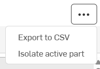
Klicken Sie oben rechts in der Tabelle auf das Symbol für das Überlaufmenü (![]() ), um auf die folgenden Optionen zuzugreifen:
), um auf die folgenden Optionen zuzugreifen:
-
Als CSV exportieren: exportiert die Tabelle als CSV-Datei für Tabellenkalkulationsprogramme wie Microsoft Excel oder Google Sheets. Weitere Informationen finden Sie unter Modell-Prüftabelle exportieren.
-
Aktives Bauteil isolieren/Gesamtes Part Studio anzeigen: isoliert das aktuell aktive Modell. Wenn ausgewählt, wird das Dialogfenster Isolieren geöffnet, in dem Sie die Isolierung genauer festlegen können.
Wenn das Dialogfenster noch geöffnet ist, wird beim Zugriff auf diese Optionen über das Überlaufmenü die Option Gesamtes Part Studio anzeigen angezeigt. Wenn Sie diese Option wählen, wird das Dialogfeld „Isolieren“ geschlossen und alle Bauteile im Part Studio werden sichtbar.
Wenn einer Beschriftung in der Prüftabelle ein Kommentar zugeordnet ist, wird rechts neben dem Bezugspunkt in der Datumstabelle ein Kommentarindikator oder in der Eigenschaftentabelle ein Typ angezeigt:
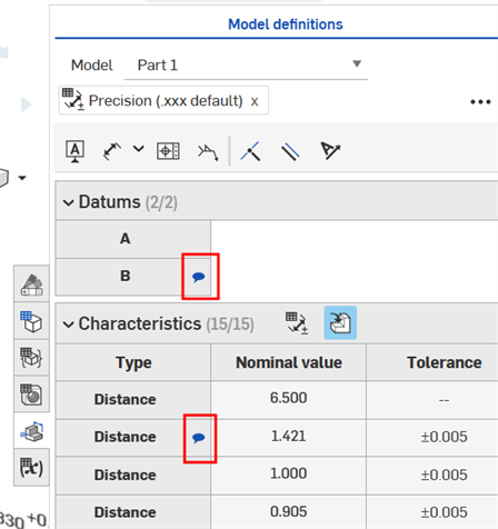
Weitere Informationen finden Sie unter Kommentare zu MBD-Beschriftungen hinzufügen.
Im Folgenden wird die Quermarkierung aus der Prüftabelle erklärt.
-
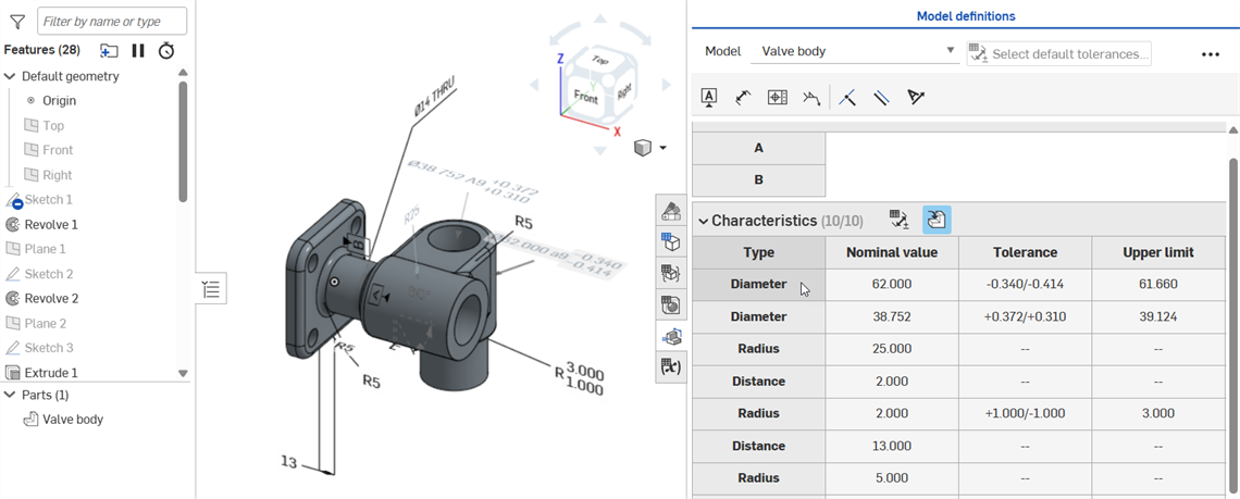
Wenn Sie den Mauszeiger über ein Bezugspunkt oder Zellen mit Werten in der Eigenschaftentabelle bewegen (zum Beispiel in den Spalten „Nominalwert“, „Toleranz“ oder „Ober-/Untergrenze“), werden der Umriss der zugehörigen Fläche(n) im Grafikbereich (orange), alle zugehörigen Bezugsbeschriftungen sowie steuernde oder gesteuerte Bemaßungen mit einer Quermarkierung hervorgehoben:
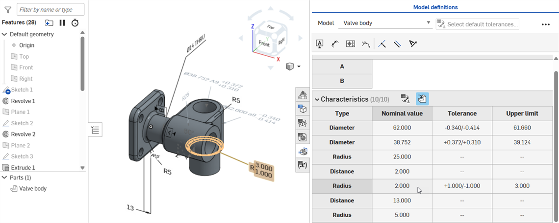
Zeigen Sie mit der Maus auf die Nominalwert-Zelle einer steuernden Bemaßung.
Zeigen Sie mit der Maus auf die Nominalwert-Zelle einer gesteuerten Bemaßung.
-
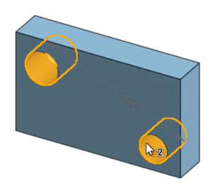
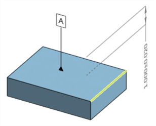
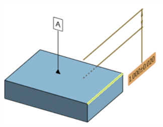
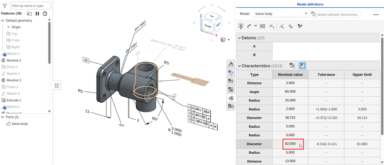
Wenn Sie auf eine Bezugspunkt- oder Typ-Zelle klicken (zum Beispiel „Abstand“, „Durchmesser“ oder „Radius“), werden die zugehörigen Flächen im Grafikbereich (gelb), das Bauteil in der Bauteilliste sowie die zugehörige Bemaßung oder Beschriftung (ob steuernd oder gesteuert) und alle zugehörigen Features in der Feature-Liste hervorgehoben:
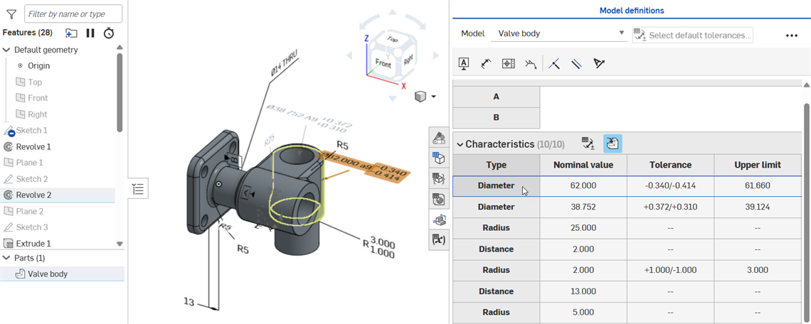
Wenn Sie auf die Durchmesser-Zelle klicken, wird die zugehörige Fläche im Grafikbereich, das Bauteil in der Bauteilliste (Ventilkörper) sowie die gesteuerte Bemaßung (Durchmesser) und das Feature in der Feature-Liste (Rotieren 2) markiert.
-
Die Bezugspunkt- und Typ-Zellen haben eine Umschaltfunktion. Durch erneutes Klicken wird die Quermarkierung aufgehoben:
-
Die folgende Abbildung zeigt eine gefaste Kante. Wenn Sie im Grafikbereich auf die Abstandsbemaßung klicken, wird als Quermarkierung eine Fläche hervorgehoben, wenn Gleicher Abstand als Fasentyp (linkes Bild) ausgewählt ist. wenn Zwei Abstände als Fasentyp ausgewählt ist (mittleres Bild), werden zwei Flächen hervorgehoben. Wenn Sie auf die Winkelbemaßung klicken, werden zwei Flächen als Quermarkierung hervorgehoben, wenn Abstand und Winkel als Fasentyp ausgewählt sind (rechtes Bild).
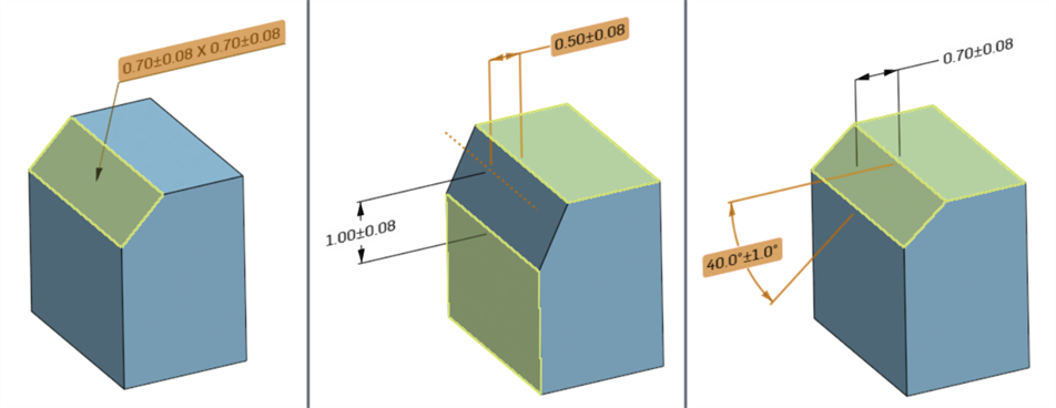
Hervorhebung, wenn eine Bemaßung im Grafikbereich ausgewählt ist: „Gleicher Abstand“ (links), „Zwei Abstände“ –wenn „Abstand 1“ ausgewählt ist (Mitte) –, „Abstand und Winkel“ – wenn „Winkel“ ausgewählt ist (rechts)
Wenn Sie eine Bemaßung im Grafikbereich auswählen (Winkel im Beispiel unten), wird die Bemaßung in der Prüftabelle ebenfalls blau umrandet und jedes zugehörige Feature in der Feature-Liste sowie Bauteile in der Bauteilliste wird als Quermarkierung hervorgehoben:
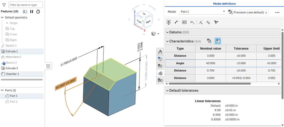
Der Mauszeiger muss von der Zelle weg und dann wieder über die Zelle bewegt werden, um die Quermarkierung anzuzeigen, nachdem die Auswahl aufgehoben wurde.
Die Prüftabelle jedes Modells kann in eine geordnete CSV-Datei mit einer Liste aller Abmessungen und Beschriftungen des Modells exportiert werden:
- Wählen Sie das Modell aus der Dropdown-Liste Modell aus:
- Klicken Sie oben rechts in der Prüftabelle auf die Schaltfläche für das Überlaufmenü (
 ).
). - Wählen Sie „Als CSV exportieren“ aus:
-
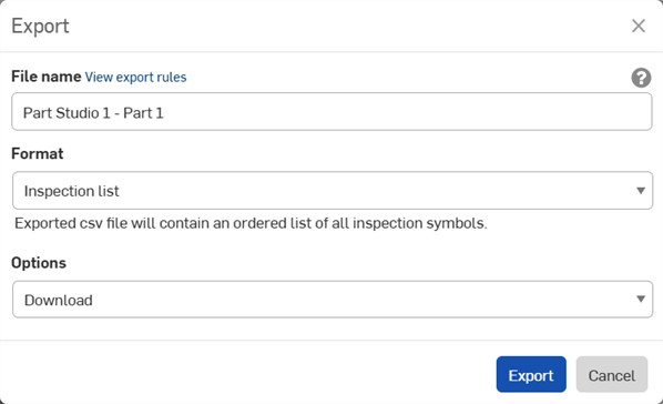
Das Dialogfenster „Exportieren“ wird geöffnet. Wählen Sie aus den folgenden Optionen aus:
-
Dateiname: Standardmäßig ist der Dateiname der Name der Registerkarte des Part Studios und des Modells, das im 1. Schritt ausgewählt wurde. Optional können Sie diesen Namen mit dem gewünschten Dateinamen überschreiben.
-
Format: Das Ausgabeformat. Standardmäßig ist Prüfliste ausgewählt. Lassen Sie diese Option ausgewählt.
- Optionen: Wählen Sie eine der folgenden Optionen aus:
Herunterladen: lädt die Datei auf Ihren Computer herunter.
Datei herunterladen und in neuer Registerkarte speichern: lädt die Datei auf Ihren Computer herunter und erstellt außerdem eine neue Registerkarte im aktuellen Dokument, wo die Datei gespeichert wird.
E-Mail mit Datei-Download-Link: Senden Sie die exportierte Datei als Download-Link per E-Mail (d. h. bei allen Abo-Arten außer Free- und Education-Abos). Siehe Abschnitt Exportieren via E-Mail mit Datei-Download-Link unten.
Datei in neuer Registerkarte speichern: erstellt eine neue Registerkarte im aktuellen Dokument, wo die Datei gespeichert wird.
Der Download-Ort ist browserspezifisch. Wenn Sie aufgefordert werden möchten, eine Datei an einem anderen Speicherort zu speichern, suchen Sie in Ihren Browser-Einstellungen nach der Option „Vor dem Herunterladen nach dem Speicherort der einzelnen Dateien fragen“.
-
- Wenn Sie die Datei auf Ihren Computer heruntergeladen haben, können Sie sie in einer Tabellenkalkulationsanwendung wie Microsoft Excel (siehe Bild unten) mit den Spalten „Beschriftungsart“, „Nominalwert“, „Toleranz“, „Oberer Grenzwert“ und „Unterer Grenzwert“ öffnen:
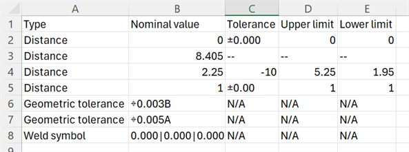
Einige Tabellenkalkulationsanwendungen berechnen automatisch Symbole oder formatieren sie neu, einschließlich Klammern sowie positiver und negativer Toleranzsymbole. Wenn die erwarteten Ergebnisse in die Tabelle übernommen werden, müssen Sie die Daten möglicherweise neu formatieren oder einen Texteditor anstelle eines Tabellenkalkulationseditors verwenden.
Exportieren via E-Mail mit Datei-Download-Link
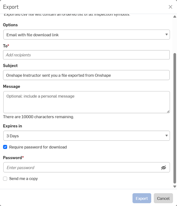
Bei jedem Export haben Sie die Möglichkeit, die exportierte Datei als Link zu versenden (Free- und Education-Abos ausgenommen). Wenn Sie sich im Dialogfenster „Exportieren“ befinden:
-
Wählen Sie E-Mail mit Datei-Download-Link unter dem Dropdown-Menü Optionen aus:
-
Geben Sie die folgenden E-Mail-Optionen ein:
-
An: E-Mail-Adresse des Empfängers (erforderlich).
-
Betreff: Ihre individuelle Betreffzeile für die E-Mail.
-
Nachricht: eine optionale Nachricht.
-
Läuft ab in: gibt an, wie lange der Download-Link verfügbar sein soll. Standardeinstellung: 3 Tage.
-
Passwort für den Download erforderlich: Aktivieren Sie diese Option, um den Link, den Sie per E-Mail versenden, mit einem Passwort zu schützen.
-
Passwort: Wenn „Passwort für den Download erforderlich“ aktiviert ist, geben Sie ein Passwort in dieses Feld ein. Dies ist das Passwort zum Öffnen der per E-Mail gesendeten Datei.
-
Kopie an mich: sendet eine Kopie der E-Mail an Ihre E-Mail-Adresse (die des Autors).
-
Senden Sie niemals ein Passwort per E-Mail. Es ist besser, in der Nachricht anzugeben, dass der Empfänger Sie auf anderem Wege kontaktieren soll, um das Passwort zu erhalten.
Der Empfänger erhält eine E-Mail von Onshape mit dem Link zum Herunterladen der exportierten Prüftabelle.