Viewing Models with AR View
![]()
AR view is an Onshape feature enabling you to view models in a physical environment through the use of augmented reality. In this viewing mode, you can place and view a model (part or assembly) in your physical space.
AR view is supported when using Onshape on an iOS platform. It is available in Part Studios and Assemblies.
AR view is view only. The model cannot be edited. You can, however, place the model in the viewing area, and rotate and view the model from all sides, as well as see shadows under the models.
Accessing AR view in a Part Studio
Make sure that Onshape has permissions to use the device camera. With a part in a Part Studio:
-
Tap the View cube.
-
Select AR view from the list of options.
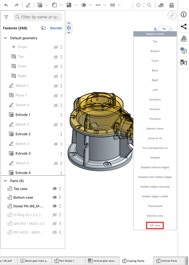
-
With AR view enabled, you see whatever the camera is pointed at. Move the device so that a flat surface comes into view. The model's bottom plane is used to orient the model on top of the surface. The ground plane is indicated by a light blue box outline.
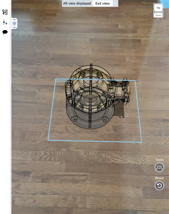
-
Tap a location in the view at which to place the part. When placed, the ground plane indicator disappears.
-
Pan with two fingers to rotate the part in place.
-
Pinch your fingers in and out to zoom in and out.
-
Tap and drag to translate the object's position.
-
Double-tap to reset the part in AR view.
-
From the Features list, click the eye icon (
 ) next to any part to toggle its visibility (show/hide).
 -
Click the three-dot menu to Hide other sketches (from the Features list) or Hide other parts (from the Parts list).
-
If the Part Studio has configurations, they are visible above the Features list in AR view. You can select from any of the existing configurations.
-
-
Click the Tools button to access the following menu options:
-
Save image to photos - Saves the current view to the Photos application on your mobile device.
-
Review AR gestures - Opens a banner along the bottom of the screen to review the AR gestures that can be used on-screen.
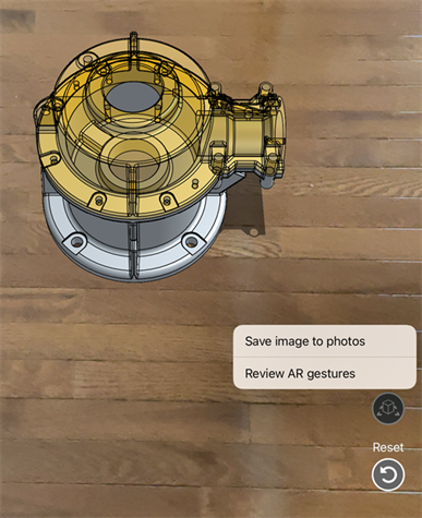
-
-
Click the Reset button to reset the positioning in the event you want to reset placement of the model.
-
When finished viewing the part in the AR view, tap Exit View at the top of the window or the command in the View cube menu.
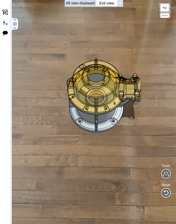
Accessing AR view in an Assembly
Make sure that Onshape has permissions to use the device camera. With a part or assembly in an Assembly:
-
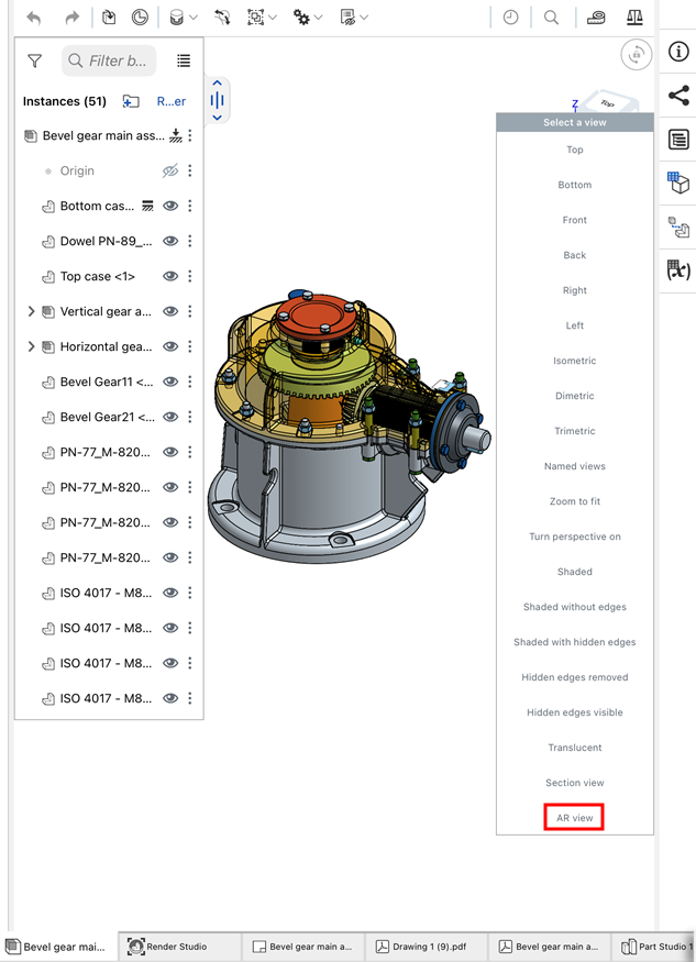
Tap the View cube.
-
Select AR view from the list of options.
-
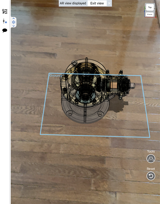
With AR view enabled, you see whatever the camera is pointed at. Move the device so that a flat surface comes into view. The model's bottom plane is used to orient the model on top of the surface. The ground plane is indicated by a light blue box outline.
-
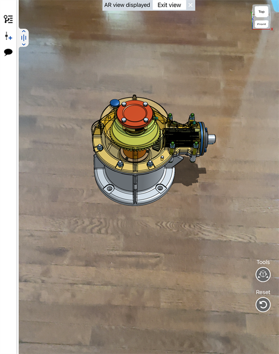
Tap a location in the view at which to place the part or assembly. When placed, the ground plane indicator disappears.
-
Pan with two fingers to rotate the part in place.
-
Pinch your fingers in and out to zoom in and out.
-
Tap and drag to translate the object's position.
-
Double-tap to reset the part in AR view.
-
From the Instances list, click the eye icon (
 ) next to any instance to toggle its visibility (show/hide).
 -
Click the three-dot menu to Hide other instances, Hide all instances, or show all instances (if there are hidden instances).
-
If the Assembly has configurations, they are visible above the Instances list in AR view. You can select from any of the existing configurations.
-
-
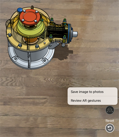
Click the Tools button to access the following menu options:
-
Save image to photos - Saves the current view to the Photos application on your mobile device.
-
Review AR gestures - Opens a banner along the bottom of the screen to review the AR gestures that can be used on-screen.
-
-
Click the Reset button to reset the positioning in the event you want to reset placement of the model.
-
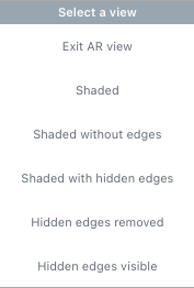
When finished viewing in the AR view, tap Exit View at the top of the window or select the Exit AR view option in the View cube menu:
Section view
Create a section view by placing a cutting plane line and specifying a direction. To create a section view while in AR view:
-
After placing a part, select a plane, planar mate, or Mate connector.
-
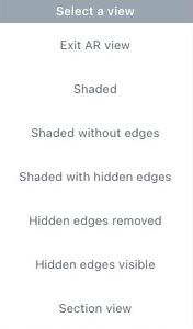
Tap the View cube in the upper right corner of the graphics area, then select Section view from the menu:
-
A drag manipulator appears on the selected plane, planar mate, or Mate connector. Use this to adjust the appearance of the section view.
-
To turn Section view off, tap the View cube again and select Turn off Section view.
Using AR to snap model geometry to real-world geometry
You can also snap modeled geometry to real-world geometry by importing the real-world environment into a Part Studio as a composite part.
-
Import the environment using the Import from Scan option.
-
In the model Document, either:
-
Once aligned, use AR View to detect the scanned area in real-world space. The model is placed according to the Part Studio's position and orientation or its configured placement in the Assembly.
Tips
-
Use Reset (in the lower right of the device screen) to restart the placement of the part.
-
Use Gestures (in the lower right of the device screen) to display instructions on using mobile gestures in AR view.
-
For users with View only permissions, you can still view models using AR view in the toolbar.