View Context Menu


Available in: Drawing
Hover over any view and right-click the mouse to open a context menu on any view to access a list of command options for that view. These command options are listed below. Not all options listed here are available for every type of view.
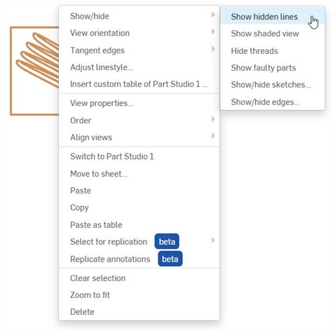
Example of a typical view context menu
 Show/hide options
Allows you to show/hide various elements from the drawing view. Not all options are available for all views, and some options depend on elements in the view itself. For example, hide/show centerlines is not available if the view does not contain circular geometry.
Show/hide hidden lines
By default, the lines of a view that are not visible in the current view position (hidden lines) are hidden.
To toggle their visibility, right-click on the view and select Show/hide > Show hidden lines or Hide hidden lines from the context menu:
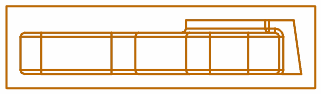
The resultant view:
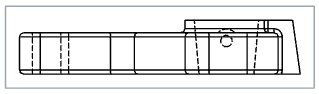
Show/hide bend lines
By default, bend lines of a sheet metal flat pattern view are visible.
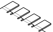
To toggle their visibility, right-click on the view and select Show/hide > Show bend lines or Hide bend lines from the context menu:
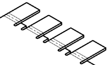
The resultant view:
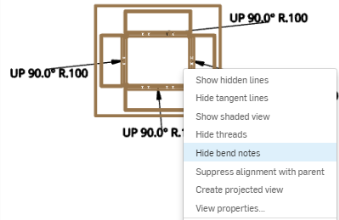
Show/hide bend notes
From an section view, you can toggle the visibility of bend notes for flattened views of sheet metal by right-clicking on the view and selecting Show/hide > Show bend notes or Hide bend notes from the context menu:
Show/hide shaded view
By default, the shaded view of parts is not visible.
To toggle their visibility, right-click on the view and select Show/hide > Show shaded view or Hide shaded view from the context menu:
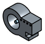
If a parent view is shaded, then the Detail view will also be shaded. You can change the shading independently of the parent, and also the parent independently of the child (right-click on the view).
If a Decal is applied to a part, it is only visible when the shaded view is shown.
Show/hide threads
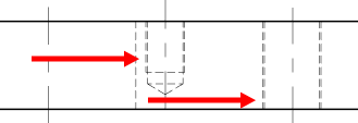
By default, lines indicating threaded holes are visible.
To toggle their visibility, right-click on the view and select Show/hide > Show or Hide threads from the context menu:
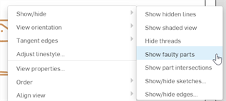
Show/hide faulty parts
Show or hide faulty parts that have been inserted into an assembly drawing view. Faulty parts are shown by default in Part drawings, but they are hidden by default in assembly drawings; rendering them may impact performance.
To toggle the visibility of faulty parts, right-click on the view and select Show/hide > Show faulty parts or Hide faulty parts from the context menu.
Show/hide part intersections
Part intersections are virtual edges (curves drawn at the places where parts intersect). By default, they are not visible.
Keeping part intersections hidden can improve performance.
If an assembly view with more than 20 parts does not display correctly because parts interfere with each other or portions of intersecting edges/faces are misidentified as hidden (or visible) in any view, toggle Show part intersections.
To toggle part intersection visibility, right-click on the view and select Show/hide > Show part intersections or Hide part intersections from the context menu.
In addition to toggling the display of virtual edges (curves drawn at the places where parts intersect) this command also restores visibility of parts which have been completely left out of the view due to having an intersection and being partially obscured from the specific view orientation.
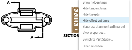
Show/hide offset cut lines
From an section view, you can toggle the visibility of offset cut lines by right-clicking on the section view and selecting Show/hide > Show offset cut lines or Hide offset cut lines from the context menu:
Show/hide sketches for Part Studios
Showing sketches comes in handy show flat pattern sketches on drawing views of those flat patterns for sheet metal.
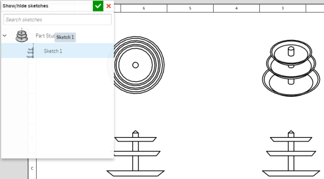
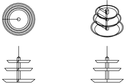
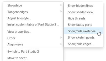
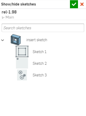
For views of parts, this command shows or hides selected sketches from within a Part Studio. Select the view, then right-click and select Show/hide > Show/hide sketches. When the Show/hide sketches dialog opens, select the sketch from the menu. You can select more than one sketch. This dialog displays all sketches in the Part Studio in which the part was modeled. Selecting the same drawing sketch for each view displays the sketch in each view's perspective.
To hide a sketch, open the Show/hide sketches dialog again and click to un-select the sketch or sketches.
Insert sketch
To insert a sketch on a section view:
- Right-click on the section view and select Show/hide > Show/hide sketches (first image below) to open the Show/hide sketches dialog (second image below):
-
From here, click on the sketch or sketches you want to insert.
-
Click the
 checkmark in the top right corner of the dialog box to insert the sketch or sketches into your section view.
To remove a sketch on a section view:
-
Right-click on the section view and select Show/hide > Show/hide sketches from the context menu.
- Click on the sketch or sketches you want to remove (notice they are no longer highlighted in blue).
-
Click the
checkmark in the top right corner of the dialog box to finish removing the sketch or sketches.
Show/hide sketches for Assemblies
For views of assemblies, this command toggles the visibility of selected sketches from the Assembly (sketches must first be inserted into an Assembly). By default, assembly sketches are hidden.
To toggle sketch visibility, right-click on the view and select Show/hide > Show sketches or Hide sketches from the context menu.
When shown, all sketches inserted into the Assembly become visible in the drawing.
Show/hide sketch points
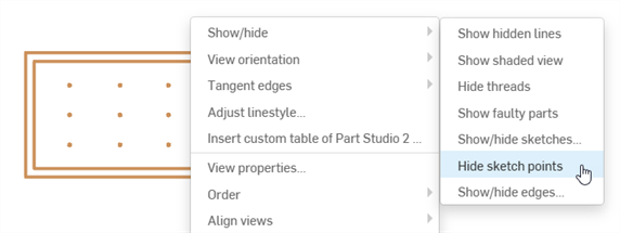
If a sketch with sketch points is inserted into the Drawing, the sketch points are visible by default.
To toggle their visibility, right-click on the view, and select Show/hide > Show sketch points or Hide sketch points from the context menu:
To customize the appearance and size of the sketch points in the drawing, use the Drawing properties panel, Construction geometry tab.
Show/hide edges
Show or hide the edges of a drawing. This functionality is available from all drawing views.
Select the view, right-click and then select Show/hide > Show/hide edges from the context menu (first image below). The Show/hide edges dialog opens (second image below):
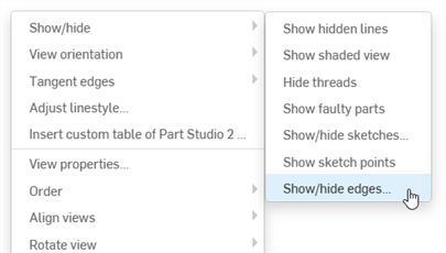
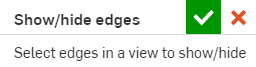
Select any edges from your view that you would like hidden. The edges turn thicker and are colored gray to indicate they are marked as hidden. Hidden lines are also displayed in gray to help you define which edges to show. If you make a mistake, click the edge once again and it turns black (indicating it will remain displayed). Click the green checkmark in the dialog. Any edges marked as hidden are hidden from view.
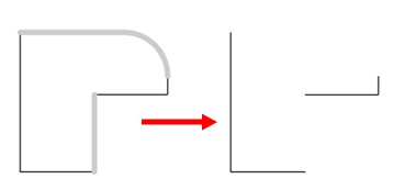
To show any hidden edges, reverse this process. Select the view, right-click and select Show/hide > Show/hide edges from the context menu, select any hidden (grey) edges that you would like displayed. Then click the green checkmark in the dialog.
Show/hide centerlines
Shows or hides automatic centerlines that are added to circular geometry (holes, cylinders, and spheres) from view. Any centerlines added using the centerline drawing tools are not hidden.
Select the view, right-click and then select Show/hide > Hide centerlines (or Show centerlines) from the context menu:
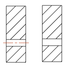
Automatic centerlines shown at left (default), and hidden at right.
Show/hide auto centermarks
When a view with a part that has a Hole feature is inserted into a drawing, its centermarks are automatically displayed if the view is normal to the face where the hole is inserted. Similarly, if a Hole feature is patterned (circular or linear) or mirrored, automatic centermarks are displayed. For circular or linearly patterned holes, connecting lines between centermarks are also displayed.
To toggle the visibility of automatic centermarks, right-click on the view and select Show/hide > Show auto centermarks or Hide auto centermarks from the context menu:
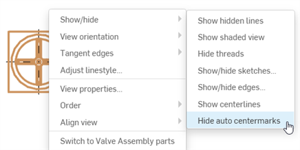
For more information on centermarks, see Centermark.
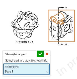
Show/hide parts
By default, parts are always visible when a view is inserted into a drawing.
To toggle their visibility, right-click on the view and select Show/hide > Show/hide parts from the context menu.
A dialog opens. With focus in the Hidden parts field, select the parts in the view that you want to hide. Click the checkmark () to accept and close the dialog.
For example:
Show/hide constraints
By default, sketch constraints are hidden in the view.
To toggle their visibility, right-click on the view and select Show/hide > Show constraints or Hide constraints from the context menu:
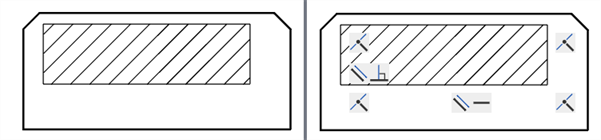
Constraints hidden (left), and shown (right).
Show/hide center of mass
The center of mass indicator ( ) can be added to drawings of parts and composite parts with assigned materials. Dimensions can be attached to the indicator.
To toggle the center of mass indicator visibility, right-click on the view and select Show/hide > Show center of mass or Hide center of mass from the context menu:
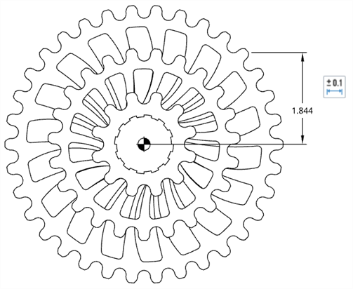
Dimension attached to a part's center of mass indicator.
Adjust the indicator's size in the Drawing properties panel.
View orientation
Change the orientation of a selected view. Right-click on the view and select View orientation from the context menu. The current view orientation will be grayed out in the menu:
- Top
- Left
- Right
- Front
- Back
- Bottom
- Isometric
These commands are also available through the View properties dialog as well.
Tangent edges
Tangent edges are edges formed between a curve and linear edge; for example, from fillets or smooth edges.
To select the visual treatment of tangent lines, select the view, right-click and select Tangent edges and then select from the following three modes:
- Hidden - Tangent edges are visually removed from the drawing.
- Solid - Tangent edges are shown by solid lines. This is the default.
- Phantom - Tangent edges are shown by broken lines.
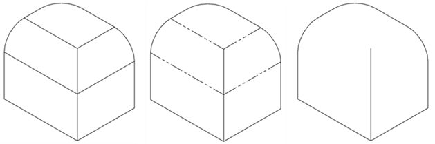
Three different tangent edge options, from left to right: Solid (default), Phantom, and Hidden.
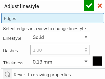
Adjust line style
-
Right-click on the view to open the context menu and select the Adjust linestyle command.
-
Click on each edge in the view to apply the specified style changes; these selections appear in the dialog under Edges.
-
In the dialog, adjust the following to your specifications:
-
Linestyle - Select a line style from the drop down.
-
Dashes (if dashed line) - Customize the spacing of line dashes.
-
Thickness (in specified units)
-
Color - Click the color block and adjust accordingly in the color dialog.
-
-
Close the dialog with
.
Insert custom table
To insert a custom table, see Custom table.
View formatting options
The next section in the context menu relates to view formatting:
View properties
See View properties.
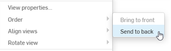
Order
Sets the order of the current view in the drawing layer stack.
-
Bring to front - Brings the current view to the front of the drawing layer stack.
-
Send to back - Sends the current view to the back of the drawing layer stack.
Align views
Align two selected views vertically or horizontally, according to their view centers.
-
Right-click on a view, or select a view and then right-click to activate the context menu.
-
Hover over the Align views option, then select Vertically or Horizontally.
The cursor changes to a selection cursor.
-
Select another view to align the view with.
The views are aligned and the selection mode is exited.
Rotate views
For rotated views, you can elect to rotate them vertically or horizontally, according to a selected straight edge. The commands are found in the view context menu:
- Select a view.
- Right-click to activate the context menu.
- Select
Rotate view vertically
or
Rotate view horizontally.
The cursor changes to a selection cursor.
- Select a straight edge with which to rotate the view.
The view is rotated and the command mode is exited.
View navigation options
Following are various ways to copy and paste data from and into views:
-
Switch to. . . - Switches to the tab from which the view was inserted. This can be a Part Studio or Assembly.
-
Move to sheet - See Moving a view to another sheet.
-
Copy - Copies the current view to the clipboard. See Copying a view.
-
Paste - Pastes the current view from the clipboard into the current sheet.
-
Paste as table - Copy table cells from a Microsoft Excel worksheet or Google Sheet, and paste them into an Onshape drawing as a new table. See Copying a table from Excel or Google Sheets.
-
Group/Remove view from group - Group combines a hatch to a view, for example. Once grouped, the views are moved together. Select Remove view from group to remove the currently-selected view from the group.
Select for replication/Replicate annotations
Copy a view or region's annotations to be replicated on another similar view with like geometry. Views do not need to be linked.
-
Select a view.
-
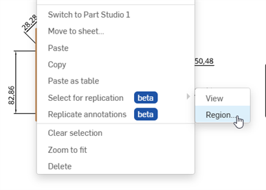
Right-click and select one of the following options:
-
Select for replication > View - Copies all view annotations to the clipboard.
-
Select for replication > Region - The Replicate region dialog opens.
-
Adjust the size of the selection box using the corner point handles.
-
Place a rectangular center point selection on the view.
-
Press Enter or click the checkmark (
). The annotations from the region are copied to the clipboard.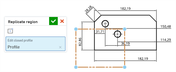
-
-
-
Select the view in which you want the annotations replicated.
-
Right-click and select Replicate annotations.
-
If a View was copied, its annotations are pasted into this view.
-
If a Region was copied, a solid-edged box is displayed with the cursor at its center.
-
Click to place a selection box on the view.
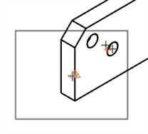
-
Adjust the size of the box using the corner point handles.
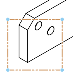
-
Press Enter or click the checkmark (
). The annotations are pasted into this view.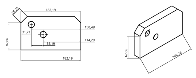
-
-
The number of successfully replicated annotations are provided in a notification at the top of the graphics area:

Additional options
-
Edit [view] - Select the broken-out section, crop, detail, or auxiliary view, right-click and select Edit [view], For section, detail, and crop views, use the dialog that opens to edit the rectangle/circle/spline/polygon. Add spline points, drag the shape into a new size or location, or change other specifications. For auxiliary views, use the dialog to provide a label, alter the originating view edge, flip the view, or turn on/off view plane visibility.
-
Display state - Select a view, then right-click and hover over Display state to display a list of available display states for the view. Select one. For all parent views, the default is 'show all.' All child views default to 'follow parent' display state. Section and Detail views will only ever 'follow parent' display state.
If you create a display state after creating the drawing, update the drawing to make use of the display state. If you delete a display state from the assembly, then upon drawing update a Failed to resolve exploded view error message is displayed.
Any views using the deleted display state will be empty, but remain on the drawing. The name of the deleted display state no longer appears in the context menu.
-
Explode/Position - Select a view, then right-click and hover over Explode/Position to display a list of available explode or position states that can be selected for the view. If you create an explode view after creating the drawing, update the drawing to make use of the explode. If you delete an explode view from the assembly, then upon drawing update a Failed to resolve exploded view error message is displayed.
Moving the rollback bar in the Exploded tree between explode steps does not affect the drawing view. The drawing views reflect all explode steps in an Exploded view.
-
Suppress alignment with parent - Select a child view, right-click and select Suppress alignment with parent to disconnect the automatic alignment of views derived from other views in order to place them independently on the drawing.
When suppressing an alignment, you are not breaking the alignment to the view’s children. If the view has children (or any alignments) you will not be able to rotate the view.
-
Remove section/remove crop - Select a section or crop view, right-click and select Remove section (or Remove crop) to remove the broken-out section or crop view and leave the spline/circle/polygon for reference. To remove the boundary, click to highlight it, then either press Delete, or right-click and select Delete.
-
Edit Hatch section/Edit Hatch region - Add or edit a hatch region in a view. If a hatch region is already added, this opens the Edit hatch dialog. Click the hatch area of the drawing, and a set of options opens in the dialog, where you can adjust the hatch type (ANSI, ISO, or General), pattern, scale, angle, and color.
-
Grouping notes with a view - See Grouping notes
-
Clear selection - Deselects the current view.
-
Zoom to fit - Fits the current view in the window frame
-
Delete - Deletes the current view