Drawing Properties - Annotations
![]()
Available in: Drawing
Edit the current drawing's font, text height, arrowhead length and type, and color of each annotation type in your drawing. Supply defaults for all annotations at once, or Notes, Callouts, Datums, Geometric tolerances, Surface finish symbols, Weld symbols, Hole callouts, and Bend notes (for sheet metal) separately.
To access Annotation properties, click the Annotations icon (![]() ) at the top of the Drawing properties toolbar.
) at the top of the Drawing properties toolbar.
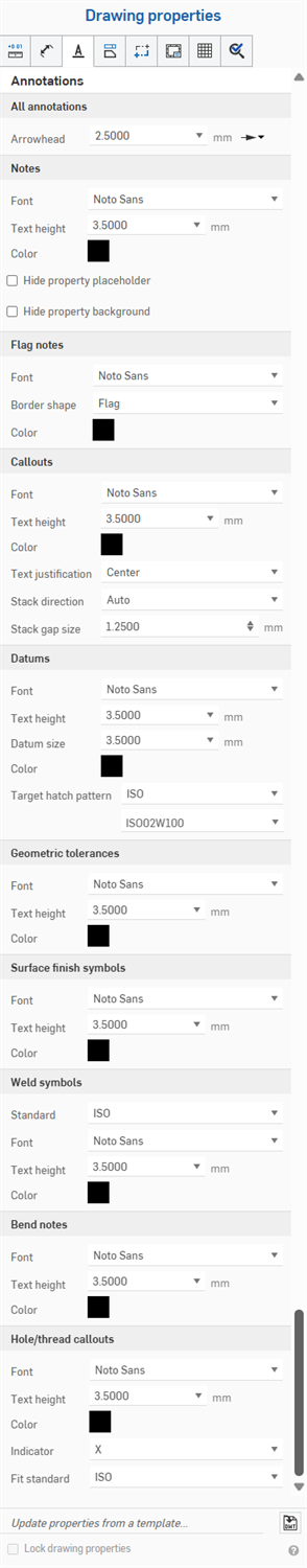
Properties that are common to all annotations are explained below. Any properties specific to an annotation type are explained under that subheading, following this section.
- Font - Select the font of choice for each annotation type.
- Text height - Select the size of choice for each annotation type.
-
Color - To edit colors for any annotation entity, click the corresponding color block to access the color dialog:
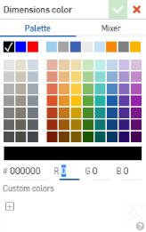
- Select Palette to choose a color or enter a hex or RGB codes. Use the Mixer panel to drag to a general color area and then enter a specific hex or RGB code.
On either the Palette or Mixer panels you can click the plus sign under Custom colors to save the currently specified color value as a custom color for later use.
- Arrowhead - Select the arrowhead size.
Specify the defaults for all note properties, including Font, Text height, and Color.
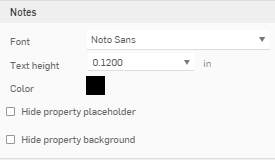
You can also specify to:
-
Hide property placeholder (----, as in the title box)
-
Hide property background (gray by default, as seen in the title box)
Note that all exported drawings will, by default, no longer contain Drawing and Sheet Property placeholders ("----").
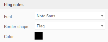
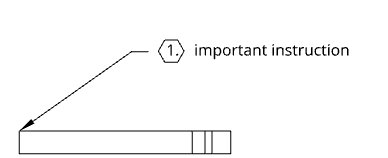
Specify the defaults for all flag notes, including Font, Border shape, and Color.
Specify the defaults for all callouts, placed in space or attached to geometry, including Font, Text height, Color, Text justification, Stack direction, and Stack gap size.
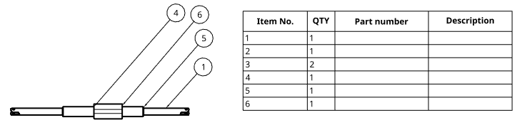
The callouts in the drawing correspond to the Item No. column in the BOM
Specify the defaults for all datum properties, including Font, Text height, Datum size (the size of the triangle), and Color.
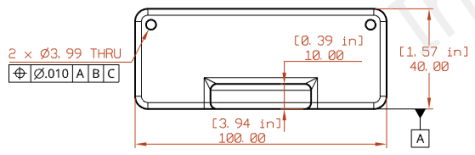
Specify the defaults for all geometric tolerances, including Font, Text height, and Color.
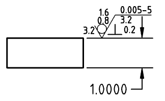
Specify the defaults for all surface finish symbols, including Font, Text height, and Color.
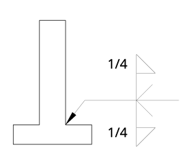
Change the standard for the Weld symbol at the bottom of the Annotations menu. This menu changes the default standard for the Weld symbols used in the drawing. This standard is separate from the standard of the drawing and does not change that. For example, for an ANSI standard drawing you could change this setting and use all ISO Weld symbols in your drawing.
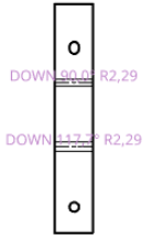
Change the formatting for bend notes attached to sheet metal views, including font, text height and color. Bend notes come into the drawing from the bend specifications made in the Part Studio:
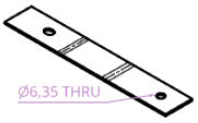
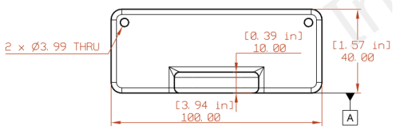
Change the formatting for hole callouts attached to sheet metal views, including font, text height, color, and indicator. Hole callouts are applied to a drawing of a sheet metal flat pattern through the Dimensions dropdown menu, Hole callout tool
![]() .
.