![]()
Place a surface finish symbol on the edge of a circular view, the face of a part, or away from edges.
步驟
- Click
 .
. - 在對話方塊中使用這些欄位來描述表面加工符號。
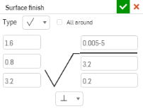

- Click in the drawing to place the symbol and surface finish descriptions:
- 在工程圖空白圖紙的任意處按一下
- 按一下環狀是塗邊線上的一個點
- Click a view region on the face of a part
- 如果需要,可在對話方塊中輸入更多的說明描述與放置更多的符號。
- Click
 when finished (or
  to cancel).
若要加入另一條導線,在符號上按右鍵,然後選擇 [加入導線 ]。按一下來放置導線,重複這些步驟來加入多條導線。
導線包括一個可沿水平線段移動的節點:
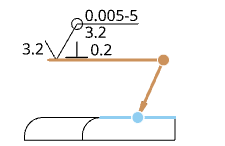
按一下並拖曳節點來延伸或縮短導線的水平線段。
您可以將表面加工符號與尺寸界線相關聯:
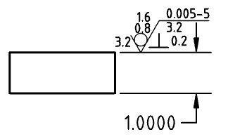
在導線上按右鍵,然後按一下 [新增節點]:
- 在導線上按右鍵,然後按一下 [新增節點]:
![在環境選單中強調顯示 [新增節點] 指令的螢幕擷取畫面](Resources/Images/drawings-tools/add-node-contextmenu-surfacefinish.png)
若要從導線中移除節點,請在節點上按右鍵,然後選擇 [移除節點]。
- 若要從導線中移除節點,請在節點上按右鍵,然後選擇 [移除節點]。
- 修改文字
設定表面加工符號的樣式
設定表面加工符號樣式:
-
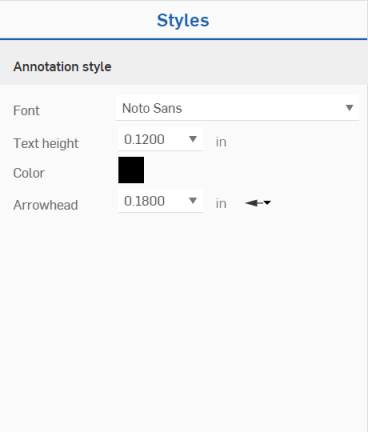
Click on the surface finish symbol you want to style, then click the Styles panel icon on the right side of the page:
-
編輯符號的「字型」、「文字高度」、「色彩」與「箭頭」:
表面加工符號環境選單
在表面加工符號上按右鍵來開啟環境選單:
- Edit - Open the surface finish dialog to edit the surface finish specifications.
- Copy - Copy the surface finish symbol.
- Add leader - Add a leader (or another leader) to the surface finish symbol.
- Remove leaders - Remove all leaders from the surface finish symbol.
- Move to - Move a surface finish symbol to a different layer of the drawing: Border frame, Border zones, or Title block. Once on another zone, you have the option of locking the layers (through Drawings properties, Formats tab), in order to stabilize the position of entities on that layer. When a surface finish symbol is moved to different layer, that layer's formats (for example, color, line thickness, and font) are applied to it.
- Clear selection - Remove any highlighted items from the selection queue.
- Zoom to fit - Zoom appropriately to fit the entire drawing in the field of view.
- Delete - Delete selected entities.
提示
- You can group surface finishes with callouts. See Callout (Balloon) for more information.