結合
![]()
![]()
![]()
在 Onshape 中的結合與在舊式 CAD 系統中的結合有所不同。在兩個實例間的移動 (自由度) 是內嵌於結合的情況下,許多組合件在任兩個實例間僅需要一個 Onshape 結合。結合包含了自己的座標系統,所以您可以使用一個結合來定義兩個圖元之間的自由度。在兩個圖元間放置結合時,Onshape 會在每個圖元上提供點來與結合的座標系統對齊。建議的位置是根據零件的基礎幾何來決定的,變更幾何將會變更結合的位置。在某些案例中這些情形可能是您不想要看到的,但您也可以:
- 在建立結合時,如果幾何並未允許一個隱含的結合連接器,則請在您所需圖元處加入一個明確的結合連接器。詳細資訊請參考結合連接器。
- 在組合件中插入一個配置或參考草圖以用於對齊結合連結器。
- 在需要時使用多於一個結合。
快速鍵:m
使用快速鍵 j 來在組合件中隱藏/顯示結合。
您可以在組合件中將圖元與原點結合。您也可以使用環境選單或拖曳來固定一個圖元以測試所指定結合的移動情況。
圖元包括:零件、組合件、次組合件、草圖與曲面。
在 Onshape 中的結合有兩個面向:結合連接器和結合。Onshape 並不直接將實體幾何結合在一起,而是使用結合連接器。結合連接器是在圖元上或其間的局部座標系統圖元,用於結合特徵中以在實例之間相互定位與定向。結合連接器是在結合對話方塊之外明確地建立,或是在建立結合的過程中隱含產生的。
開始一個新的結合特徵。可以從對話方塊中輕鬆地編輯結合類型,可快速地變更結合。Onshape 會根據實例的預期行為定義結合。每個結合各會限制某些自由度,「緊固」則會限制所有六個自由度。
在有啟用的結合特徵時,將游標移動到面與邊線上暫留以顯示隱含的結合連接器,這代表可以放置結合連接器的潛在位置。這些點會出現在面或草圖輪廓的質心、中點、頂點、圓形開口的中心、切除的負空間中心,以及圓錐面的虛擬交角。
按住 Shift 鍵來在移動游標時鎖住目前的參考面或邊線。這會使得選擇位在狹小區域或負空間中的點更為容易。在將游標移動到幾何上時,結合連接器會抓取到最近的點上。
在這個範例中,第一個選取的項目是在鑽孔中心的結合連接器點。這個面應與另一個實例上的圓形面接觸並對齊。圓形面與邊線是選擇結合連接器最快速的方式,因為它們沒有中點或頂點,而是只有質心。這個結合的第二個選取項目是在第二個實例上的環狀邊線,應與此處與第一個實例接觸並對齊。這些實例會一起移動,並以對齊的結合連接器主 Z 軸來定位。
按一下箭頭圖示來反轉主軸的方向。按一下「重新定向副軸」圖示來以 90 度的增量旋轉副軸。欄位上方的結合連接器代表反轉或旋轉的實例。如果其動作受到限制,則會改由欄位下方的結合連接器來反轉或旋轉。若要重新定向另一個結合連接器,按一下「重新排序項目」然後使用右側的控制柄重新排列。按一下 [完成] 來確認重新排序。現在當重新定向副軸時,另一個結合連接器會旋轉。
每個結合特徵會定義結合連接器之間的自由度。使用「製作結合自由度動畫」圖示來視覺查看結合的移動。「緊固結合」有零自由度,所以結合連接器之間沒有任何移動。如果將結合類型變更為「滑動」,所產生的動畫則會是沿著主要的 Z 軸移動實例。
結合特徵支援偏移與套用限制。使用「偏移」來以設定的值沿軸移動或旋轉實例。使用「限制」來限制結合的動作範圍。可用的限制是取決於結合的自由度。
在定義結合特徵時,Onshape 並不會持續計算所有的結合與其位置,而是等到接受了結合特徵之後才計算。使用 [解出] 來計算所有的結合特徵並更新實例的位置。
在結合特徵之下,會依時間順序列出定義的結合。有限制的結合會顯示一個限制的圖示。將游標移動至一結合上暫留來查看結合的偏移與限制的定義。在結合上按右鍵以使用其環境選單。用環境選單或連按兩下結合來編輯結合。「套用限制位置」來觀察根據所定義限制的完整動作範圍。「重設」來將結合恢復到其原始的位置。「刪除」會將結合從組合件中移除。
結合是在結合對話方塊中定義的:
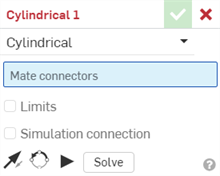
先選擇您要建立的結合類型,然後選擇結合連接器 (一個零件上選擇一個)。您也可以核取方塊來套用移動的限制。其他的選項/動作包括:
-
 - 反轉主軸,即實例的 Z 方位。
 -
 - 重新定向副軸;點按即可以 90 度旋轉實例的象限方位 (在 XY 平面上)。
 -
 - 預覽結合無限制動作的動畫,忽略組合件中所有其他的結合。
 - 解出 - 解出組合件中包括這結合的所有結合。
許多結合提供設定偏移距離的功能,以定義要結合零件間的固定空間,以及移動中距離的限制。
會在圖形區域以虛線與終端短列視覺顯示限制。虛線代表移動的方向與距離,實線則代表限制。
如果結合上套用有一或多個限制,則在「結合特徵」清單中的結合右側會有結合限制指標圖示 ![]() 。
。
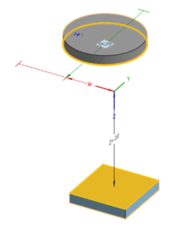
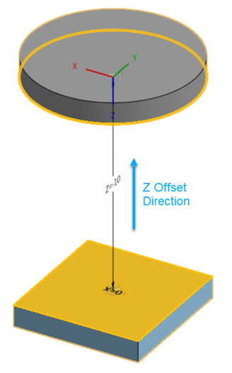
在圖形區域的結合之間會以虛線視覺顯示偏移的距離,同時顯示值與軸。請在對話方塊中輸入距離。
當您點按一個結合時,會顯示表明 X、Y 與 Z 方向的圖形,這是由結合與偏移,在加上限制尺寸的範圍 (如果有的話) 所定義的。
應將套用偏移視為移動整個座標系統。偏移是相對於第一個所選的結合連接器的。
當核取了「偏移」方塊時,許多結合會提供一個可指定特定軸旋轉的選項:滑動、轉動、銷槽與平面這些結合會提供這個選項,請見下圖:
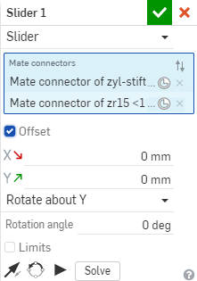
上圖中選擇了要繞著旋轉的軸,然後要再輸入旋轉的角度
當您開啟「結合」對話方塊並選擇兩個結合連接器時,會在您的游標上出現抬頭顯示:

按一下在抬頭顯示中的核取記號來提交目前的結合並開始一個新的結合。結合對話方塊會保持開啟,您可以隨意繼續選擇結合。
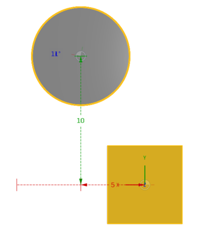
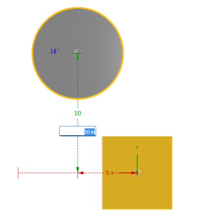
在圖形區域中會在結合之間以虛線視覺顯示偏移的距離,距離值是可編輯的。拖曳零件至所需的位置,連按兩下距離值,然後輸入一個新值。這些值不是固定不變的;您可以參考這些值來在對話方塊的 [偏移] 欄位中輸入估計的值,或將零件放置在精準的位置來取得測量值。例如:
軸與旋轉移動的結合值 (上方)。
編輯中的結合值 (上方)。
使用結合的環境選單來存取下列的指令:
- 重新命名 - 為結合指定一個不同的名稱
- 編輯... - 變更結合的定義 (即使結合是抑制的)
- 套用限制位置 - 當為結合建立一個限制時,自動將實例移動到最小或最大的限制值。
- 重設 - 在拖曳組合件測試結合的移動之後,使用重設來將組合件返回至其起使/原始位置 (假定並沒有限制條件拘束此操作)
- 製作動畫 - 以單一結合 (或結合內的單一自由度) 驅動組合件
- 隱藏 - 從視圖中移除 (「顯示」會再次顯示結合)
- 顯示所有結合 - 顯示所有結合連接器
- 隔離顯示 - 暗化與停用除所選項目 (或與所選結合相關的項目) 之外的所有其他零件。在隔離顯示模式中時,「退出隔離顯示」出現在功能表的最上方。詳細資訊請參考管理組合件。
- 設為透明 - 將最靠近所選結合的零件變暗。使用「設為透明」對話方塊中的滑桿來根據與所選結合的距離或相連性將透明度延伸至其他零件中。
- 抑制 - 視覺顯示沒有結合的組合件 (而不刪除結合);當與結合或結合連接器關聯的零件或組合件受抑制時,會自動將結合或結合連接器設定為非啟用的 (仍可編輯抑制的結合)。
- 清除選取項目 - 清除所有的選擇
- 刪除 - 從組合件中移除結合
在於兩個明確或隱含的結合連接器之間建立結合之後,您可以編輯任何一個結合連接器:
-
開啟結合對話方塊。在下方的範例中使用「緊固」結合來說明。除了未使用結合連接器的「相切」結合外,這個過程對所有的結合都是類似的。
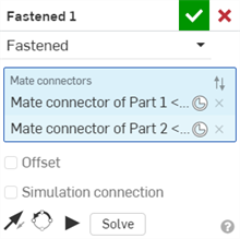
-
按一下「結合連接器」圖示 (
 )。「結合連接器」對話方塊開啟,您可於其中編輯結合連接器的起源類型、起源圖元、對齊、位置、主軸方向、與副軸方位:
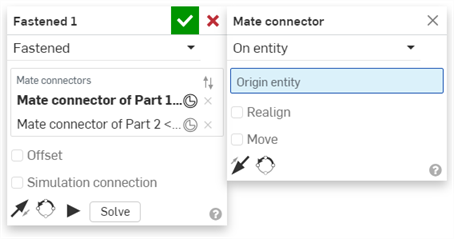
在結合對話方塊中編輯結合連接器是僅限於位在目前組合件中隱含或明確的結合連接器。對於來自 Part Studio、次組合件、或連結文件中的結合連接器,則必須在其原始的位置編輯。
詳細資訊請參考結合連接器。
在建立結合,且結合列於「結合特徵」清單之後,請選擇一個結合 (或 Ctrl+按一下來選擇多個結合),然後拖曳/置放結合以在清單中重新排序。這樣有助於將最重要的結合特徵放在清單中較高與較顯眼的位置。Onshape 會同時解出結合,因此排列的順序不會影響結合。
除了「球面」、「緊固」、「相切」與「寬度」結合之外,您可以指定所有結合的結合值,Onshape 會提供從第二個所選結合連接器到第一個連接器的距離視覺提示,提供使用預設單位的距離值。您可以用正值或負值來指定限制。
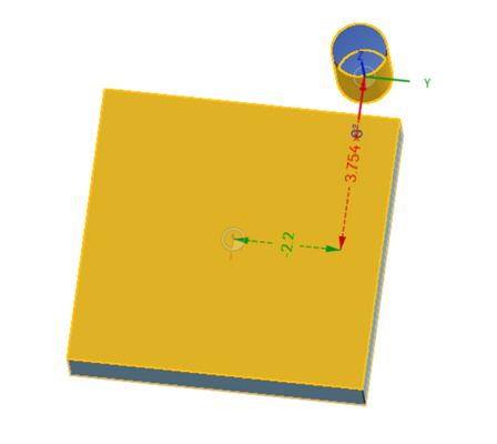
在此範例中,在方盒中的結合連接器是在對話方塊中第一個被選擇的;在圓柱上的結合連接器是第二個選擇的。請注意,Y 值是負的,X 值是正的。
現在將選擇結合連接器的順序調換,請注意距離值的變化:
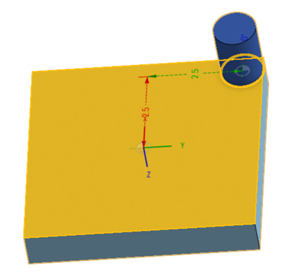
請注意在這個案例中,Y 的值是正的且 X 值也是正的。這是由於從一個結合連接器到另一個結合連接器測量順序的關係。請記住,測量是沿著座標系統從第二個所選結合連接器到第一個連接器而來。
使用這些距離視覺化工具來估計在限制方塊中輸入的值:
- 當結合中有限制核取方塊出現時,按一下來啟用自由度欄位以輸入最小與最大距離的值,距離的測量是從所選的第二個結合連接器到所選的第一個結合連接器。
- 使用距離視覺化工具做為導引 (拖曳零件來啟用),輸入最小與最大值。
- 使用播放的按鈕來製作包括限制的移動動畫。
您可以在組合件的數值欄位中使用表達式與三角函數。
Onshape 會提供視覺指標,以決定那些實例具有不受約束的自由度或動作。
如果實例可在其自由度間移動,會在清單中的實例旁看到一個三向圖示。移動游標至此圖示上暫留以顯示有自由度的工具提示。使用清單中的鎖住圖示來切換次組合件的剛性固定,或在次組合件上按右鍵,然後選擇 [鎖住/追隨位置至]。在鎖住至目前位置或追隨位置至命名位置間選擇。
如果次組合件中的所有零組件都是完全約束的,則會顯示剛性圖示,而不是標準組合件的圖示。
最上層組合件的圖示表示組合件在空間中的約束方式:可以是固定的,也就是將實例鎖在其目前的位置,或是用結合將其與原點緊固。當將組合件插入至另一個組合件時,這兩個限制都不會延續至其中。只應將一個基礎零組件以這種方式定義。
有好幾個觀察組合件動作的方法。最簡單的方法是就點按並拖曳組合件可移動的實例。移動是取決於已定義的結合特徵。例如,滑動結合會限制這個活塞次組合件與管子間的自由度,而僅允許一個線性自由度。這個結合已建立了一個限制,意味著它只能拖行一段距離就會停止。
三向操控器提供了精準的拖曳,允許用指定的值定義移動。
有自由度的結合可以選擇製作動畫。在清單中的結合上按右鍵,然後選擇 [製作動畫]。會提示要為有多個自由度的結合做出選擇。如果已有限制套用到結合上,會自動將「開始值」與「結束值」設定為該限制預設的整個範圍。輸入值來指定動作範圍。「步驟」定義動畫的速度。較低的值會製作出較快的動畫,較高的值則會產生較慢的動畫。在「播放類型」之下,選擇「單次」來播放動畫一次,「往復」會從起始值播放到結束值然後再返回,直到手動停止為止,「循環」從頭到尾持續播放,直到手動停止。按一下箭頭圖示來反轉動畫。 「目前值」是唯讀的欄位,隨著動畫過程中結合的移動來填入。
按一下「播放」圖示來檢視動畫,按一下「停止」圖示來停住。
使用動畫指令 (在結合與結合指標的環境選單中) 來以單一結合 (或結合內的單一自由度) 驅動組合件。同時會強制執行與實行組合件中的其他結合與條件關係。
如果定義了結合的限制,會在動畫的過程中使用這些值來做為起始點與停止點。
- 在結合或結合指標上按滑鼠右鍵,然後選擇 [製作動畫]。
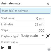
- 動畫一次僅能與一個自由度一起使用,如果結合有多個自由度,系統會提示您選擇一個。
- 輸入「開始值」與「結束值」。如果在結合定義中指定了限制,則會自動將那些值移入至「開始值」與「結束值」欄位中。如果在結合對話方塊中沒有指定限制,請現在輸入值。
- 開始值 - 沿著自由度軸量測的最小距離 (根據預設,此值是在結合最小限制中指定的值)。
- 結束值 - 沿著自由度軸量測的最大距離 (根據預設,此值是在結合最大限制中指定的值)。
您可以於此處輸入最多 36000 度 (100 次旋轉),這對在高比例齒輪與齒條和小齒輪關係中視覺查看自由度是相當有用的。
- 指定步驟,這是從開始到結束值的線性對應,在每個步驟包含內插。最少的步驟數是 2。根據預設, 播放是大約 60 步驟/每秒。
- 選擇一個播放的類型,分別可以是單次播放自由度的動畫或是往復播放直至手動停止為止。
「目前值」是唯讀的欄位,是根據動畫過程中結合經自由度移動時產生的值移入而來,會以您指定的單位顯示。當動作停止時 (自動或手動停止),「目前值」會顯示動作被停止的點。
動畫支援所有的結合類型,但不建議用於「緊固」、「相切」、或「球面」結合是驅動結合的情況中。
提示
- 「製作動畫」的指令可在不同的圖形模式中使用,像是隔離顯示、結合指標與結合連接器。
- 動畫可幫助您探索結合之間的關係與限制條件的環境,並提供一個展示設計的方式 (特別是針對旋轉自由度的循環播放功能)。
為下列的結合類型提供於組合件操作過程中將一個圖元從另一個圖元偏移:
- 平面偏移 - 沿 Z 軸
- 滑動偏移 - 沿 X 與 Y 軸
- 旋轉偏移 - 沿著 Z 軸
- 銷槽偏移 - 沿 Z 軸
- 緊固偏移 - 沿 X、Y、和 Z 軸
您也可以拖曳圖元然後在圖形區域中觀察距離值。這樣可以幫助決定在對話方塊中要輸入的指定值。
您可以在組合件的數值欄位中使用表達式與三角函數。
您可以複製與貼上已在組合件中結合的圖元:
- 選擇圖元。
- 從環境選單中選擇 [複製] 項目:
- 從環境選單中選擇貼上項目:
會直接將圖元貼至滑鼠點按處。
請注意,在「組合件」清單中的圖元、結合連接器與結合同時也被複製。
除了在組合件清單中出現外,結合在圖形區域中也有指標。您可以在「組合件」清單中隱藏圖元與結合連接器來更清楚地看到結合指標。這些指標提示了結合定義的動作類型以及目前的狀態:藍色/白色表示良好的結合,灰色表示是抑制或非啟用的,紅色則是有問題 (仍可編輯抑制的結合)。


 緊固
緊固


 轉動
轉動


 滑動
滑動


 平面
平面


 圓柱
圓柱


 銷槽,在槽的方向上有箭頭


 球面
球面
![]()
![]()
![]() 平行
平行


 相切
相切
![]()
![]()
![]() 寬度
寬度


 群組
群組
更多視覺查看結合的提示:
- 選擇一個零件,於其上按右鍵來存取環境選單,然後選擇顯示結合。
- 將游標移動暫留至結合上,按右鍵存取環境選單來從中選擇在結合上的動作。
- 在圖形區域中選擇結合、結合連接器、或結合條件,相關聯的實例與結合特徵會在清單中被強調顯示。
- 兩個實例間僅有一個結合。
- 固定一個圖元與套用結合有所不同。「固定」 (在環境選單中) 是針對套用固定於其中的組合件的;並不會繼續存在於圖元被插入至的另一個組合件中。
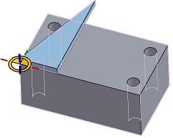
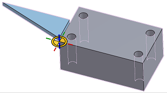
- 結合會將兩個實例以某種關係相互定位,使每個實例上的結合連接器對齊。
結合之前
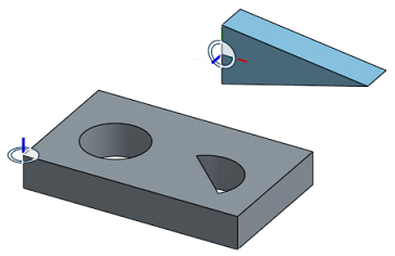
結合之後
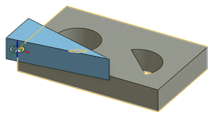
- 最初的位置通常是最佳的猜測。有兩個工具可更正位置:
- 反轉主軸工具會反轉主軸 (Z) 的方位。


- [重新定向副軸] 工具以 90 度的增量調整方位
- 播放按鈕
 產生建立的結合間所允許移動的動畫。
 - 「解出」按鈕會重生成處理中的結合以及所有結合的移動,所以您可以查看變更如何影響整個組合件。
結合類型則會指定自由度的行為。
- 選擇一個結合 (例如
 ) 來開啟對話方塊:
- 在每個圖元上選擇一個自動的結合連接器 (您也可以與原點結合):
- 如果需要,使用反轉主軸或旋轉副軸來調整方位。
- 接受結合
 。
。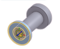
在上面的範例中,僅使用自動的結合連接器。在大部分的結合案例中,使用自動結合連接器是沒有問題的。在較少數的案例中,之前先建立結合連接器是相當有用的。您可以在組合件或 Part Studio 中建立結合連接器。
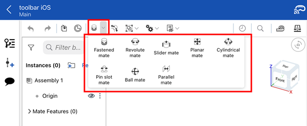
在 Onshape 中的結合與在傳統 CAD 系統中的結合有所不同。在兩個實例間的移動 (自由度) 是內嵌於結合的情況下,您在任兩個實例間可能只需要有一個 Onshape 結合。
您可以將圖元與組合件的原點結合。您也可以使用環境選單來固定一個圖元以測試所指定結合的移動情況。圖元包括:零件、組合件、次組合件、草圖與曲面。
結合是在結合對話方塊中定義的:
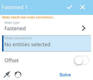
選擇要建立的結合類型,然後選擇結合連接器 (一個零件上選擇一個)。
結合類型 - 結合類型欄位顯示您要使用的結合類型。輕觸來開啟結合類型的清單,然後輕觸來選擇一個項目。
結合連接器 - 接下來的結合連接器的區域是以藍色強調顯示。這表示需要有來自圖形區域的選取項目。必須選擇兩個結合連接器 (一個結合的實例上要有一個)。
偏移 - 輕觸來設定偏移距離以定義要結合零件間的固定空間。
限制 - 輕觸來設定移動的距離限制。
![]() - 反轉主軸,即實例的 Z 方位。
- 反轉主軸,即實例的 Z 方位。
![]() - 重新定向副軸;輕觸即可以 90 度旋轉實例的象限方位 (在 XY 平面上)。
- 重新定向副軸;輕觸即可以 90 度旋轉實例的象限方位 (在 XY 平面上)。
解出 - 輕觸以解出包括目前這個結合的所有組合件結合。
除了球面、緊固與相切結合之外,您可以指定所有結合的移動限制。
在允許限制的結合 (轉動、滑動、平面、圓柱與銷槽) 對話方塊內,開啟 [限制] 的按鈕,限制的欄位隨即出現。
輸入所要的限制條件,然後輕觸解出來視覺檢視變更。
為下列的結合類型提供於組合件操作過程中將一個圖元從另一個圖元偏移:
- 平面偏移 - 沿 Z 軸
- 滑動偏移 - 沿 X 與 Y 軸
- 旋轉偏移 - 沿著 Z 軸
- 銷槽偏移 - 沿 Z 軸
- 緊固偏移 - 沿 X、Y、和 Z 軸
您也可以拖曳圖元然後在圖形區域中觀察距離值。這樣可以幫助決定在對話方塊中要輸入的指定值。
您可以在 Assembly 的數值欄位中使用表達式與三角函數。
除了在組合件清單中出現外,結合在圖形區域中也有指標。您可以在組合件清單中隱藏圖元與結合連接器來更清楚地看到結合指標。這些指標提示了結合定義的動作類型以及目前的狀態:藍色/白色表示良好的結合,灰色表示是抑制或非啟用的,紅色則是有問題。請注意,在與結合或結合連接器關聯的零件或組合件是受抑制的情況下,結合或結合連接器也是受抑制的 (仍可編輯抑制的結合)。
![]()
![]()
![]() 緊固
緊固
![]()
![]()
![]() 轉動
轉動
![]()
![]()
![]() 滑動
滑動
![]()
![]()
![]() 平面
平面
![]()
![]()
![]() 圓柱
圓柱
![]()
![]()
![]() 銷槽,在槽的方向上有箭頭
銷槽,在槽的方向上有箭頭
![]()
![]()
![]() 球面
球面
![]()
![]()
![]() 相切
相切
![]()
![]()
![]() 平行
平行
![]()
![]()
![]() 群組
群組
更多視覺查看結合的提示:
- 兩指輕觸來開啟環境選單,輕觸全部顯示來顯示列於實例清單中的所有項目,包括結合連接器與結合指標。也可以使用 [全部隱藏] 或 [隱藏其他] 結合。
- 輕觸實例清單中的一個結合。
- 兩個實例間僅有一個結合。
- 固定一個圖元與套用結合有所不同。「固定」 (在環境選單中) 是針對套用固定於其中的組合件的;並不會繼續存在於圖元被插入至的另一個組合件中。
- 結合會將兩個零件實例以某種關係相互定位,使每個實例上的結合連接器對齊。
結合之前

結合之後

- 最初的位置通常是最佳的猜測。有兩個工具可更正位置:
![]() 反轉主軸工具會反轉主軸 (Z) 的方位。
反轉主軸工具會反轉主軸 (Z) 的方位。
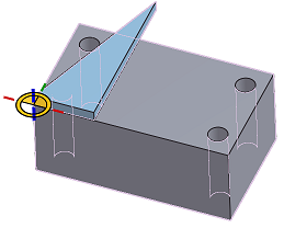
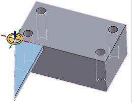
![]() 重新定向副軸工具以 90 度的增量調整方位。
重新定向副軸工具以 90 度的增量調整方位。
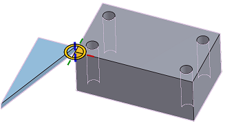
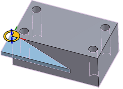
- 解出按鈕會重生成處理中的結合以及所有結合的移動,所以您可以查看變更如何影響整個組合件。
結合類型會指定移動的行為。
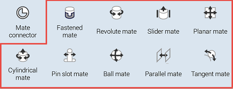
在 Onshape 中的結合與在傳統 CAD 系統中的結合有所不同。在兩個實例間的移動 (自由度) 是內嵌於結合的情況下,您在任兩個實例間可能只需要有一個 Onshape 結合。
您可以將圖元與組合件的原點結合。您也可以使用環境選單來固定一個圖元以測試所指定結合的移動情況。圖元包括:零件、組合件、次組合件、草圖與曲面。
結合是在結合對話方塊中定義的:
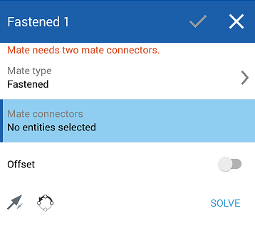
選擇要建立的結合類型,然後選擇隱含或明確的結合連接器 (一個零件上選擇一個)。
結合類型 - 結合類型欄位顯示您要使用的結合類型。輕觸來開啟結合類型的清單,然後輕觸來選擇一個項目。
結合連接器 - 接下來的結合連接器的區域是以藍色強調顯示。這表示需要有來自圖形區域的選取項目。必須選擇兩個結合連接器 (一個結合的實例上要有一個)。
偏移 - 輕觸來設定偏移距離以定義要結合零件間的固定空間。
限制 - 輕觸來設定移動的距離限制。
![]() - 反轉主軸,即實例的 Z 方位。
- 反轉主軸,即實例的 Z 方位。
![]() - 重新定向副軸;輕觸即可以 90 度旋轉實例的象限方位 (在 XY 平面上)。
- 重新定向副軸;輕觸即可以 90 度旋轉實例的象限方位 (在 XY 平面上)。
解出 - 輕觸以解出包括目前這個結合的所有組合件結合。
除了球面、緊固與相切結合之外,您可以指定所有結合的移動限制。
在允許限制的結合 (轉動、滑動、平面、圓柱與銷槽) 對話方塊內,開啟 [限制] 的按鈕,限制的欄位隨即出現。
輸入所要的限制條件,然後輕觸解出來視覺檢視變更。
為下列的結合類型提供於組合件操作過程中將一個圖元從另一個圖元偏移:
- 平面偏移 - 沿 Z 軸
- 滑動偏移 - 沿 X 與 Y 軸
- 旋轉偏移 - 沿著 Z 軸
- 銷槽偏移 - 沿 Z 軸
- 緊固偏移 - 沿 X、Y、和 Z 軸
您也可以拖曳圖元然後在圖形區域中觀察距離值。這樣可以幫助決定在對話方塊中要輸入的指定值。
您可以在組合件的數值欄位中使用表達式與三角函數。
除了在組合件清單中出現外,結合在圖形區域中也有指標。您可以在組合件清單中隱藏圖元與結合連接器來更清楚地看到結合指標。這些指標提示了結合定義的動作類型以及目前的狀態:藍色/白色表示良好的結合,灰色表示是抑制或非啟用的,紅色則是有問題 (仍可編輯抑制的結合)。
![]()
![]()
![]() 緊固
緊固
![]()
![]()
![]() 轉動
轉動
![]()
![]()
![]() 滑動
滑動
![]()
![]()
![]() 平面
平面
![]()
![]()
![]() 圓柱
圓柱
![]()
![]()
![]() 銷槽,在槽的方向上有箭頭
銷槽,在槽的方向上有箭頭
![]()
![]()
![]() 球面
球面
![]()
![]()
![]() 相切
相切
![]()
![]()
![]() 平行
平行
![]()
![]()
![]() 群組
群組
更多視覺查看結合的提示:
- 兩指輕觸來開啟環境選單,輕觸全部顯示來顯示列於實例清單中的所有項目,包括結合連接器與結合指標。
- 輕觸實例清單中的一個結合。
- 兩個實例間僅有一個結合。
- 固定一個圖元與套用結合有所不同。「固定」 (在環境選單中) 是針對套用固定於其中的組合件的;並不會繼續存在於圖元被插入至的另一個組合件中。
- 結合會將兩個零件實例以某種關係相互定位,使每個實例上的結合連接器對齊。
結合之前

結合之後

- 最初的位置通常是最佳的猜測。有兩個工具可更正位置:
![]() 反轉主軸工具會反轉主軸 (Z) 的方位。
反轉主軸工具會反轉主軸 (Z) 的方位。


![]() 重新定向副軸工具以 90 度的增量調整方位。
重新定向副軸工具以 90 度的增量調整方位。


- 解出按鈕會重生成處理中的結合以及所有結合的移動,所以您可以查看變更如何影響整個組合件。
結合類型會指定移動的行為。
關於「學習中心」的其他資源,請參照此處的技術簡報文章:Mating Basics (需要有 Onshape 帳戶) 與 Advanced Mating Techniques (需要有 Onshape 帳戶)。
