結合連接器
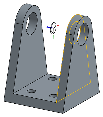
Mate connectors are local coordinate system entities located on or between entities. They are used within a mate to locate and orient instances with respect to each other. You can also use mate connectors to create planes.

快速鍵:Ctrl+m
Shortcut: k (to show/hide mate connectors)
Mate connectors are local coordinate system entities located on or between sketches, parts, curves, or surfaces in Part Studios and on or between entities in assemblies. They are used within a mate to locate and orient sketch, part, curve, or surface instances with respect to each other.
Two part or surface instances are positioned in an assembly by creating a mate. The two instances are positioned by aligning a mate connector defined on one instance with a mate connector defined on the other instance.
The Z-axis of a mate connector can be used for Features that require the selection of an axis.
可以用明確或隱含的方式來定義結合連接器:
- Explicit mate connectors:
- Defined using the Mate connector tool in the toolbar in an Assembly or in a Part Studio
- 會被列在特徵清單中的最高層級上
- 可以在建立結合的過程中從特徵清單中被選取
- Implicit mate connectors:
- Defined while creating a mate, in an assembly and some features in a Part Studio
- Listed at a sub-level in the Feature list in an assembly, beneath the mate in which it is used
- Cannot be selected from the Feature list during the creation of mate
- 可於編輯其他特徵時建立
當在多個結合中使用同一個結合連接器時,會在特徵清單中列出使用該結合連接器的第一個結合,且僅列出結合連結器一次 (如果是隱含的結合),或結合連接器會以最上層的特徵在清單中出現。
Use the shortcut key k to hide/show mate connectors.
To learn more about mates, see Mates. To learn about mates and mate connectors, watch the video below.


讓我們看一下如何在 Onshape 中將結合加入到組合件上。切換到這個空白的 Assembly 分頁,然後插入來自 Part Studio 中的所有項目。所有的零件都可完全自由移動,並有全部的自由度。一開始請先固定一個零件來完全移除其自由度,使得其他零件可相對於其結合。要完成此操作,請在圖形區域或特徵清單中的一個零件上按右鍵,然後選擇 [固定]。任何被固定的零件在特徵清單中會有這個圖示。
Onshape defines mates based on the intended behavior that you would like as a result, such as fastened, revolute, slider, planar, cylindrical, pin slot, ball, and parallel. To have this part slide along the base, select the Slider Mate. Onshape prompts you for a mate connector. These are at the heart of adding mates. Roll your pointer over any face, and small dots appear. These are locations on faces where you establish mate connectors. When rolling over one of these dots, a small triad appears. In addition to being locations on faces and edges, mate connectors act as a coordinate system with their own x-, y- and z-axes. The orientation of the axes is important, particularly for certain types of mates. To slide this part along the blue z-axis of the triad, orient the blue axis normal to the edge of the part and click to snap it into place.
For the second ,ate connector, roll over the faces of the other part and the same principle applies. Pay attention to the orientation of the triad. When clicked, the part snaps into place. Notice there are icons to flip the primary and secondary axes in case you need to make any adjustments and obtain the correct results. With this single mate added using mate connectors, you can remove several degrees of freedom in just a few steps.
The Slider Mate is now listed in the features list. Double-click to open it and make adjustments to the mate. For example, use the dropdown to change this mate to any other mate type, or to redefine any of the mate connectors.
To fasten the spindle inside the shaft, click the Fastened Mate. This mate type removes all degrees of freedom between any two mate connectors, so they are bonded together. For these mate connectors, select the point on the face inside the shaft and on the face of the spindle. Rotating one of the parts rotates them both.
Next, mate the screw with the sliding jaw. Use the Revolute or Cylindrical Mate. Revolute removes an additional degree of freedom than Cylindrical does. Click Cylindrical Mate. Roll over the cylindrical face of the jaw. There are three default mate connector locations along its axis. Select the point at the rear of the cylinder and repeat the process for the shaft. When the parts snap into position, you may notice that previously added mates are not solved. In these instances, click the Solve button. Finally, click the checkmark to close the Mate dialog.
At this point, the spindle is free to rotate about the mate connector and is also free to move along the axis. This is the way the Cylindrical Mate operates. Double-click the Cylindrical Mate to open its dialog and change it to Revolute. Now, moving the spindle rotates it without moving it away from the mate point on the jaw.
Keep in mind that you can use the mate connector tool to precisely define the location and orientation of mate points ahead of time, without having to create the ,ates. You can even add mate connectors to parts in your Part Studio so they are available when those parts are inserted into your assemblies.

- 按一下
。
- Choose between creating a mate connector on a sketch or part (entity) or between sketches/parts:
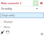
- On entity - Create a mate connector on a part or sketch:
- Between entities - Create a mate connector halfway between two entities on the part or sketch:
- On entity - Create a mate connector on a part or sketch:
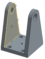
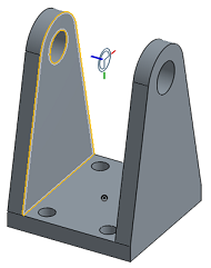
- Select a point on the part or sketch for the mate connector:
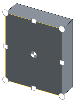
- Roll over any face to activate the potential mate connectors and select a point.
- Or click anywhere on a face to automatically place the mate connector at the centroid point.
您也可以選擇原點來做為圖元;可以在圖形區域或實例清單中選擇原點。
- 如果需要,請指定選項 (如下方的選項範例所示)。
- 按一下
。

With the Mate connector dialog open, moving the cursor over a part "wakes up" default inference points and the inference point closest to the cursor highlights as a mate connector. As you continue to mouse over the sketch or part, different default inference points appear.
To lock mate inferences when you see the one you want to select, hold the Shift key when mousing.
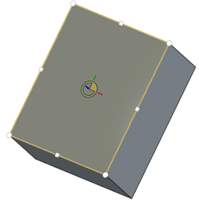
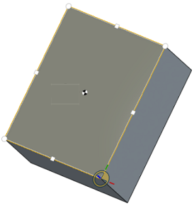
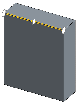
零件或草圖的每個面與邊線都有預設的推斷點:
- 在形心
- 在中點
- 在角落
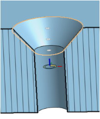
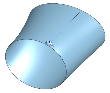
- At the virtual sharps of conical faces:
在圓錐面上、中、下與虛擬交角 (圓錐面側邊沿伸時的交點) 的推斷點
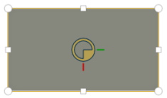
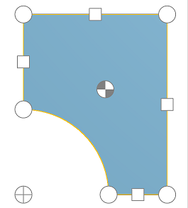
- At the centroids of any region contained in a planar face (for example, holes, and slots)
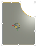
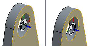
Before the default Mate connector is highlighted at the centroid (left), you might see the centroid point icon (right):
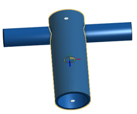
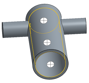
對於圓柱面,推斷點會出現在圓柱與部分圓柱面的軸上:
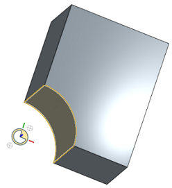
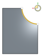
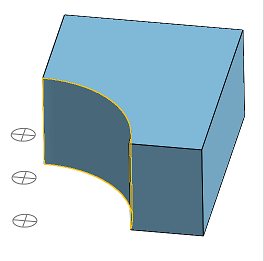
Select a planar face that has a partial cylindrical edge, and the Mate connector inference points include the centroid of the axis:
Hover over the edge of the partial cylindrical face, and the default Mate connector appears at the centroid of the axis:
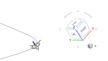
If you select a curve endpoint or control point, the Mate connector is aligned with the global Z-axis (shown in blue):
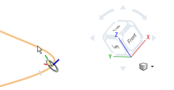
If you select the curve itself, the Mate connector is aligned tangent to the curve at the closest implicit end, control, or midpoint
To zero in on a specific inferenced point or default mate connector without waking up others as you move the cursor, use the SHIFT key to prevent other mate connectors from appearing.

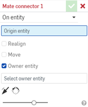
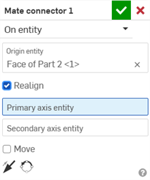
Check Realign to change the orientation of the mate connector along a primary and (optionally) a secondary axis.

Move the mate connector a specified distance in a specified direction. The fields are presented in this order:
- X 平移
- Y 平移
- Z 平移
You can also use the Rotate field to specify a rotation of a specified number of degrees.
You can use expressions and trigonometric functions in numeric fields in assemblies.
反轉結合連接器的主軸
將主軸反轉 180 度。
重新定向結合連接器的副軸
使用 X/Y 座標來一次移動主軸四分之一圓。

The inference points for potential mate connectors available when you select an edge or face are:
-
平坦面 - 在每個頂點、弧心、邊線中點平行於面,以及面形心
-
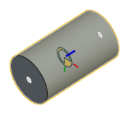
圓柱面 - 在中間與尾端垂直於面的軸
-
線性邊線或草圖線 - 在中間與尾端垂直於直線
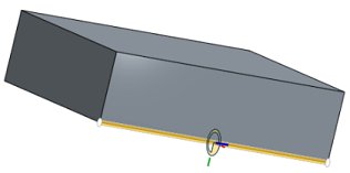
-
圓形邊線或草圖圓 - 在中間與尾端垂直於直線
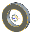
-
Curve endpoint and control point - Aligned with the global Z-axis
-
Curve - Tangent to the curve at the closest end, control, or midpoint
-
Vertex - Normal to the given face

Once created, you are able to hide or show mate connectors in both Part Studios and assemblies:
- Use the context menu in the Feature list (Hide, Hide other Mate connectors/Show, Show all Mate connectors)
- Hide other Mate connectors hides all Mate connectors except the one you have selected.
- 使用在特徵清單中的
圖示來隱藏某一特定的結合連接器。
- Hiding/showing mate connectors in a Part Studio or assembly is exclusive to the Part Studio or assembly. Mate connectors hidden in a Part Studio are visible when inserted into the assembly. You have the ability to view mate connectors in a Part Studio and keep them hidden in the assembly, and vice versa.

- If the behavior is not what you expected, try flipping the primary and/or secondary axis on the mate connector.
- Use the SHIFT key to keep the mate connectors you want visible as you move the pointer to select one. This can be useful when the inferenced point for potential mate connector you want is on or near an edge.
- All mate connectors are listed in the Feature list; you are able to hide/show them, edit and adjust, change, and use different orientations of the connectors.
- You can also select and hide/show mate connectors when working in context.
- A mate connector may be created in both the assembly and the Part Studio. Creating a mate connector in the Part Studio has three advantages:
- You are able to select the origin from the Feature list in a Part Studio when defining a mate connector.
- You are able to reference sketch entities in the Part Studio. This gives you the ability to define the mate connector in more positions than are possible in an assembly.
- A mate connector defined in a Part Studio is available for reuse on every instance of that part in every assembly in which it is instanced.
- When creating a mate connector in the Part Studio, there is an additional option in the Mate connector dialog called Owner Entity.
Mate connector dialog in Assembly
Mate connector dialog in Part Studio
In a Part Studio with multiple parts , it can be unclear which part owns the Mate connector. Use the Owner Entity field to specify which sketch, part, or curve owns the Mate connector, or leave the Owner Entity field blank to create an ownerless Mate connector.
- 如果結合連接器是在 Part Studio 中複製排列的零件,在插入 Part Studio 時,會將結合連接器加入到組合件中。如果在將 Part Studio 插入到組合件中時沒有看到您的結合連接器,請確定零件是列為結合連接器的所屬圖元。
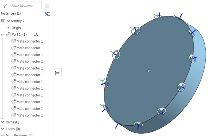
結合連接器是在草圖、零件、曲線或曲面上或其間的局部座標系統圖元,用於結合中以在草圖、零件、曲線或曲面實例之間相互定位與定向。您也可以使用結合連接器來建立平面。

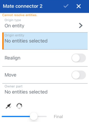
- 輕觸「結合連接器」工具。
- Select origin type:
- 在圖元上 - 在一個零件或草圖上建立結合連接器。
- Between entities - Create a Mate connector halfway between two entities on the sketch, part, curve, or surface.
- 選擇起源圖元。
- 選擇性地切換來重新對齊。
如果要對齊,請選擇主軸與副軸圖元。
- 選擇性地切換來移動。
如果您要移動,請指定 X、Y 與 Z 值。
同時選擇旋轉軸與指定旋轉角度。
- 選擇所屬圖元。
- 輕觸核取記號。
You can also create mate connectors in Part Studios while editing other features. See the appropriate feature tool topic for more information.

Toggle on Realign to change the orientation of the mate connector along a primary and (optionally) a secondary axis.
選擇結合連接器要重新對正的主軸與副軸。

Move the mate connector to a specified distance in a specified direction. The fields are presented in this order:
- X 平移
- Y 平移
- Z 平移
您也可以使用旋轉軸並指定度數來旋轉結合連接器。
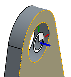
Once created, you are able to hide or show mate connectors in both Part Studios and assemblies:
- Use the context menu in the Feature list (Hide, Hide other Mate connectors/Show, Show all Mate connectors)
- Hide other Mate connectors hides all mate connectors except the one you have selected.
- 使用特徵清單中的隱藏/顯示圖示 (眼睛圖示) 來隱藏特定的結合連接點。
- Hiding/showing mate connectors in a Part Studio or assembly is exclusive to the Part Studio or assembly. Mate connectors hidden in a Part Studio are visible when inserted into the assembly. You are able to view mate connectors in a Part Studio and keep them hidden in the assembly, and vice versa.

結合連接器是在草圖、零件、曲線或曲面上或其間的局部座標系統圖元,用於結合中以在草圖、零件、曲線或曲面實例之間相互定位與定向。您也可以使用結合連接器來建立平面。

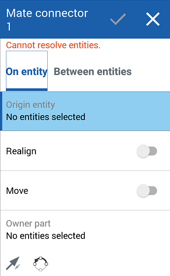
- 輕觸「結合連接器」工具。
- Select origin type:
- 在圖元上 - 在一個草圖、零件、曲線或曲面上建立結合連接器
- Between entities - Create a Mate connector halfway between two entities on the sketch, part, curve, or surface.
- 選擇起源圖元。
- 選擇性地切換來重新對齊。
如果要對齊,請選擇主軸與副軸圖元。
- 選擇性地切換來移動。
如果您要移動,請指定 X、Y 與 Z 值。
同時選擇旋轉軸與指定旋轉角度。
- 選擇所屬圖元。
- 輕觸核取記號。

Toggle on Realign to change the orientation of the mate connector along a primary and (optionally) a secondary axis.
選擇結合連接器要重新對正的主軸與副軸。

Move the mate connector to a specified distance in a specified direction. The fields are presented in this order:
- X 平移
- Y 平移
- Z 平移
您也可以使用旋轉軸並指定度數來旋轉結合連接器。
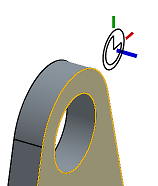
Once created, you can hide or show mate connectors in both Part Studios and assemblies:
- Use the context menu in the Feature list (Hide, Hide other Mate connectors/Show, Show all Mate connectors)
- Hide other Mate connectors hides all mate connectors except the one you have selected.
- 使用特徵清單中的隱藏/顯示圖示 (眼睛圖示) 來隱藏特定的結合連接點。
- Hiding/showing mate connectors in a Part Studio or assembly is exclusive to the Part Studio or assembly. Mate connectors hidden in a Part Studio are visible when inserted into the assembly. You are able to view mate connectors in a Part Studio and keep them hidden in the ssembly, and vice versa.
關於「學習中心」的其他資源,請參照此處的技術簡報文章:All the ways to use Mate connectors (需要有 Onshape 帳戶)。