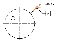
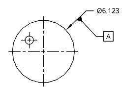
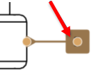
使用基準來在工程視圖中建立與放置與關聯性的基準符號,通常是將基準放置在線性或圓形邊線上來辨識為零件的基準面:
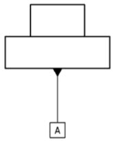
Datums and Geometric tolerances are an integral part of communicating manufacturing variation within a drawing.
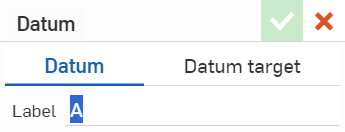
Add a Datum to the drawing. Stay in the Datum tab to quickly place datums along drawing view edges. The Label field automatically populates with a letter, but it is customizable. Click a view edge to attach the Datum symbol with a leader. Click again to place it. The tool stays active for continuous placement of additional symbols.
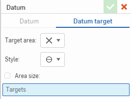
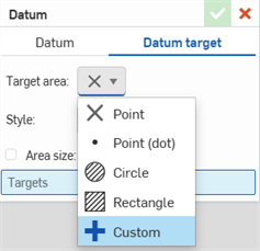
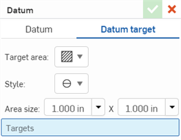
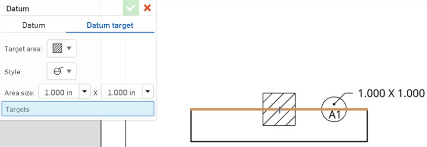
Click the Datum target tab to define a specific area to apply another datum. In the Target area dropdown, select a shape. In the Style dropdown, select a callout. Check Area size to specify the target shape. A diameter defines the size of an X, Point, or Circle, while the size of a Rectangle is defined by side lengths. Select the precision from the dropdown. Enter a value for Diameter. Click a view location to attach the symbol. Click again to place it.
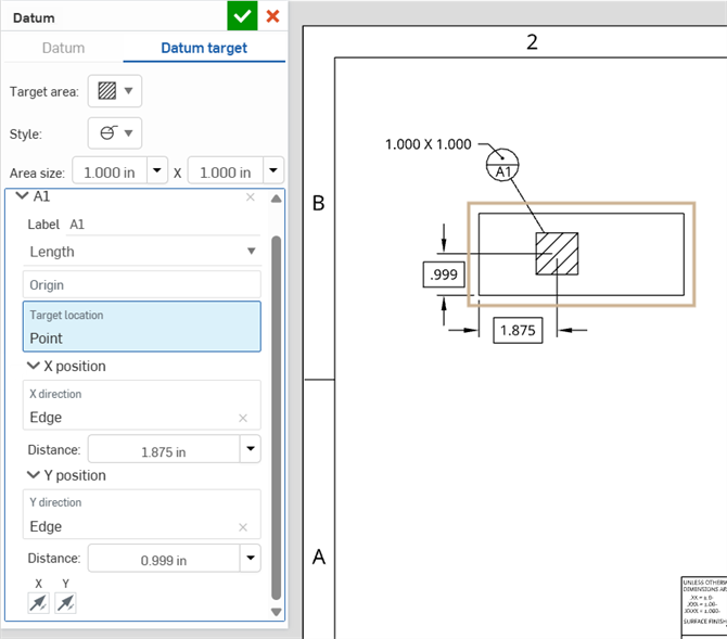
Accept the dialog or choose to add dimensions using Targets. Use the Origin target location when there is a vertex where the X and Y axis intersects, or define the X and Y directions by selecting edges in the view. Click the X and Y opposite direction arrows to flip the dimension placement. Accept the Datum.
Reposition by selecting the grip points at the base or dragging the end. Edit from its right-click context menu or double left-click.
Add a Geometric tolerance. Select the tolerance Symbol, enter the tolerance, and input any needed Datums. Insert a Leader, add Symbols, and add Geometric tolerance modifiers such as maximum material condition. Select any combination of Free state, Tangent plane, or Projected tolerance zone.
Add additional frames by clicking the Add frames icon. Successive frames provide a new option in the Symbols dropdown for Composite. This spans the Symbol across both frames. Remove extra frames by clicking the Remove last frame icon.
Click anywhere on the sheet or click a dimension to place the Geometric tolerance. Continue placing additional Geometric tolerances or accept the dialog. When placed on a dimension, it is snapped to the dimension, following it when moved. Drag a Geometric tolerance off a dimension to unsnap it. Drag it on a dimension to snap it.
Edit a Geometric tolerance from its right-click context menu or double left-click to open the edit dialog.
- 按一下 。
- 在對話方塊中輸入所需的標籤。
- 按一下來選擇零件視圖的邊線,從邊線朝外拖曳來建立基準線。
- 按一下來設定基準符號。
在移動滑鼠的操作中,您會在游標經過靠近其他圖元時,看到細虛線的出現。這些是您可以用來對齊尺寸的推斷線;當您看到尺寸與虛線對齊時只要按一下即可。
-
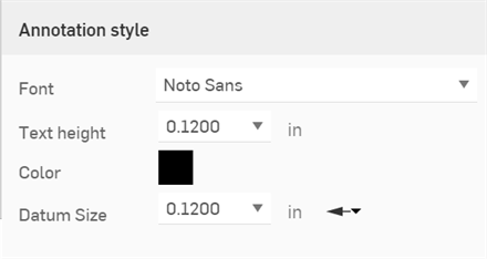
Click on the datum you want to style, then click the Styles panel icon on the right side of the page:
-
編輯「字型」、「文字高度」、「色彩」與「基準大小」:
- 按一下 。
- 按一下基準目標。
- 從「目標區域」下拉清單中選擇目標的形狀。
- 從下拉清單中選擇目標標註的「樣式」。
- Specify the Area size for the target:
(Optional) Point (X): Check the Area size box and specify the diameter. Select the precision from the dropdown.
(Optional) Point (dot): Check the Area size box and specify the diameter. Select the precision from the dropdown.
- Circle: Specify the diameter. Select the precision from the dropdown.
- Rectangle: Specify the side lengths. Select the precision from the dropdown.
- 按一下來在工程圖中放置目標。
- 再按一下來放置目標標註。
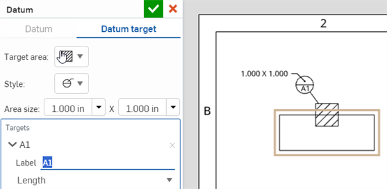
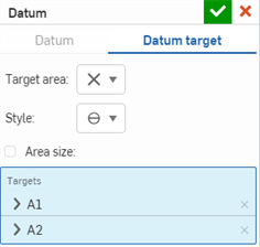
- Change the target Label, if necessary. Adding additional targets in the Datum target dialog will increment the label digit (A2, A3, A4, etc.). Adding new targets will increment the label letter (B1, C1, D1, etc).
- Next, you'll select the origin for the target. The exact location of the target will be determined relative to this origin point. You can specify this location either by distance or angle from the origin.
- To define the target location by distance:
- Select Length from the dropdown.
- Click to place the origin.
- Specify the distance of the target's X-Position and Y-Position from the origin.
- Optionally, click the Distance dropdowns to set precision.
- 使用 X 與 Y 箭頭按鈕來變更目標相對於原點的方位。
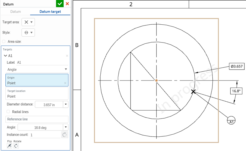
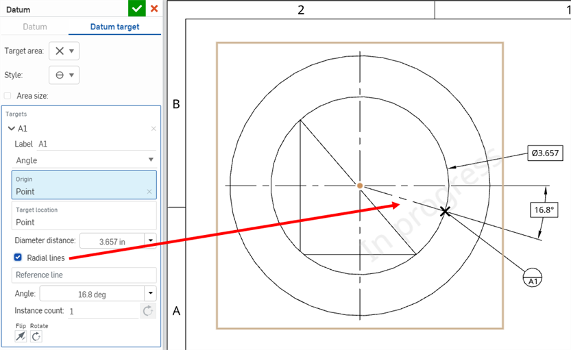
- To define the target angularly:
- Select Angle from the dropdown.
- Click to place the origin at the center of a circle or arc.
- Specify the target's Diameter distance from the origin. The target will be placed half this distance (i.e., the radius distance) from the origin.
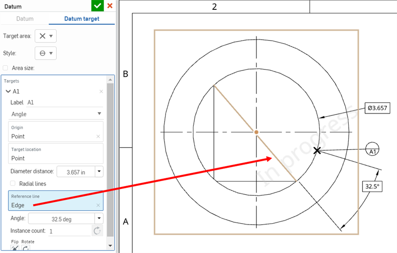
- Next, specify the angle for the target. The target will be placed at this angle from horizontal.
- Optionally, click the Diameter distance and Angle dropdowns to set precision.
- Click the Radial lines option to display a line from the origin to the target.
- To specify a different reference than horizontal, click the Reference line field and select an edge. The target will be placed at an angle from this line.
- Use the Flip and Rotate buttons as needed to change the orientation of the target relative to the origin.
- Add instances of the datum target with the Instance option. All instances will be evenly spaced along a 360 degree arc. Click the Opposite direction button to order the instances counter-clockwise instead of clockwise.
- To define the target location by distance:
- Click in the Targets field of the Datum target dialog to add additional targets (you'll see the Click in space to add a target tooltip). All targets added in the dialog will start with the same preceding letter (i.e., A1, A2, A3, etc).
- 按一下核取記號來關閉「基準」對話方塊。
-
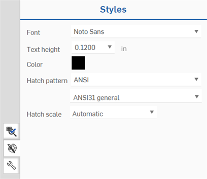
Click on the datum target you want to style, then click the Styles panel icon on the right side of the page:
-
Edit the Font, Text height, Color, Hatch pattern, and Hatch scale:
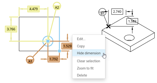
- Right-click the dimension you want to hide, and then click Hide dimension.
- Repeat for each dimension you want to hide.
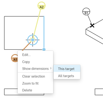
- To show hidden dimensions, right-click the target label, then select Show dimensions.
- To show only the dimensions for that target (A1 in the example below), click This target.
- To show all the dimensions for all targets associated with that label (A1 and A2 in the example below), click All targets.
- 在放置基準之後,您可以將基準拖曳至另一個位置:方法是按一下來選擇基準,然後拖曳。
- You can drag a datum closer to or farther away from its placement point on the drawing, and the extension line adjusts appropriately.
- You can group datums with callouts. See Callout (Balloon) for more information.
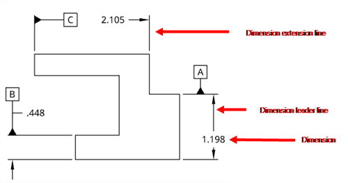
- 您可以將基準與尺寸界線相關聯:
- To change the label, click to select the datum, then double-click in the highlighted square:
系統會開啟「基準」對話方塊,然後您可以變更標籤。您也可以在「屬性」面板、「註記」分頁、「箭頭」設定中變更所有箭頭的三角形屬性設定。
-
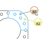
When selecting a Datum target in a series, the target and associated face is highlighted blue. Any other datum in the series are secondarily highlighted yellow:
-
You can attach datum symbols to radius and diameter dimensions. You cannot, however, attach datum symbols to radius or diameter dimensions that can be converted to a foreshortened dimension (for example, a dimension in detail view).