 鑽孔
鑽孔
![]()
![]()
![]()
在 Part Studio 中提供此功能
在草圖點、圓心和結合連接器上建立簡易直孔、沉頭孔、和埋頭孔。
在 Onshape 中有兩種建立鑽孔的方法。第一個建立鑽孔方法是建立草圖,然後套用使用「移除」選項的「擠出」特徵。第二個方法則是利用「鑽孔」特徵。每個方法各有其利弊。
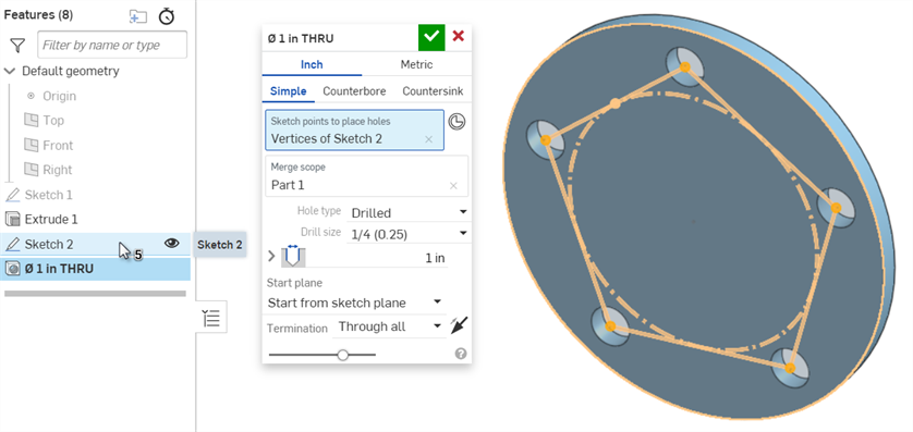
「鑽孔」特徵會在任何選取的草圖點上放置鑽孔,將鑽孔中心與該點對齊。可接受的草圖點包括獨立點、頂點與圓的中心點。從「特徵」清單中選擇草圖來包括所有非建構的頂點。
您也可以使用隱含與明確的結合連接器來導出鑽孔的位置。若要選擇一個隱含的結合連接器來做為鑽孔的中心點,按一下「選擇結合連接器」圖示,然後在圖形區域中選擇一個隱含的結合連接器。選擇性地點按藍色選取區域中的「結合連接器」圖示來進一步編輯隱含的結合連接器。
按一下「合併範圍」欄位來指定要切除的零件。
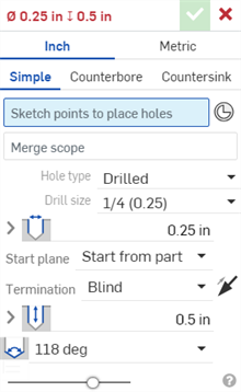
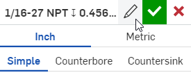
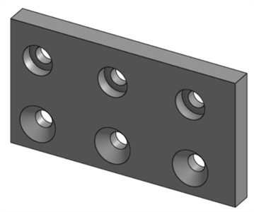
例如,建立煞車槓桿軸上的一個鑽孔。從特徵工具列中開始一個新的「鑽孔」特徵。選擇「公制」分頁。有三種可用的鑽孔類型:「簡易」、「沉頭孔」、與「埋頭孔」。
使用「鑽孔」類型來建立簡易直孔。其他的鑽孔類型包括「餘隙」、「螺絲攻」、與「PEM®」。當需要時,「鑽孔」可讓您指定鑽孔大小並編輯直徑。 「餘隙」、「螺絲攻」、與「PEM®」鑽孔可允許進一步的自訂,對每種鑽孔類型會各別有其他的欄位。
同時設定鑽孔的「起始平面」與終止。根據預設,鑽孔會從零件開始。若要指定一個不同的起始平面,請選擇「從草圖平面開始」或「從所選平面開始」。
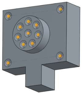
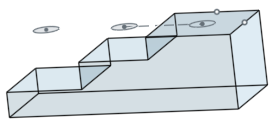
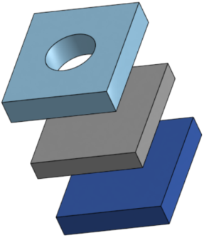
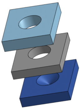
此處說明的範例是要在這個階梯狀零件上建立一些鑽孔。一開始草圖是位在中心階梯的面上。當使用「從零件開始」做為起始選項時,鑽孔明顯地穿過前兩個階梯。不過最後一個階梯是高過於草圖平面的。在剖面檢視中,明顯地看出特徵建立了鑽孔但並未穿過草圖平面上方。「從零件開始」僅會在與鑽孔相同的方向上調整起始平面。因為草圖平面已與零件相交,因此「從零件開始」與「從草圖平面開始」會產生相同的結果。
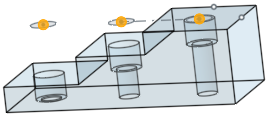
為了進一步說明起始選項,我們把草圖移動到最上方階梯上面 1mm 的平面上。現在簡易直孔就會穿過三個階梯。
變更鑽孔類型為「埋頭孔」,使用 M3 的大小,然後選擇「從零件開始」。鑽孔特徵會在三個階梯上切出 3mm 的完整外部深度。
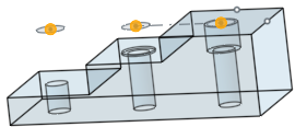
將「起始平面」變更為「從草圖平面開始」。現在僅有一個鑽孔會是埋頭孔。在仔細檢查時,會發現埋頭孔的深度是小於完整的 3mm (當選擇「從零件開始」時特徵會切割的深度)。這是因為草圖平面是在零件表面上的 1 mm 處。
選擇「從所選平面開始」並將階梯的頂面指定為鑽孔的起始平面。埋頭孔即會在最上方階梯中切出完整的深度。
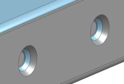
在煞車槓桿中,顯示 Sketch 1 並將較大圓的中心選擇做為鑽孔的位置。指定 14 的鑽孔大小,對應產生 14mm 的鑽孔。在選取了「從零件開始」的情況下,由於草圖平面的位置,鑽孔並不會穿過整個零件。要解決這個問題,請將「起始平面」變更為「從所選平面開始」,然後選擇外側面。
另一個方法需要使用隱含的結合連接器。若要執行此操作,請隱藏 Sketch 1 然後按一下「選擇結合連接器」。接著選擇在外側面上的隱含結合連接器。
由於ˊ這個範例只有一個零件,系統會自動移入合併範圍。
最後請設定鑽孔的「終止」。「完全貫穿」會使鑽孔切穿「合併範圍」內的所有零件。「給定深度」會在指定的尺寸處終止鑽孔。
「成形至下一幾何」會切穿至碰到的下一個或多個面,並會有從鑽孔頂端偏移的選項。切換「相反方向」箭頭來反轉偏移。
「成形至圖元」會切割至所選圖元,像是面或是平面。這個選項確保會整個直徑是切割到圖元的。如果鑽孔的「頂錐角」樣式不是平的,則頂端會延伸超出所選的圖元。「從頂端偏移」可讓您編輯鑽孔的切割以避免頂端的侵入或延伸鑽孔的切割。
此外,可以展開「直徑」與「深度公差控制」向來自訂鑽孔的公差與精度。對於「埋頭孔」與「沉頭孔」鑽孔會有更多的公差控制項。
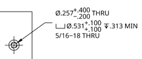
在建立工程圖時,使用「鑽孔」特徵相較於擠出除料的優勢明顯可見。鑽孔標註註記僅能加入到使用「鑽孔」特徵建立的鑽孔上。無法將鑽孔標註附加到「擠出」除料中。
當在組合件中放置標準內容時,「鑽孔」特徵又有另一個優勢。在自動調整硬體或扣件大小時,自動調整大小的功能會決定直徑與螺紋規格。自動調整大小無法偵測使用「擠出移除」特徵建立鑽孔的長度與螺紋長度。
- 建立一個有草圖點的草圖,然後按一下特徵工具列上的「鑽孔」特徵圖示 (
 )。
)。
-
選擇測量單位,可以是「英吋」或「公制」。
- 選擇一個鑽孔樣式:
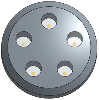
- 簡易 - 一個相同直徑的鑽孔。
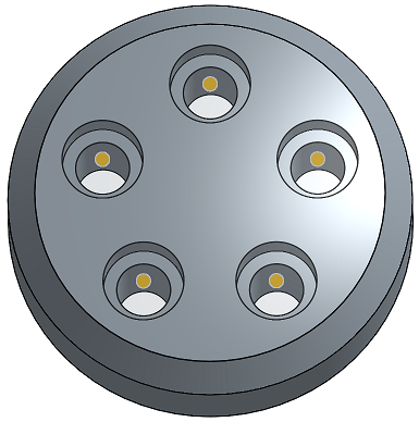
- 埋頭孔 - 圓柱平底鑽孔,可擴大另一個同軸鑽孔。
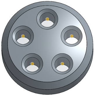
- 沉頭孔 - 頂端有圓錐離隙的一個鑽孔。
- 在草圖中選擇要放置鑽孔中心的點 (包括幾何的轉角、線端點、樣條點、圓心等等)。
- 您可以用方塊選擇多個點。
- 您可以按一下「結合連接器」圖示 (
 ) 來將隱含的結合連接器選取或建立為點而不是草圖點:
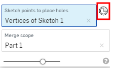
在選擇了結合連接器之後,按一下「結合連接器」圖示 (
) 來開啟對話方塊以編輯結合連接器: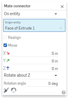
- 或者,在草圖上按一下來自動選擇草圖上所有的點,並不包括用做為幾何建構線的點。
- 在對話方塊中已選擇了合併範圍欄位的情況下,選擇包含鑽孔的零件。
- 根據您的需求從下列鑽孔類型與鑽孔類型規格中選擇。取決於您的選擇,並沒有為所有鑽孔類型提供全部的鑽孔類型規格:
- 鑽孔 - 建立一個鑽孔。
- 鑽孔大小 - 從下拉式清單中選擇鑽孔大小。
- 餘隙 - 建立一個餘隙鑽孔。
- 大小 - 從下拉式清單中選擇餘隙大小。
- 緊固件配合 - 從「緊密」、「自由」、「緊密 (ASME)」、「正常 (ASME)」與「鬆動 (ASME)」中選擇
- 螺孔 - 建立一個螺絲攻鑽孔。
裝飾螺紋是不影響幾何的螺紋視覺呈現。Onshape 會在 Part Studio 中顯示外部螺紋與螺絲攻鑽孔的裝飾螺紋。因為系統不需要重新計算螺紋幾何,因此會有更快的迭代和再生。同時可使用鑽孔/螺紋標註在工程圖中註記裝飾螺紋。
- 螺絲攻類型 - 選擇直式螺絲攻、直式管螺紋攻 (僅適用於公制)、或錐形管螺絲攻。取決於您在此處的選擇,下方的選項會有所不同。
- 螺紋類型 - (僅適用於「直式管螺紋攻」) 為 British Standard Pipe Parallel (BSPP) 螺紋選擇 G,或為 British Standard Parallel 內部螺紋 (與錐形外螺紋配合時使用) 選擇 RP。
- 大小 - 從下拉式清單中選擇螺絲攻鑽孔大小。
- 螺紋/英吋 - 從下拉清單中選擇每英吋螺紋數 (tpi) 設定。
- 緊固件配合 - 只有在「合併範圍」欄位中選取 2 個或更多零件時,適用於「直式螺絲攻」類型。可從無、緊密、自由、緊密 (ASME)、正常 (ASME)、鬆動 (ASME) 中選擇。
- 螺紋類別 - 選擇性地選取核取方塊以開啟或關閉「螺紋類別」。開啟時,下拉式清單中會顯示適當的「英吋」或「公制」類別。
- PEM® - PennEngineering® 緊固件。埋頭孔與沉頭孔無法使用此選項。
- 緊固件 - 從「壓鑄螺帽」、「壓鑄螺母」、「壓鑄螺柱 & 銷」中選擇
- 緊固件類型 - 從 S™/SS™/CLS™/CLSS™/SP™ nuts、CLA™ free running locknuts、S-RT™ Free-running locknuts、SL™ TRI-DENT® Prevailing torque locknuts、Self-clinching nuts, H™ Nuts/HNL™ Prevailing torque locknuts、SH™ Hard panel nuts、SMPS™/SMPP™ Nuts 中選擇。
- 大小 - 從下拉式清單中選擇螺絲攻鑽孔大小。
- 緊固件配合 - 餘隙。
- 鑽孔 - 建立一個鑽孔。
- Enter a Diameter value for the hole.
選擇性地按一下公差選項圖示 (
 ),然後按一下參數左側的下拉箭頭圖示 (
 ) 來設定公差精度和類型。詳細資訊請參考公差選項。
 - 選取鑽孔的「起始平面」:
- 從零件開始 - 鑽孔是從零件面開始。
- 從草圖平面開始 - 鑽孔是從草圖平面開始。
- 從所選平面開始 - 鑽孔是從選取的平面開始。
- 鑽孔起始平面或結合連接器 - 選擇鑽孔開始處的圖元 (平面或結合連接器)。
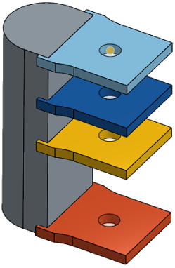
這些選項可讓您控制當於不同高度開始鑽孔時,深度會在零件上的相同位置上結束。例如,鑽孔的所有草圖點都在同一平面上:
對於有 1 英吋深度的埋頭孔,當鑽孔不是從草圖平面開始時,較短的鑽孔會僅包含埋頭的部分,而較深的鑽孔則會包含埋頭與螺栓:
但當鑽孔是從草圖平面開始時,則會先放置螺栓,埋頭的部分則會被縮短:
同樣的情形也適用於沉頭孔。簡易直孔僅會調整深度。
- 選擇「終止」(結束) 型態。對於所有的終止結束型態,可按一下「相反方向」箭頭 (
 ) 來反轉鑽孔方向。
- 給定深度 - 鑽孔結束於所選零件的指定深度上。
- 深度 - 輸入鑽孔的深度值,包括埋頭孔或沉頭孔的深度。
選擇性地按一下公差選項圖示 (
),然後按一下參數左側的下拉箭頭圖示 () 來設定公差精度和類型。詳細資訊請參考公差選項。 - 埋頭孔直徑 - 為埋頭孔輸入鑽孔尖端的直徑值,以及可在上方給定深度 > 深度之下找到一樣的精度與公差控制項。
- 埋頭孔深度 - 為埋頭孔輸入擴大孔的深度值,以及可在上方給定深度 > 深度之下找到一樣的精度與公差控制項。
- 沉頭孔直徑 - 為沉頭孔輸入擴大孔的直徑值,以及可在上方給定深度 > 深度之下找到一樣的精度與公差控制項。
- 沉頭孔角度 - 為沉頭孔輸入鑽孔的角度值,以及可在上方給定深度 > 深度之下找到一樣的精度與公差控制項。
- 螺孔深度 - 為螺絲攻鑽孔以文件單位 (或指定其他單位) 輸入鑽孔的完整螺紋深度。精度與公差類型控制項有與上方所列深度公差控制項之下相同的選項。
- 螺絲鑽餘隙 - 對於給定深度的螺絲鑽,螺絲鑽深度底部與鑽孔底部之間的螺距長度數。
當選取「界限」或「偏差」的公差類型時,下限與上限可接受零與負值。如果經計算的下限大於計算後的上限,會出現一個錯誤。經計算的上限與下限可以是相同的。
- 深度 - 輸入鑽孔的深度值,包括埋頭孔或沉頭孔的深度。
- 成形至下一幾何 - 成形至下一個碰到的一或多個面。
- 從頂端偏移 - 核取以輸入從鑽孔尖端的偏移距離值。按一下「相反方向」箭頭 () 來反轉偏移。
- 深度 - 多個。
- 精度與公差類型控制項 - 與在上方給定深度 > 深度之下可找到的選項相同。
- 從頂端偏移 - 核取以輸入從鑽孔尖端的偏移距離值。按一下「相反方向」箭頭 (
- 成形至圖元 - 成形至所選圖元或結合連接器。
- 成形至一圖元或結合連接器 - 選擇圖元 (例如面或平面) 或結合連接器 ()。
- 從頂端偏移 - 核取以輸入從鑽孔尖端的偏移距離值。按一下「相反方向」箭頭 () 來反轉偏移。
- 深度 - 多個。
- 精度與公差類型控制項 - 與在上方給定深度 > 深度之下可找到的選項相同。
- 成形至一圖元或結合連接器 - 選擇圖元 (例如面或平面) 或結合連接器 (
- 完全貫穿 - 完全穿過在「合併範圍」中選取的零件。
- 螺絲鑽完全貫穿 - 對於螺絲攻鑽孔,保持核取來建立整個鑽孔長度的螺紋。取消核取以指定:
- 螺絲鑽深度 - 輸入自訂的螺紋深度。
- 精度與公差類型控制項 - 與在上方給定深度 > 深度之下可找到的選項相同。
- 螺絲鑽完全貫穿 - 對於螺絲攻鑽孔,保持核取來建立整個鑽孔長度的螺紋。取消核取以指定:
- 給定深度 - 鑽孔結束於所選零件的指定深度上。
- 選擇鑽孔的「頂錐角樣式」。選項有「118 度」、「135 度」、「平坦」或「自訂」來自行設定。
- 頂錐角 - 為自訂的鑽孔輸入頂錐角的值。
- 精度與公差類型控制項 - 與在上方給定深度 > 深度之下可找到的選項相同。
- 鑽孔特徵的名稱自動跟新以反映鑽孔的設定。
- 若要重新命名鑽孔,將游標移動至「鑽孔」對話方塊中的「名稱」欄位上暫留,然後按一下出現的鉛筆圖示。輸入新的名稱,接著按下 Enter。
- 若要將鑽孔名稱改回自動產生的預設,將游標移動至「鑽孔」對話方塊中的「名稱」欄位上暫留, 按一下鉛筆圖示,然後刪除「名稱」欄位中的所有輸入項,最後按下 Enter。
- 按一下核取記號圖示 (
 ) 來建立鑽孔。
一個相同直徑的鑽孔:
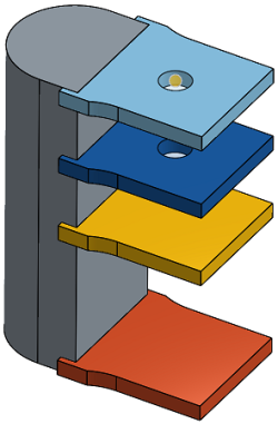
可以在啟用的鈑金特徵上建立鑽孔,也可以將埋頭孔或沉頭孔加入至鈑金中,如下所示:
取決於鑽孔特徵的合併範圍,鑽孔的計算可能會影響多個鈑金零件。在下方的範例中,使用相接觸的凸緣建立了 2 個鈑金零件。當將沉頭孔加入到模型,且在鑽孔「合併範圍」中同時包括兩個零件時,結果是沉頭孔會同時穿過兩個零件:
當使用「成形至下一幾何」或「成形至圖元」終止形態時,如果螺孔深度的輸入值大於最小的經計算鑽孔深度,則會重新調整螺孔深度,並會顯示下列的訊息:

-
如果經計算鑽孔深度大於輸入的螺孔深度,則不會重新調整螺孔深度。
-
如果經計算鑽孔深度小於輸入的螺孔深度,則會將螺孔深度值調整為經計算鑽孔深度值。
對於完全貫穿的鑽孔,在工程圖中的鑽孔/螺紋標註上對經計算鑽孔深度與螺孔深度值都會顯示 THRU:
- 會清除在草圖平面上的點與鑽孔之間的所有材料:
- 如果您改變草圖,會重新計算鑽孔特徵。
- 這個特徵包含會邏輯性推理來決定鑽孔的較佳開始深度,這對彎曲或不規則的曲面是相當有用的。此為系統預設。如果您要在草圖平面上開始鑽孔,請核取該方塊 (會有效地關閉開始深度的邏輯推理)。核取該方塊可讓您建立重疊的鑽孔。
- 在鑽孔特徵碰撞抵觸或鑽孔沒有完全位在目標零件的情況下,會在相對於草圖平面的 0 深度進行鑽孔。
-
如果標準中不提供埋頭孔、沉頭孔或螺絲鑽直徑,在值超出範圍的情況下,將會被重設。
-
在選取了兩個或多個零件的情況下,且螺孔 > 緊固件配合是設定為無之外的選項時,最開始的鑽孔是間隙孔,最終的鑽孔是螺絲孔 (這個方法取代棄用的在最後零件上的深度選項)。