 금속 판재 코너 분리
![]()
![]()
![]()
필렛이나 모따기를 적용하여 기존 금속 판재 부품의 모서리를 분리합니다. 코너 모서리 또는 꼭지점을 선택하고 코너 분리 유형과 거리를 지정합니다. 금속 판재 모델의 모든 플랜지와 조인트를 완성한 후에 이 피처를 사용하는 것이 좋습니다.
금속 판재 설계의 마지막 단계 중 하나는 부상과 걸림을 방지하기 위해 날카로운 코너를 분리하는 것입니다. Onshape의 금속 판재 코너 분리 기능은 선택한 코너에 필렛 또는 챔퍼를 추가하여 이 작업을 수행합니다.
금속 판재 파트의 최종 피처에 대한 코너 분리를 예약합니다. 코너 분리 피처가 적용된 후에는 조인트 유형과 스타일을 수정할 수 없습니다.
코너 분리는 벤드 릴리프 컷으로 인해 생성된 코너를 포함하여 판재 부품의 모든 코너에 적용됩니다.
새 코너 분리 피처를 시작합니다. 필렛 또는 챔퍼 탭을 선택한 다음 금속 판재 파트의 코너 또는 꼭지점을 하나 이상 선택합니다. 코너는 성형된 상태 또는 평평한 상태로 선택할 수 있습니다.
필렛의 경우 측정에서 반경 또는 너비를 선택합니다. 또한 필렛의 제어 옵션을 거리, 원추형 또는 곡률로 설정합니다.
반경 또는 너비 값을 설정하여 필렛의 치수를 지정합니다. 원추형 필렛의 경우 Rho 값을 설정합니다. 곡률 기반 필렛의 경우 크기를 설정합니다.
두 개의 반경이 함께 혼합된 필렛의 경우 비대칭을 선택하고 두 번째 반경을 입력합니다. 필요한 경우 비대칭 화살표 뒤집기를 전환합니다.
거리와 원추형 모두 모서리 오버플로우를 허용하는 옵션이 있습니다. 이 옵션을 선택하면 필렛 피처가 필렛에 의해 생성된 면의 모서리를 수정하여 매끄럽고 연속적인 표면을 만들 수 있습니다. 이 옵션을 선택하지 않으면 Onshape는 필렛 면의 모서리를 보존합니다.
챔퍼의 경우 측정을 오프셋 또는 탄젠트로 설정합니다. 그런 다음 챔퍼 유형을 선택합니다.동일 거리는 모서리로부터 양방향으로 동일한 거리만큼 챔퍼를 연장합니다. 두 거리를 설정하면 입력한 각 거리 값만큼 챔퍼가 확장됩니다. 거리 및 각도는 한 방향으로는 지정된 거리만큼, 다른 방향으로는 지정된 각도만큼 챔퍼를 연장합니다. 이 두 옵션을 모두 사용하면 반대 방향 화살표를 토글하여 측면을 전환할 수 있습니다.
금속 판재 모형에 필렛 처리된 코너 분리 생성하기:
- 기존 금속 판재 모델이 있는 Part Studio에 있을 때, 코너 분리(
 )를 클릭합니다.
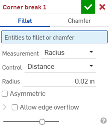
- 코너 분리 유형으로 필렛을 선택합니다.
- 그래픽 영역에서 금속 판재 모델의 코너 모서리 또는 꼭지점을 선택합니다. 코너 모서리 또는 꼭지점은 금속 판재 모델 및 평면도의 평면도 단면에서도 선택할 수 있습니다.
- 다음 중에서 측정 유형을 선택합니다.
- 반경 - 필렛의 반경 측정을 지정합니다.
- 폭 - 필렛에서 두 끝 사이의 거리를 지정합니다(일정 폭).
- 제어 유형을 선택합니다.
- 거리 - 필렛에는 반경 값이 입력된 둥근 모서리가 있습니다. Onshape는 새 필렛을 만들 때 이 값을 기억합니다.
- 원추형 - 필렛에 입력한 반지름 값과 선택적으로 필렛 스타일을 정의하기 위한 Rho 값을 가진 원추형 모서리가 있습니다.

Rho 값: 0.25(왼쪽, 타원형 곡선), 0.5(가운데, 포물선형 곡선), 0.999(오른쪽, 쌍곡선 - 확대)
- 곡률 - 필렛은 주변 모서리의 곡률을 사용자가 입력한 반지름 값과 일치시키고 선택적으로 0~.999 사이의 크기 값을 지정하여 탄젠트를 미세조정합니다. 제브라 스트라이프를 켜면 (분석 도구 표시 메뉴에서) 탄젠트를 더 명확하게 볼 수 있습니다.
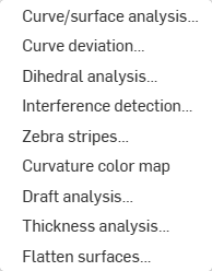
반지름 값을 입력할 경우, 아래 이미지에 화살표로 표시된 대로 매니퓰레이터 이동을 사용하여 필렛을 시각화하고 예상값에 근접할 수도 있습니다.
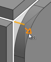
Onshape는 측정 유형 및 단면에 대한 선택 항목을 기억하고 이후 작업에서 마지막으로 선택한 옵션으로 대화상자를 엽니다.
- 비대칭을 선택하고, 필렛 모서리의 한쪽 끝에 서로 다른 필렛 모서리 반경 값을 지정하려면 두 번째 반경을 입력합니다. 비대칭 뒤집기 화살표를 클릭하여 필렛의 다른쪽 끝을 두 번째(비대칭) 필렛 모서리로 사용합니다.
- 기본적으로, 모서리 오버플로 허용은 비활성화되어 있습니다. 필요한 경우, 접선 모서리가 필렛 표면에서 '삭제'되도록 허용하려면 이를 선택합니다. 기본적으로 생성되는 모서리는 필렛 모서리를 따라 필렛의 방향을 엄격하게 제한합니다. 모서리 오버플로 허용을 활성화하면 필렛이 생성한 면의 모서리를 수정하여 매끄럽고 연속적인 표면을 만들 수 있습니다. 이 옵션을 선택하지 않으면 필렛 처리한 면의 모서리가 보존되어 파트가 더 자유롭게 움직일 수 있습니다.
모서리 오버플로 허용 드롭다운을 클릭하여 유지할 모서리를 선택할 수 있는 필드를 엽니다.
- 체크 표시(
 )를 클릭하여 새로운 코너 분리 피처를 적용합니다.
금속 판재 모형에 모따기된 코너 분리를 생성하기:
- 기존 금속 판재 모델이 있는 Part Studio에 있을 때, 코너 분리(
 )를 클릭합니다.
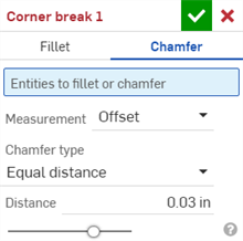
- 코너 분리 유형으로 모따기를 선택합니다.
- 그래픽 영역에서 금속 판재 모델의 코너 모서리 또는 꼭지점을 선택합니다. 코너 모서리 또는 꼭지점은 금속 판재 모델 및 평면도의 평면도 단면에서도 선택할 수 있습니다.
- 다음 중에서 측정 유형을 선택합니다.
- 오프셋 - 거리 필드에 입력한 시작 모서리부터 모따기까지의 거리를 설정합니다. 이 옵션은 모서리에 따라 달라집니다. 계산은 첫 번째 선택에서 시작하여 체인을 따라 진행됩니다.
- 탄젠트 - 거리 필드에 입력한 두 인접 면의 탄젠트 교차점에서 모따기까지의 거리를 설정합니다. 이 옵션은 모서리에 종속되지 않습니다.
- 모따기 유형 선택:
- 동일 거리 - 모따기가 모서리로부터 양방향으로 동일한 거리만큼 연장됩니다.
- 두 거리 - 모따기가 각 방향으로 서로 다른 거리만큼 연장됩니다.
- 거리 및 각도 - 모따기는 지정한 거리를 한 방향으로는 연장하고 다른 방향으로는 지정된 각도만큼 연장합니다.
Onshape는 면 유형에 대한 선택 항목을 기억하고 이후 작업에서 마지막으로 선택한 옵션으로 대화상자를 엽니다.
- 모따기 거리를 입력합니다. Onshape의 각도 기본값은 45도로 설정되어 있지만 동일 거리와 거리 및 각도 모따기에 대해 마지막으로 입력한 거리 값을 기억합니다.
- 두 거리 또는 거리 및 각도를 선택한 경우, 화살표 버튼을 클릭하여 모든 모서리의 방향을 반전하거나 방향 재정의 필드에서 반전할 개별 모서리를 지정합니다.
- 체크 표시(
 )를 클릭하여 새로운 코너 분리 피처를 적용합니다.
-
코너 분리 피처가 적용된 후에는 모든 모델 조인트의 유형(립 또는 벤드) 및 스타일(모서리 이음 또는 맞대기 이음)을 더 이상 금속 판재 테이블 및 플랫 뷰에서 편집할 수 없습니다. 금속 판재 모형의 플랜지와 조인트에 대한 모든 편집을 완료한 후 코너 분리 피처를 추가하는 것이 좋습니다.
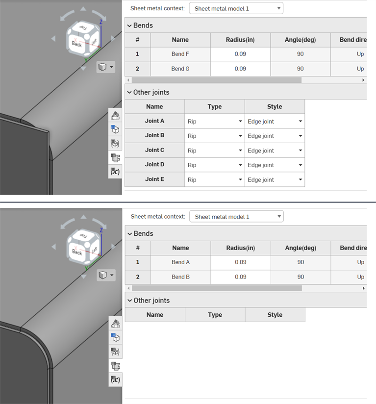
코너 분리 기능 적용 전(위), 코너 분리 기능 적용 후(아래)
-
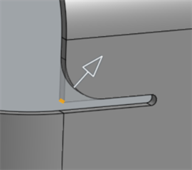
코너 분리를 사용하여 코너 외에도 굽힘 릴리프 모서리와 꼭지점에 필렛이나 모따기를 적용할 수 있습니다.
-
단일 코너 분리 피처를 사용하여 코너에 여러 필렛, 모따기 또는 이 둘의 조합을 추가할 수 없습니다. 추가 코너 분리 피처를 생성하여 기존 코너 분리 피처의 꼭지점 또는 모서리에 필렛이나 모따기를 추가합니다.
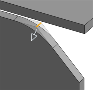
두 번째 코너 분리 피처를 사용하여 모따기 모서리에 필렛 적용
금속 판재 모델이 활성화된 경우(생성 또는 편집 중), 추가 도구를 사용할 수 있습니다.
-
 플랜지 - 선택한 각 모서리에 대해 벽을 생성하고 선택한 모서리에 굽힘으로 연결합니다.
 -
 둘러싸기 - 기존의 금속 판재 파트에서 선택한 각 모서리/면에 대해 둘러싸기를 생성합니다.
 -
 탭 - 금속 판재 플랜지에 탭을 추가합니다.
 -
 굽힘 - 추가 굽힘 제어 옵션을 사용하여 참조선을 따라 금속 판재 모델을 굽힙니다.
 -
 양식 - 기존 금속 판재 모델에 양식 피처를 생성합니다. 현재 통합문서, 다른 통합문서 또는 미리 정의된 금속 판재 양식 라이브러리에서 양식을 선택할 수 있습니다.
 -
 Loft - Create sheet metal models that connect two profiles.
 -
 조인트 만들기 - 두 벽의 교차점을 굽힘(원통형 형상으로 결합된 벽) 또는 립(두 벽 사이의 작은 간격)과 같은 조인트 피처로 변환합니다.
 -
 코너 - 코너 유형과 릴리프 스케일을 수정합니다.
 -
 굽힘 릴리프 - 굽힘 릴리프(굽힘 끝이 자유 모서리와 만나는 작은 컷), 깊이 및 릴리프 너비를 수정합니다.
 -
 조인트 수정 - 굽힘을 립으로 변환하는 등 기존의 조인트에 대한 변경을 수행합니다. 현재 플랫 뷰 테이블을 통해 사용할 수 있습니다.
 -
 코너 분리 - 필렛이나 모따기를 적용하여 기존 금속 판재 파트의 코너를 끊습니다. 코너 모서리 또는 꼭지점을 선택하고 코너 분리 유형과 거리를 지정합니다. 금속 판재 모델의 모든 플랜지와 조인트를 완성한 후에 이 피처를 사용하는 것이 좋습니다.
 -
 금속 판재 테이블 및 플랫 뷰 - 금속 판재 모델 플랫 패턴의 립/굽힘 테이블 및 시각화를 열고 닫습니다. 이 테이블을 사용하여 립을 굽힘으로 변환하거나 반대로 변환할 수 있습니다.
 -
 금속 판재 모델 마감 - 금속 판재 모델을 닫거나 비활성화하고 피처 리스트에 피처를 생성합니다.
금속 판재 모형에 필렛 처리된 코너 분리 생성하기:
- 기존 금속 판재 모델이 있는 Part Studio에 있을 때, 코너 분리(
 )를 탭합니다.
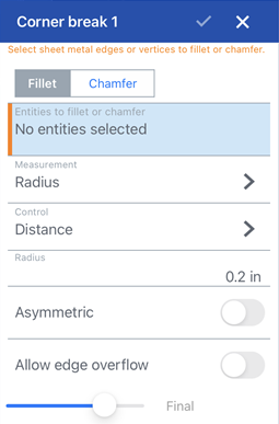
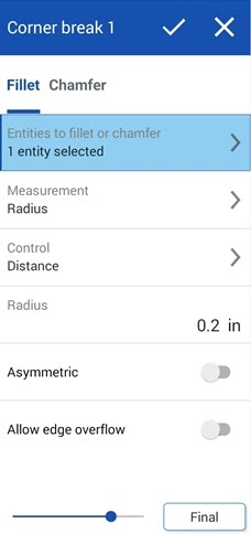
코너 분리: iOS용 필렛 대화상자(위 첫 번째 이미지) 및 Android용 필렛 대화상자(위 두 번째 이미지)
- 필렛을 탭하여 코너 분리 유형을 선택합니다.
- 그래픽 영역에서 금속 판재 모형의 모서리 또는 꼭지점을 선택합니다.
- 다음 중에서 측정 유형을 선택합니다.
- 반경 - 필렛의 반경 측정을 지정합니다.
- 폭 - 필렛에서 두 끝 사이의 거리를 지정합니다(일정 폭).
- 제어 유형을 선택합니다.
- 거리 - 필렛에는 반경 값이 입력된 둥근 모서리가 있습니다. Onshape는 새 필렛을 만들 때 이 값을 기억합니다.
- 원추형 - 필렛에 입력한 반지름 값과 선택적으로 필렛 스타일을 정의하기 위한 Rho 값을 가진 원추형 모서리가 있습니다.

Rho values: 0.25 (left; elliptical curve); 0.5 (middle; parabolic curve); 0.999 (right; hyperbolic curve - zoomed in)
- 곡률 - 필렛은 주변 모서리의 곡률을 사용자가 입력한 반경 값과 일치시키고 선택적으로 0~.999 사이의 크기 값을 일치시켜 탄젠트를 조정합니다.
반지름 값을 입력할 경우, 아래 이미지에 화살표로 표시된 대로 매니퓰레이터 이동을 사용하여 필렛을 시각화하고 예상값에 근접할 수도 있습니다.
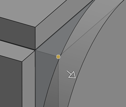
- 비대칭을 켜고, 필렛 모서리의 한쪽 끝에 서로 다른 필렛 모서리 반경 값을 지정하려면 두 번째 반경을 입력합니다. 비대칭 뒤집기 화살표를 클릭하여 필렛의 다른쪽 끝을 두 번째(비대칭) 필렛 모서리로 사용합니다.
- 기본적으로, 모서리 오버플로 허용은 꺼져 있습니다. 이 옵션을 켜면 필요한 경우 접선 모서리가 필렛 표면에서 '삭제'될 수 있습니다. 기본적으로 생성되는 모서리는 필렛 모서리를 따라 필렛의 방향을 엄격하게 제한합니다. 모서리 오버플로 허용을 활성화하면 필렛이 생성한 면의 모서리를 수정하여 매끄럽고 연속적인 표면을 만들 수 있습니다.이 옵션을 끄면 필렛된 면의 모서리가 보존되어 파트가 더 자유롭게 움직일 수 있습니다.
유지할 모서리 필드를 탭하고 그래픽 영역에서 유지할 모서리를 선택합니다.
- 체크 표시를 탭하여 새로운 코너 분리 피처를 적용합니다.
금속 판재 모형에 모따기된 코너 분리를 생성하기:
- 기존 금속 판재 모델이 있는 Part Studio에 있을 때, 코너 분리(
 )를 탭합니다.
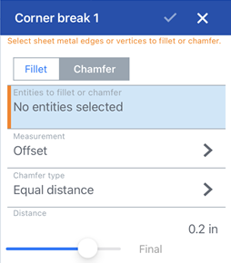
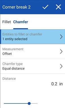
코너 분리: iOS용 모따기 대화상자(위 첫 번째 이미지) 및 Android용 모따기 대화상자(위 두 번째 이미지)
- 코너 분리 유형으로 모따기를 탭합니다.
- 그래픽 영역에서 금속 판재 모형의 모서리 또는 꼭지점을 선택합니다.
- 다음 중에서 측정 유형을 선택합니다.
- 오프셋 - 거리 필드에 입력한 시작 모서리부터 모따기까지의 거리를 설정합니다. 이 옵션은 모서리에 따라 달라집니다. 계산은 첫 번째 선택에서 시작하여 체인을 따라 진행됩니다.
- 탄젠트 - 거리 필드에 입력한 두 인접 면의 탄젠트 교차점에서 모따기까지의 거리를 설정합니다. 이 옵션은 모서리에 종속되지 않습니다.
- 모따기 유형 선택:
- 동일 거리 - 모따기가 모서리로부터 양방향으로 동일한 거리만큼 연장됩니다.
- 두 거리 - 모따기가 각 방향으로 서로 다른 거리만큼 연장됩니다.
- 거리 및 각도 - 모따기는 지정한 거리를 한 방향으로는 연장하고 다른 방향으로는 지정된 각도만큼 연장합니다.
- 모따기 거리를 입력합니다. Onshape의 각도 기본값은 45도로 설정되어 있지만 동일 거리와 거리 및 각도 모따기에 대해 마지막으로 입력한 거리 값을 기억합니다.
- 두 거리 또는 거리 및 각도를 선택한 경우, 화살표 버튼을 탭하여 모든 모서리의 방향을 반전하거나 방향 재정의 필드에서 반전할 개별 모서리를 지정합니다.
- 체크 표시를 탭하여 새로운 코너 분리 피처를 적용합니다.
-
코너 분리 피처가 적용된 후에는 모든 모델 조인트의 유형(립 또는 벤드) 및 스타일(모서리 이음 또는 맞대기 이음)을 더 이상 금속 판재 테이블 및 플랫 뷰에서 편집할 수 없습니다. 금속 판재 모형의 플랜지와 조인트에 대한 모든 편집을 완료한 후 코너 분리 피처를 추가하는 것이 좋습니다.
-
코너 분리를 사용하여 코너 외에도 굽힘 릴리프 모서리와 꼭지점에 필렛이나 모따기를 적용할 수 있습니다.

-
단일 코너 분리 피처를 사용하여 코너에 여러 필렛, 모따기 또는 이 둘의 조합을 추가할 수 없습니다. 추가 코너 분리 피처를 생성하여 기존 코너 분리 피처의 꼭지점 또는 모서리에 필렛이나 모따기를 추가합니다.

두 번째 코너 분리 피처를 사용하여 모따기 모서리에 필렛 적용
금속 판재 모델이 활성화된 경우(생성 또는 편집 중), 추가 도구를 사용할 수 있습니다.
-
 플랜지 - 선택한 각 모서리에 대해 벽을 생성하고 선택한 모서리에 굽힘으로 연결합니다.
 -
 탭 - 금속 판재 플랜지에 탭을 추가합니다.
 -
 조인트 만들기 - 두 벽의 교차점을 굽힘(원통형 형상으로 결합된 벽) 또는 립(두 벽 사이의 작은 간격)과 같은 조인트 피처로 변환합니다.
 -
 코너 - 코너 유형과 릴리프 스케일을 수정합니다.
 -
 굽힘 릴리프 - 굽힘 릴리프(굽힘 끝이 자유 모서리와 만나는 작은 컷), 깊이 및 릴리프 너비를 수정합니다.
 -
 Loft - View and modify sheet metal models that connect two profiles.
 -
 코너 분리 - 필렛이나 모따기를 적용하여 기존 금속 판재 파트의 코너를 끊습니다. 코너 모서리 또는 꼭지점을 선택하고 코너 분리 유형과 거리를 지정합니다. 금속 판재 모델의 모든 플랜지와 조인트를 완성한 후에 이 피처를 사용하는 것이 좋습니다.
 -
 금속 판재 모델 마감 - 금속 판재 모델을 닫거나 비활성화하고 피처 리스트에 피처를 생성합니다.