 치수
치수
![]()
![]()
![]()
이용 가능 플랫폼: 스케치
단축키: d
수평, 수직, 최단 거리, 각도, 지름, 호 길이 또는 반지름 치수를 스케치 형상에 추가하거나 스케치 형상 및 면 사이에 추가합니다. 치수를 구동(기준) 또는 고정 구동으로 지정할 수 있습니다.
측정 도구를 사용하여 그래픽 영역 안에 있는 무엇이든지 측정할 수 있습니다.
일부 도구를 이용하면 스케치할 때 치수를 지정할 수 있습니다.
또한 스케치의 컨텍스트 메뉴(RMB)에서 치수 표시 명령을 사용하여 기존의 치수를 확인할 수 있습니다.
치수는 스케치 요소를 정의하는 강력한 방법입니다. 스케치에 치수를 추가하는 방법에는 두 가지가 있습니다. 첫 번째 방법은 스케치를 작성할 때 치수를 추가하는 것이고, 두 번째 방법은 먼저 스케치 형상을 생성한 다음, 치수를 추가하는 것입니다.
스케치하는 동안 치수를 추가하려면 형상을 스케치한 후 숫자를 입력하고 Enter 키를 누릅니다. 예를 들어, 선을 배치합니다. 두 번째 끝점을 선택하면 선 길이가 표시된 흰색 상자가 나타납니다. 값을 입력하고 Enter 키를 눌러 치수를 지정합니다. 이 방법은 거의 모든 스케치 도구에 적용됩니다.
직사각형과 같이 두 개의 치수를 포함하는 형상을 정의할 때는 먼저 수평 치수를 입력한 다음 Enter 키를 누릅니다. 입력은 자동으로 수직 치수로 전환됩니다.
치수를 추가하는 두 번째 방법은 스케치 형상이 완료된 후에 치수를 추가하는 것입니다. 치수 도구를 선택하거나 단축키 D를 사용합니다. 치수를 적용할 요소를 마우스 왼쪽 버튼으로 클릭합니다. 커서를 이동하고 마우스 왼쪽 버튼을 클릭하여 치수를 배치합니다. 치수 값을 입력하고 Enter 키를 누릅니다. 배치된 첫 번째 치수와 일치하도록 스케치의 크기가 자동으로 조정됩니다.
Onshape의 스케치 치수는 선택한 요소 유형에 직관적으로 반응합니다. 이렇게 하면 호나 원의 외부 또는 내부에 대한 치수 측정이 원활해집니다. 호나 원의 외부 가까이를 마우스 왼쪽 버튼으로 클릭하여 외부 치수를 지정합니다. 내부에 치수를 지정하려면 호 또는 원의 내부 가까이에서 마우스 왼쪽 버튼을 클릭합니다. 동일한 직관적인 주제에 따라 치수 도구는 평행하지 않은 두 선의 치수를 측정할 때 자동으로 각도 치수를 배치합니다.
치수를 편집하려면 그래픽에서 치수를 두 번 클릭합니다. 새 값을 입력하고 Enter를 눌러 적용합니다. 그래픽 영역에서 치수를 선택하여 치수를 삭제하고 키보드에서 삭제를 누릅니다. 차원을 사용하여 다른 차원 및 관계에 의해 결정되는 값을 표시할 수도 있습니다. 구동 치수는 스케치에서 회색으로 표시되는 반면 구동 치수는 검은색으로 표시됩니다. Onshape는 배치가 스케치를 과도하게 정의하는 경우 자동으로 새 치수를 구동 치수로 전환합니다. 마우스 오른쪽 버튼 클릭 메뉴에서 치수의 구동 상태를 수동으로 전환합니다.
-
 을 클릭하거나 d 키를 누릅니다.
 - 치수를 지정할 요소(또는 그 사이의 요소)와 치수의 위치를 선택합니다.
선택한 요소가 강조 표시되고(브라우저에서만), 치수를 배치한 곳에 치수 컨텍스트 대화상자가 열립니다. 자세한 내용은 치수 컨텍스트 대화상자를 참조하십시오.
- 값을 입력하고 Enter 키를 눌러 값을 적용합니다. 차원에 변수를 사용할 수도 있습니다. =#d에서와 같이 "=#"과 변수 이름을 입력하기만 하면 됩니다.
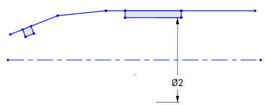
치수(길이, 선형 거리 및 각도)에 음수 값을 입력하여 요소의 방향을 반전시킬 수 있습니다.
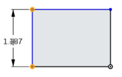
아래 이미지는 양의 치수를 나타냅니다. 하단 수평선을 기준으로 사각형의 위치를 확인하십시오.
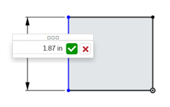
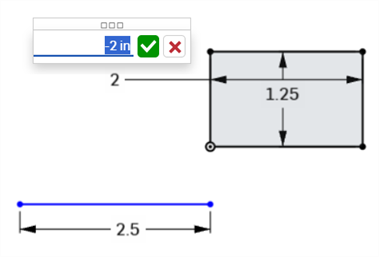
다음 이미지는 활성 필드에 입력되는 음의 치수 값을 보여줍니다.
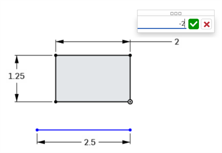
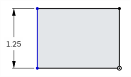
값이 승인되면 직사각형의 방향이 바뀝니다.
-
Part Studio의 숫자 필드에 식 및 삼각함수를 사용할 수 있습니다.
-
치수를 선택하고 삭제 키를 눌러 삭제하거나, 치수를 선택하고 컨텍스트 메뉴에서 삭제를 선택합니다.
-
해당 위치의 치수를 편집하려면, 값을 두 번 클릭하여 필드를 활성화한 다음, 새 값을 입력하십시오. 변경 내용을 수락하려면 Enter를 누르십시오.
-
To add a comment to a dimension, right-click the dimension and select Add comment from the context menu. See Comments.
-
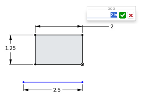
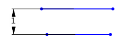
지름 및 반경 치수를 제외하고, 새 치수 값을 입력하면 치수가 기입되는 두 형상 선택이 모두 새 입력 값의 절반만큼 변환되므로 두 형상 선택이 동일하게 변환됩니다. 예를 들어, 단일 선에 치수를 기입할 때 각 끝점은 치수 값의 절반만큼 변환되므로 두 끝점이 동일하게 변환됩니다.
-
구속된 형상은 변환되지 않을 수 있습니다. 구속 조건 사용하기를 참조하십시오.
- 치수 도구(
 )를 클릭합니다.
 - 첫 번째 줄을 클릭합니다.
- 두 번째 줄을 클릭합니다.
- 드래그하여 선형 거리 치수를 배치합니다.
- 클릭하여 동시에 치수를 배치하고 해당 수치값 필드를 엽니다.
-
선택적으로, 새 치수 값을 입력할 수도 있습니다.
-
Enter 키를 눌러 치수 값을 승인합니다.
두 선 사이의 치수를 기입할 때 이는 시각적 평행 구속 조건이 없는 병렬화를 의미합니다.
- 치수 도구()를 클릭합니다.
- 첫 번째 코너 점을 클릭합니다.
- 첫 번째 꼭지점과 대각선으로 두 번째 꼭지점을 클릭합니다.
- 각도로 드래그하여 대각선 거리 치수를 배치합니다.
- 클릭하여 동시에 치수를 배치하고 해당 수치값 필드를 엽니다.
-
선택적으로, 새 치수 값을 입력할 수도 있습니다.
-
Enter 키를 눌러 치수 값을 승인합니다.
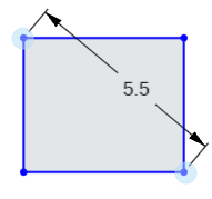
이 치수는 두 점 사이의 최단 거리의 치수를 지정합니다.
- 치수 도구()를 클릭합니다.
- 첫 번째 선의 끝점을 클릭합니다.
- 두 번째 선의 끝점을 클릭합니다.
- 일정 각도로 드래그하여 직접 거리 치수를 배치합니다.
- 클릭하여 동시에 치수를 배치하고 해당 수치값 필드를 엽니다.
-
선택적으로, 새 치수 값을 입력할 수도 있습니다.
-
Enter 키를 눌러 치수 값을 승인합니다.
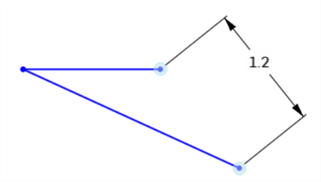
이 치수는 두 점 사이의 선형 거리를 측정합니다.
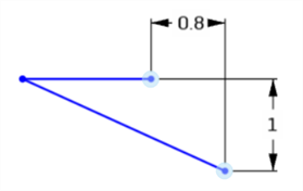
- 치수 도구()를 클릭합니다.
- 첫 번째 선의 끝점을 클릭합니다.
- 두 번째 선의 끝점을 클릭합니다.
- 직선 위/아래 또는 왼쪽/오른쪽으로 드래그하여 선형 거리 치수를 배치합니다.
- 클릭하여 동시에 치수를 배치하고 해당 수치값 필드를 엽니다.
-
선택적으로, 새 치수 값을 입력할 수도 있습니다.
-
Enter 키를 눌러 치수 값을 승인합니다.
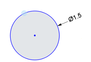
- 치수 도구()를 클릭합니다.
- 원의 모서리를 클릭합니다.
- 원 안쪽이나 바깥쪽으로 드래그하여 지름 치수를 배치합니다.
- 클릭하여 동시에 치수를 배치하고 해당 수치값 필드를 엽니다.
-
선택적으로, 새 치수 값을 입력할 수도 있습니다.
-
Enter 키를 눌러 치수 값을 승인합니다.
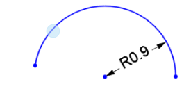
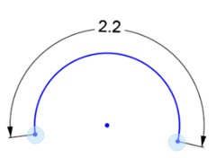
- 치수 도구()를 클릭합니다.
- 호를 클릭합니다.
- 호 안쪽이나 원호 바깥쪽으로 드래그하여 반경 치수를 배치합니다.
- 클릭하여 동시에 치수를 배치하고 해당 수치값 필드를 엽니다.
-
선택적으로, 새 치수 값을 입력할 수도 있습니다.
-
Enter 키를 눌러 치수 값을 승인합니다.
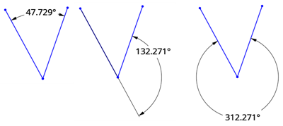
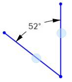
- 치수 도구()를 클릭합니다.
- 첫 번째 줄을 클릭합니다.
- 첫 번째 선과 각도로 두 번째 선을 클릭합니다.
- 각도의 안쪽이나 바깥쪽으로 드래그하여 각도 치수를 배치합니다.
각도를 정의하려는 사분면으로 치수를 드래그할 수도 있습니다.
- 클릭하여 동시에 치수를 배치하고 해당 수치값 필드를 엽니다.
-
선택적으로, 새 치수 값을 입력할 수도 있습니다.
-
Enter 키를 눌러 치수 값을 승인합니다.
- 치수 도구()를 클릭합니다.
-
호의 첫 번째 끝점을 클릭합니다.
-
호의 두 번째 끝점을 클릭합니다.
-
호를 클릭합니다.
-
드래그하여 호 길이 치수를 배치합니다.
-
클릭하여 동시에 치수를 배치하고 해당 수치값 필드를 엽니다.
-
선택적으로, 새 치수 값을 입력할 수도 있습니다.
-
치수 값을 승인하려면 Enter 키를 누릅니다.
스플라인이나 스플라인 점의 두 점과 다른 스케치 점 사이의 거리에 치수를 기입합니다.
-
치수 도구(
)를 클릭합니다. -
첫 번째 스플라인 점을 클릭합니다.
-
두 번째 스플라인 점(또는 다른 스케치 점)을 클릭합니다.
-
드래그하여 거리 치수를 배치합니다.
-
클릭하여 동시에 치수를 배치하고 해당 수치값 필드를 엽니다.
-
선택적으로, 새 치수 값을 입력할 수도 있습니다.
-
치수 값을 승인하려면 Enter 키를 누릅니다.
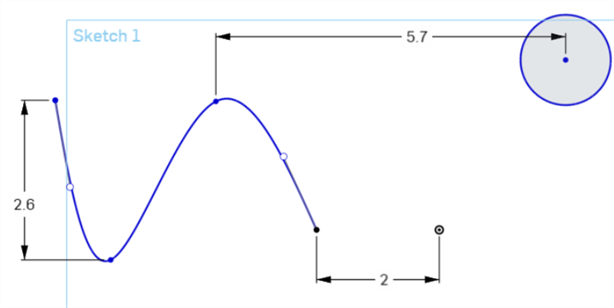
또한 커서를 일정 각도로 드래그하여 직접 거리 치수를 배치하면 스플라인이나 스플라인 점의 두 점과 다른 스케치 점 사이의 직접 거리를 확인할 수 있습니다. 직선 거리를 참조하십시오.
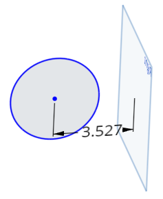
이 치수는 평면과 다른 스케치 점 사이의 거리를 측정합니다.
-
치수 도구(
)를 클릭합니다. -
스케치 점을 클릭합니다.
-
면을 클릭합니다.
-
드래그하여 거리 치수를 배치합니다.
-
클릭하여 동시에 치수를 배치하고 해당 수치값 필드를 엽니다.
-
선택적으로, 새 치수 값을 입력할 수도 있습니다.
새 치수 값을 입력하면 평면이 제자리에 있는 동안 스케치 형상이 이동합니다.
-
치수 값을 승인하려면 Enter 키를 누릅니다.
원, 점 또는 비보조선과 보조선 사이에 중심선 치수를 생성합니다(예: 회전 작업을 위해 파트의 치수를 잴 경우). 이들 스케치 요소 중 하나 간에 거리 치수를 시작한 다음, 마우스를 보조선의 반대쪽으로 이동합니다. 보조선을 가로질러 마우스를 움직이면 거리와 중심선 치수 간에 상태가 전환됩니다.
-
치수 도구(
)를 클릭합니다. -
원 또는 스케치 점을 클릭합니다.
-
보조선을 클릭합니다. 그 결과 두 선 사이의 거리 치수가 생성됩니다.
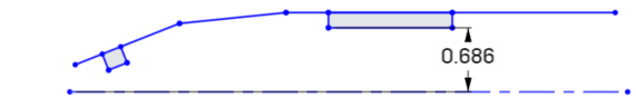
- 상태를 중심선 치수로 전환하는 동시에 중심선 치수의 위치를 지정하려면 보조선의 반대쪽으로 끕니다.
- 클릭하여 동시에 치수를 배치하고 해당 수치값 필드를 엽니다.
-
선택적으로, 새 치수 값을 입력할 수도 있습니다.
-
Enter 키를 눌러 치수 값을 승인합니다.
구동 치수는 여유 값 또는 벽 두께를 특정 값 이상으로 유지하는 것과 같이 디자인 의도를 유지하는 데 유용합니다.
- Dimensions are driving by default. Right-click on a dimension value to select Change to driving/driven dimension from the context menu:
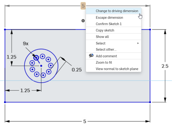
- 고정 구동 치수는 검정색으로 나타나고 편집할 수 있습니다.
- 구동 치수는 옅은 회색으로 나타나고 편집할 수 없습니다(필요하면 '고정 구동'으로 전환한 다음 편집합니다).
- 스케치에 추가된 치수가 스케치를 초과 정의할 경우, 해당 치수가 자동으로 '구동'으로 설정됩니다.
- 고정 구동 치수를 추가할 수 있는 곳이면 어디든지 구동 치수를 추가할 수 있습니다.
- 구동 치수는 내포된 치수의 값을 반영하며, 형상을 변경하지 않습니다.
- 치수가 구동에서 고정 구동으로 전환되면 형상이 변경됩니다. 구동 치수에서 고정 구동으로 변경으로 인해 스케치가 과도하게 구속될 경우, 보통 때와 같이 빨간색 표시기가 나타납니다.
Onshape에서는 사용자가 일부 치수에 대해 음수 값을 입력할 수 있습니다. 음수 값을 수락하는 치수에 대해서는 아래를 참조하십시오.
Onshape는 다음에 대해 음수 값을 허용합니다.
- 거리 치수
- 각도 치수
- 선 길이
- 스플라인 치수
Onshape는 다음에 대해 음수 값을 허용하지 않습니다.
- 호 치수
- 반지름 또는 지름 치수