合致
![]()
![]()
![]()
Onshape における合致は、旧 CAD システムの合致とは異なります。2 つのインスタンス間の移動 (自由度) は合致に埋め込まれるため、多くのアセンブリでは任意の 2 つのインスタンス間に必要な Onshape の合致は 1 つのみです。合致には独自の座標系が含まれているため、2 つのエンティティ間の自由度を定義するために 1 つの合致のみ使用します。2 つのエンティティ間に合致を配置するときに、Onshape は、合致の座標系と整列する各エンティティ上の点を提供します。提案された位置は、パーツの基本ジオメトリに基づいており、ジオメトリを変更すると、合致の位置が変わります。これは特定の状況では望ましくない場合がありますが、次のことも可能です。
- 合致の作成中にジオメトリが暗黙的合致コネクタをまだ許可していない場合は、エンティティに明示的な合致コネクタを必要な場所に追加します。詳細は、合致コネクタを参照してください。
- 合致コネクタの位置合わせに使用するアセンブリにレイアウトまたは参照スケッチを挿入します。
- 必要に応じて複数の合致を使用してください。
ショートカット: m
アセンブリ内の合致の表示/非表示を切り替えるには、ショートカットキー j を使用します。
アセンブリでは、エンティティを原点に合致できます。コンテキストメニューまたはドラッグを使用して、割り当てられた合致の動きをテストするために、エンティティを固定することもできます。
エンティティには、パーツ、アセンブリ、サブアセンブリ、スケッチ、およびサーフェスが含まれます。
Onshape の合致には、合致コネクタと合致という 2 つの側面があります。Onshape では、インスタンスジオメトリを直接合致する代わりに、合致コネクタを使用します。合致コネクタは、エンティティ上またはエンティティ間にあるローカル座標系です。これらは合致フィーチャーでインスタンスを見つけて相互を向き合わせるために使用され、合致ダイアログの外で明示的に作成されるか、合致の作成中に暗黙的に作成されます。
新しい合致フィーチャーを開始します。合致タイプはこのダイアログで編集でき、合致をすばやく変更できます。Onshape は、インスタンスが意図した動作に基づいて合致を定義します。それぞれが特定の自由度を制限しますが、[固定] は 6 つすべてを制限します。
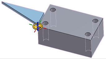
合致フィーチャーが有効な場合は、面やエッジにカーソルを合わせると、合致コネクタを配置できる可能性のある位置を示す暗黙的な合致コネクタ点が表示されます。これらの点は、面またはスケッチ輪郭の重心、中点、頂点、円形の開口部の中心、切断用の負のスペースの中心、円錐面の仮想交点に表示されます。
Shift キーを押したままにすると、カーソルを移動しても現在の参照面またはエッジがロックされます。これにより、狭い場所や負のスペースにある場合でも、点を簡単に選択できます。カーソルをジオメトリ上に移動すると、合致コネクタは最も近い点にスナップします。
この例では最初に、穴の中心にある合致コネクタ点を選択します。この面は、もう一方のインスタンスの円形の面と接触させて軸を揃える必要があります。円形の面とエッジは、中点や頂点がなく、重心しかないため、合致コネクタの点を選択する最も迅速な方法です。この合致では、2 つ目のインスタンスの円形エッジを 2 番目に選択します。このインスタンスは最初のインスタンスと接触させて軸を揃える必要があります。選択した 2 つのインスタンスは一緒に移動し、合致コネクタの主 Z 軸が揃った状態で配置されます。
主軸の方向を逆にするには、矢印アイコンをクリックします。二次軸を 90 度ずつ回転させるには、[二次軸の向きを変更] アイコンをクリックします。フィールドの一番上の合致コネクタは、何が反転し、何が回転しているかを示します。動きが制限される場合は、代わりにフィールドの下部の合致コネクタが反転または回転します。もう一方の合致コネクタの変更するには、[アイテムの並べ替え] をクリックし、右側のハンドルを使って並べ替えます。[完了] をクリックして並べ替えを完了します。二次軸の向きを変えると、もう一方の合致コネクタが回転します。
各合致フィーチャーは、合致コネクタ間の自由度を定義します。合致の動きを視覚化するには、[合致の自由度をアニメート] アイコンを使います。ファスナー合致の自由度はゼロなので、合致コネクタ間は動きません。合致タイプをスライダに変更すると、アニメーションによってインスタンスが主 Z 軸に沿って移動します。
合致フィーチャーは、制限のオフセットと適用に対応しています。オフセットを使用して、設定した値で軸に沿ってインスタンスを移動または回転させます。制限を使用して合致の動きの範囲を制限します。使用可能な制限は、合致の自由度に基づいています。
合致フィーチャーを定義している間、Onshape は合致フィーチャーが確定されるまで、すべての合致とその位置を継続的に計算しません。[解決] を使用してすべての合致フィーチャーを計算し、インスタンスの位置を更新してください。
[合致フィーチャー] では、定義された合致が時系列で一覧表示されます。制限のある合致には制限アイコンが表示されます。合致の上にカーソルを置くと、合致のオフセットと制限の定義が表示されます。合致を右クリックすると、そのコンテキストメニューが表示されます。コンテキストメニューから合致を編集するか、合致をダブルクリックして編集します。位置に制限を適用して、定義された制限に基づいて全範囲の動きを確認します。[リセット] は合致を元の位置に戻し、[削除] はアセンブリから合致を削除します。
合致は、合致ダイアログで定義されます。
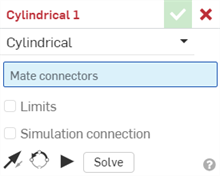
作成する合致のタイプを選択し、合致コネクタ (パーツごとに 1 つ) を選択します。また、このチェックボックスをオンにして、移動の制限を適用することもできます。その他のオプション/アクションは次のとおりです。
-
 - インスタンスの主軸、Z 方向を反転します。
 -
 - 二次軸の方向を変更します。クリックすると、インスタンスの象限方向 (XY 平面内) を 90 度回転します。
 -
 - アセンブリで他のすべての合致を無視して、合致における無制限の移動のアニメーションをプレビューします。
 - 解決する - これを含むすべてのアセンブリ合致を解決します。
多くの合致では、合致するパーツ間の固定スペースを定義するオフセット距離を設定できるほか、移動の距離 制限 を設定する機能を提供します。
境界は、端点にバーがある破線でグラフィック領域に表示されます。破線は移動の方向と距離を表し、実線は限界を表します。
合致に 1 つまたは複数の制限が適用されている場合、合致フィーチャーリストの合致の右側に合致制限のインジケータアイコン ![]() が表示されます。
が表示されます。
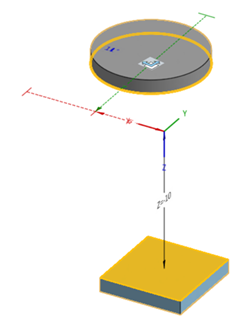
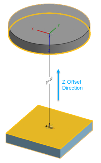
オフセット距離は、合致間の破線でグラフィック領域に可視化され、値と軸が表示されます。ダイアログに距離を入力します。
合致をクリックすると、グラフィックが表示され、合致によって定義された X、Y、Z の方向と、オフセットおよび寸法の制限の範囲 (存在する場合) が示されます。
オフセットを適用した場合、座標系全体を移動することで表示されます。オフセットは、最初に選択した合致コネクタを基準にします。
[オフセット] ボックスをオンにすると、多くの合致で、特定の軸を中心とした回転を指定するオプションも使用できます。スライダ、回転、ピンスロット、平面、ファスナーの各合致には、以下のようにこのオプションがあります。
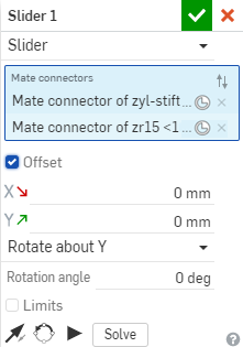
回転の中心となる軸を上から選択し、回転角度を入力します。
合致ダイアログボックスを開き、2 つの合致コネクタを選択すると、カーソル位置にヘッドアップディスプレイが表示されます。

ヘッドアップディスプレイのチェックマークをクリックして、現在の合致を確定し、新しい合致を開始します。合致ダイアログボックスは開いたままなので、引き続き合致を選択できます。
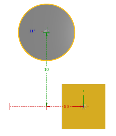
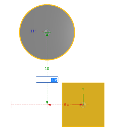
オフセット距離は、編集可能な値で、合致間の破線でグラフィック領域に表示されます。パーツを目的の位置までドラッグし、距離の値をダブルクリックして新しい値を入力します。これらの値は保持されません。ダイアログの [オフセット] フィールドに入力する値を推定したり、パーツを正確な位置に配置して測定することができます。例:
軸と回転運動の合致値 (上述)。
編集中の合致値 (上述)。
[合致] のコンテキストメニューを使用して、次のコマンドにアクセスします。
- 名前を変更 - 合致に別の名前を指定します
- 編集... - 合致の定義を変更します (合致が抑制されている場合も)
- 制限位置を適用 - 合致に制限を作成すると、インスタンスを最小または最大の制限値に自動的に移動します。
- リセット - アセンブリをドラッグして合致の移動をテストした後、[リセット] を使用してアセンブリを開始位置またはホーム位置に戻します (拘束が制限されないと仮定)
- アニメーション化 - 単一の合致 (または合致内の単一の DOF) からアセンブリを操作します。
- 非表示 - ビューから削除 ([表示] に再び合致が表示されます)
- すべての合致を表示 - すべての合致コネクタを表示
- 分離 - 選択したもの (または選択した合致に関連付けられているもの) 以外のすべてのパーツの表示を暗くして非アクティブにします。分離モードの場合、このメニューの上部に [分離を終了] が表示されます。詳細は、アセンブリの管理を参照してください。
- 透明にする - 選択した合致に最も近いパーツを薄く表示します。[透明にする] ダイアログのスライダを使用して、選択した合致との距離または接続によって、透明度を他のパーツに拡張します。
- 抑制 - 合致のない (および合致 を削除しない) アセンブリを可視化します。合致および合致コネクタは、関連付けられているパーツまたはアセンブリが抑制されると、自動的にアクティブでなくなります (抑制された合致は編集可能です)。
- 選択を解除 - すべての選択を取り消します。
- 削除 - アセンブリから合致を削除します。
2 つの明示的合致コネクタまたは暗黙的合致コネクタの間に合致を作成すると、どちらの合致コネクタも編集できます。
-
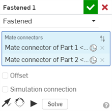
合致ダイアログを開きます。以下の例では、ファスナー合致を例として使用しています。このプロセスは、合致コネクタを使用しない接線合致を除き、すべての合致で同様です。
-
合致コネクタアイコン (
 ) をクリックします。合致コネクタダイアログが開き、合致コネクタの原点タイプ、原点エンティティ、配置、位置、主軸方向、二次軸方向を編集できます。
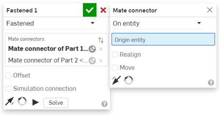
合致ダイアログからの合致コネクタの編集は、現在のアセンブリにある暗黙的コネクタまたは明示的コネクタに限定されます。Part Studios、サブアセンブリ、またはリンクされたドキュメントの合致コネクタは、元の場所で編集する必要があります。
詳細は、合致コネクタを参照してください。
合致が作成され、[合致フィーチャー] リストに表示されたら、合致を選択 (または Ctrl を押しながらクリックして複数を選択) し、ドラッグアンドドロップしてリスト内の順序を並べ替えます。これにより、最も重要な合致フィーチャーをリストに表示しやすくなります。Onshape は合致を同時に解決するため、順序は合致に影響しません。
[球]、[固定]、[接線]、[幅] を除くすべての合致の [合致] の値を指定できます。Onshape には、距離の視覚的なキューがあり、2 番目に選択した合致コネクタから最初の合致コネクタまでの距離値が既定の単位で表示されます。正の値と負の値で制限を指定します。
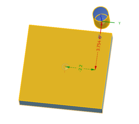
この例では、ボックス上の合致コネクタはダイアログで最初に選択され、円柱の合致コネクタは 2 番目に選択されています。Y 値が負で、X の値が正であることに注意してください。
ここで、合致コネクタの選択順序を切り替えて、距離の値に注意します。
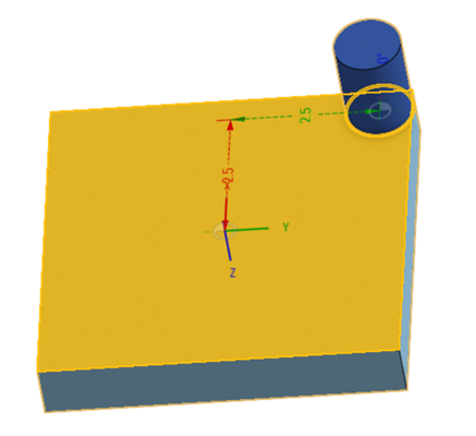
このシナリオでは、Y の値が正で、X の値が正であることに注意してください。これは、1つの合致コネクタから別の合致コネクタへの測定順序によるものです。2 番目に選択した合致コネクタから最初の合致コネクタまで、座標系に沿って測定が行われることを覚えておくことが重要です。
これらの距離の表示を使用して、[制限] ボックスに入力する値を推定します。
- 合致に対して [制限] チェックボックスが表示されている場合、クリックして自由度フィールドを有効にして、2 番目に選択した合致コネクタから最初に選択した合致コネクタまでの最小距離と最大距離の値を入力します。
- 距離の表示をガイドとして使用し (パーツをドラッグしてアクティブ化する)、最小値と最大値を入力します。
- 移動をその制限を含めてアニメートするには、[再生] ボタンを使用します。
アセンブリの数値フィールドでは、式と三角関数も使用できます。
Onshape は、どのインスタンスの自由度や動きが拘束されていないかを判断するための視覚的なインジケータを提供します。
インスタンスが任意の自由度内で移動できる場合は、リストのインスタンスの横にトライアドアイコンが表示されます。このアイコンにカーソルを合わせると、自由度があることを示すツールチップが表示されます。リスト内のロックアイコンでサブアセンブリの剛性を切り替えるか、サブアセンブリを右クリックして [位置のロック/フォロー] を選択します。現在の位置にロックするか、名前付きの位置をフォローするかを選択してください。
すべてのコンポーネントが完全に拘束されているサブアセンブリには、標準のアセンブリアイコンの代わりに剛体アイコンが表示されます。
最上位アセンブリアイコンは、アセンブリがスペース内でどのように拘束されているかを示します。固定してインスタンスを現在の場所と位置にロックすることも、原点に合致させて固定することもできます。アセンブリを別のアセンブリに挿入しても、どちらも引き継がれません。基本的なコンポーネントは 1 つだけこのように定義できます。
アセンブリの動きを観察する方法はいくつかあります。最も簡単なのは、アセンブリの可動インスタンスをクリックしてドラッグする方法です。動きは定義された合致フィーチャーに依存します。たとえば、スライダ合致は、このピストンサブアセンブリとバレルの間の自由度を制限し、直線的な自由度は 1 のみになります。この合致には限界があり、ドラッグできる範囲が限界となります。
トライアドマニピュレータは精度ドラッグが可能で、特定の値で動きを定義できます。
自由度のある合致はアニメートできます。リスト内の合致を右クリックして、[アニメート] を選択します。自由度が 1 以上の合致では、選択を促すプロンプトが表示されます。合致に制限が適用されている場合、開始値と終了値の距離は、既定でその制限の全範囲に自動的に設定されます。値を入力して可動域を指定します。[ステップ] はアニメーションの速度を定義します。値が小さいほどアニメーションが速くなり、値が大きいほどアニメーションが遅くなります。再生タイプで、[シングル] を選択してアニメーションを 1 回再生するか、開始値から終了値まで連続して再生し、手動で停止するまで戻るには [レシプロ再生] を選択し、手動で停止するまで最初から最後まで連続して再生するには [ループ] を選択します。アニメーションを逆にするには、矢印アイコンをクリックします。現在値は、アニメーション中に合致が動くときに入力される読み取り専用のフィールドです。
再生アイコンをクリックしてアニメーションを表示し、停止アイコンをクリックして停止します。
[アニメート] コマンド (合致および合致インジケータのコンテキストメニュー) を使用して、単一の合致 (または合致内の単一の DOF) からアセンブリを操作します。アセンブリ内の他の合致およびリレーションも適用されます。
合致の制限を定義した場合、これらの値はアニメーションの開始点と終了点として使用されます。
- 合致または合致インジケータを右クリックし、[アニメーション] を選択します。
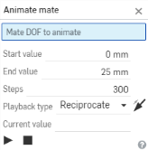
- アニメーション化では、一度に 1 つの自由度しか動作しないため、合致に複数の自由度がある場合は、1 つを選択するように求められます。
- [開始] と [終了] の値を入力します。[合致定義] で [制限] が指定されている場合、これらの値は [開始値] および [終了値] フィールドに自動的に入力されます。[合致] ダイアログで [制限] が指定されていない場合は、ここで値を入力します。
- 開始値 - 自由度の軸に沿って測定された最小距離です。(既定では、合致最小限界で指定された値)。
- 最終値 - 自由度の軸に沿って測定された最大距離です。(既定では、合致最大限度で指定した値)。
ここには最大 36000 度 (100 回転) を入力できます。特に、高比率の歯車およびラックアンドピニオンのリレーションで自由度を可視化するのに役立ちます。
- 開始から終了値までを含み、各手順で補間される線形マップで [手順] を指定します。手順の最小数は 2 です。既定では再生は約 60 手順/秒です。
- 再生タイプにシングルまたはレシプロを選択し、それぞれ、自由度のアニメーションを 1 回再生するか、手動で停止するまで連続的に再生します。
現在値は読み取り専用フィールドで、アニメーション中に合致が自由度を通過するときに、指定した単位で入力されます。モーションが (自動または手動で) 停止すると、現在値にはモーションが停止した点が表示されます。
[アニメート] はすべての合致タイプをサポートしますが、[固定]、[接線]、または [球] を使用して合致を操作することはお勧めしません。
ヒント
- [アニメーション化] コマンドは、分離、合致インジケータ、合致コネクタなど、さまざまなグラフィックモードで動作します。
- [アニメート] を使用すると、合致間の関係とその拘束システムを調査することができ、設計をより効果的に表示できます (特に回転の自由度に特化した再生ループフィーチャーで) 。
アセンブリが次の合致タイプで使用可能な間に、エンティティを互いにオフセットします。
- 平面オフセット - Z 軸方向
- スライダのオフセット - X 軸および Y 軸方向
- 回転オフセット - Z 軸方向
- ピンスロットオフセット - Z 軸方向
- ファスナーオフセット - X、Y、Z 軸方向
エンティティをドラッグして、グラフィック領域で距離の値を確認することもできます。これらは、ダイアログに入力する特定の値を決定するのに役立ちます。
アセンブリの数値フィールドでは、式と三角関数も使用できます。
アセンブリで合致されたエンティティをコピーして貼り付けることができます。
- エンティティを選択します。
- コンテキストメニューから、[アイテムをコピー] を選択します。
- コンテキストメニューから、アイテムを貼り付けます。
エンティティは、マウスクリックが発生した場所に直接貼り付けられます。
エンティティ、合致コネクタ、合致もアセンブリリストに複製されていることに注目してください。
合致は、アセンブリリストに表示されるだけでなく、グラフィック領域にもインジケータがあります。アセンブリリストでエンティティおよび合致コネクタを非表示にして、これらの合致インジケータをより明確に表示することができます。これらのインジケータは、定義する動作の種類、それに現在の状態を表すヒントになります。青または白は良好な合致を示し、灰色は抑制または非アクティブを示し、赤は問題を示します。合致および合致コネクタは、関連付けられるパーツやアセンブリが抑制されている場合は抑制されることに注意してください (抑制された合致は編集可能です)。


 ファスナー
ファスナー


 回転
回転


 スライダー
スライダー


 平面
平面


 円筒状の
円筒状の


 ピンスロット、スロットの方向に矢印がある


 球形
球形
![]()
![]()
![]() 平行
平行


 接線
接線
![]()
![]()
![]() 幅
幅


 グループ
グループ
合致を可視化するためのその他のヒントは以下のとおりです。
- パーツを選択し、右クリックしてコンテキストメニューから [合致を表示] を選択します。
- 合致を実行できるコンテキストメニューを右クリックすると、合致上でアクションを実行できます。
- グラフィック領域で合致、合致コネクタ、または合致リレーションを選択すると、関連するインスタンスと合致フィーチャーがリストに強調表示表示されます。
- 任意の 2 つのインスタンスの間には厳密に 1 つの合致があります。
- エンティティの固定は、合致の適用とは異なります。固定 (コンテキストメニューにあります) は、その適用先のアセンブリに固有です。エンティティが挿入されている他のアセンブリには引き継がれません。
- 合致は、2 つのインスタンスを互いに関連させて配置し、各インスタンスに合致コネクタを整列させます。
合致前
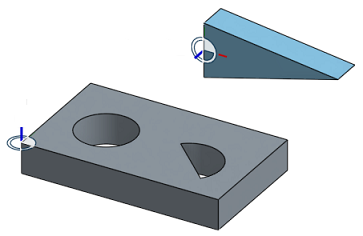
合致後
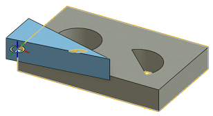
- 最初の位置は、多くの場合、最良の推測です。位置を修正するには、次の 2 つのツールがあります。
- [主軸を反転] ツールは、主軸 (Z) 方向を反転させます。


- [二次軸の向きを変更する] ツールは、90 度単位で方向を調整します
- 再生ボタン
 は、作成する合致間の許可された移動をアニメーション化します。
 - [解決] ボタンは、処理中の合致とすべての合致の移動を再生成するため、変更がアセンブリ全体にどのように影響するかを確認できます。
次に、[合致タイプ] で自由度の動作を指定します。
- 合致 (
 など) を選択してダイアログを開きます。
- 各エンティティ上の自動合致コネクタを 1 つ選択します (原点に合致させることもできます)。
- 必要に応じて、[主軸を反転] または [二次軸を回転] を使用して方向を調整します。
- 合致
 を確定します。
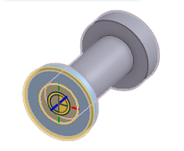
上記の例では、自動合致コネクタのみが使用されています。ほとんどの合致の場合、自動合致コネクタは正常に動作します。あまり一般的でないケースでは、合致コネクタを事前に作成すると便利です。アセンブリまたは Part Studio のいずれかで合致コネクタを作成できます。

Onshape での合致は、従来型 CAD システムの合致とは異なります。任意の 2 つのインスタンス間には Onshape の合致が 1 つだけ存在し、その 2 つのインスタンス間の移動 (自由度) が合致に組み込まれます。
アセンブリでは、エンティティを原点に合致させることができます。コンテキストメニューを使用して、割り当てられた合致の動きをテストするために、エンティティを固定することもできます。エンティティには、パーツ、アセンブリ、サブアセンブリ、スケッチ、サーフェスが含まれます。
合致は、合致ダイアログで定義されます。
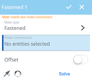
作成する合致のタイプを選択し、合致コネクタ (パーツごとに 1 つ) を選択します。
合致タイプ - 合致タイプ フィールドには、使用している合致のタイプが表示されます。タップして合致タイプのリストを開き、1 つを選択します。
合致コネクタ - 次の 合致コネクタ セクションでは、青で強調表示されます。これは、グラフィック領域からの選択が必要であることを示します。2 つの合致コネクタ (合致する各インスタンスから 1 つ) を選択する必要があります。
オフセット - タップして、合致するパーツ間の固定スペースを定義するオフセット距離を設定します。
制限 - タップして 移動距離の制限 を設定します。
![]() - インスタンスの主軸、Z 方向を反転します。
- インスタンスの主軸、Z 方向を反転します。
![]() - (XY 平面で) 二次軸の方向を変え、タップしてインスタンスを 90 度回転させます。
- (XY 平面で) 二次軸の方向を変え、タップしてインスタンスを 90 度回転させます。
解決 - タップして現在あるものを含むすべてのアセンブリ合致を解決します。
ボール、固定、接線以外のすべての合致の移動制限を指定できます。
制限 (回転、スライダ、平面、円筒、ピンスロット) を許可する合致のダイアログ内で、[制限] ボタンをオンにすると、制限フィールドが表示されます。
必要な制限仕様を入力し、[解決する] をタップして変更を視覚化します。
アセンブリが次の合致タイプで使用可能な間に、エンティティを互いにオフセットします。
- 平面オフセット - Z 軸方向
- スライダのオフセット - X 軸と Y 軸に沿って
- 回転オフセット - Z 軸方向
- ピンスロットオフセット - Z 軸方向
- ファスナーオフセット - X、Y、Z 軸方向
エンティティをドラッグして、グラフィック領域で距離の値を確認することもできます。これらは、ダイアログに入力する特定の値を決定するのに役立ちます。
アセンブリの数値フィールドでは、式と三角関数も使用できます。
合致は、アセンブリリストに表示されるだけでなく、グラフィック領域にもインジケータがあります。アセンブリリストでエンティティおよび合致コネクタを非表示にして、これらの合致インジケータをより明確に表示することができます。これらのインジケータは、定義する動作の種類、それに現在の状態を表すヒントになります。青または白は良好な合致を示し、灰色は抑制または非アクティブを示し、赤は問題を示します。合致および合致コネクタは、関連付けられるパーツやアセンブリが抑制されている場合は抑制されることに注意してください (抑制された合致は編集可能です)。
![]()
![]()
![]() ファスナー
ファスナー
![]()
![]()
![]() 回転
回転
![]()
![]()
![]() スライダー
スライダー
![]()
![]()
![]() 平面
平面
![]()
![]()
![]() 円筒状の
円筒状の
![]()
![]()
![]() ピンスロット、スロットの方向に矢印がある
ピンスロット、スロットの方向に矢印がある
![]()
![]()
![]() 球形
球形
![]()
![]()
![]() 接線
接線
![]()
![]()
![]() 平行
平行
![]()
![]()
![]() グループ
グループ
合致を可視化するためのその他のヒントは以下のとおりです。
- 2 本指でタップしてコンテキストメニューを開き、すべてを表示 をタップします。合致コネクタと合致インジケータを含む、インスタンスリストで一覧表示されているすべてのものを表示します。[すべて非表示] または [他の合致を隠す] も使用します。
- インスタンスリストで合致をタップします。
- 任意の 2 つのインスタンスの間には厳密に 1 つの合致があります。
- エンティティの固定は、合致の適用とは異なります。固定 (コンテキストメニューにあります) は、その適用先のアセンブリに固有です。エンティティが挿入されている他のアセンブリには引き継がれません。
- 合致は、2 つのパーツインスタンスを互いに関連させて配置し、各インスタンスで合致コネクタを位置合わせします。
合致前

合致後

- 最初の位置は、多くの場合、最良の推測です。位置を修正するには、次の 2 つのツールがあります。
![]() [主軸を反転] ツールは、主軸 (Z) 方向を反転させます。
[主軸を反転] ツールは、主軸 (Z) 方向を反転させます。
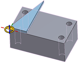
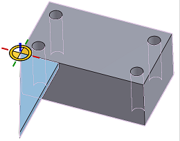
![]() 二次軸の向きを変更するツールは、90 度単位で方向を調整します。
二次軸の向きを変更するツールは、90 度単位で方向を調整します。
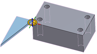
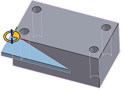
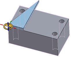
- 解決 ボタンは、処理中の合致とすべての合致の移動を再生成するため、変更がアセンブリ全体にどのように影響するかを確認できます。
合致タイプ は、移動動作を指定します。
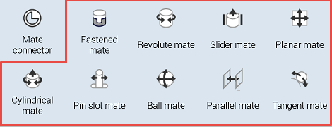
Onshape での合致は、従来型 CAD システムの合致とは異なります。任意の 2 つのインスタンス間には Onshape の合致が 1 つだけ存在し、その 2 つのインスタンス間の移動 (自由度) が合致に組み込まれます。
アセンブリでは、エンティティを原点に合致させることができます。コンテキストメニューを使用して、割り当てられた合致の動きをテストするために、エンティティを固定することもできます。エンティティには、パーツ、アセンブリ、サブアセンブリ、スケッチ、サーフェスが含まれます。
合致は、合致ダイアログで定義されます。
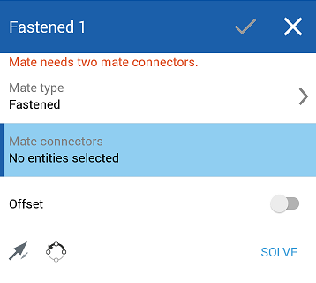
作成する合致のタイプを選択し、暗黙的または明示的な合致コネクタ (パーツごとに 1 つ) を選択します。
合致タイプ - 合致タイプ フィールドには、使用している合致のタイプが表示されます。タップして合致タイプのリストを開き、1 つを選択します。
合致コネクタ - 次の 合致コネクタ セクションでは、青で強調表示されます。これは、グラフィック領域からの選択が必要であることを示します。2 つの合致コネクタ (合致する各インスタンスから 1 つ) を選択する必要があります。
オフセット - タップして、合致するパーツ間の固定スペースを定義するオフセット距離を設定します。
制限 - タップして 移動距離の制限 を設定します。
![]() - インスタンスの主軸、Z 方向を反転します。
- インスタンスの主軸、Z 方向を反転します。
![]() - (XY 平面で) 二次軸の方向を変え、タップしてインスタンスを 90 度回転させます。
- (XY 平面で) 二次軸の方向を変え、タップしてインスタンスを 90 度回転させます。
解決 - タップして現在あるものを含むすべてのアセンブリ合致を解決します。
ボール、固定、接線以外のすべての合致の移動制限を指定できます。
制限 (回転、スライダ、平面、円筒、ピンスロット) を許可する合致のダイアログ内で、[制限] ボタンをオンにすると、制限フィールドが表示されます。
必要な制限仕様を入力し、[解決する] をタップして変更を視覚化します。
アセンブリが次の合致タイプで使用可能な間に、エンティティを互いにオフセットします。
- 平面オフセット - Z 軸方向
- スライダのオフセット - X 軸と Y 軸に沿って
- 回転オフセット - Z 軸方向
- ピンスロットオフセット - Z 軸方向
- ファスナーオフセット - X、Y、Z 軸方向
エンティティをドラッグして、グラフィック領域で距離の値を確認することもできます。これらは、ダイアログに入力する特定の値を決定するのに役立ちます。
アセンブリの数値フィールドでは、式と三角関数も使用できます。
[合致] は、アセンブリリストに表示されるだけでなく、グラフィック領域にもインジケータがあります。アセンブリリストでエンティティおよび合致コネクタを非表示にして、これらの [合致] インジケータをより明確に表示することができます。これらのインジケータは、定義する動作の種類、それに現在の状態を表すヒントになります。青または白は良好な [合致] を示し、灰色は抑制または非アクティブを示し、赤は問題を示します。[合致] および [合致] コネクタは、関連付けられるパーツやアセンブリが抑制されている場合は抑制されることに注意してください (抑制された合致は編集可能です)。
![]()
![]()
![]() ファスナー
ファスナー
![]()
![]()
![]() 回転
回転
![]()
![]()
![]() スライダー
スライダー
![]()
![]()
![]() 平面
平面
![]()
![]()
![]() 円筒状の
円筒状の
![]()
![]()
![]() ピンスロット、スロットの方向に矢印がある
ピンスロット、スロットの方向に矢印がある
![]()
![]()
![]() 球形
球形
![]()
![]()
![]() 接線
接線
![]()
![]()
![]() 平行
平行
![]()
![]()
![]() グループ
グループ
合致を可視化するためのその他のヒントは以下のとおりです。
- 2 本指でタップしてコンテキストメニューを開き、すべてを表示 をタップします。合致コネクタと合致インジケータを含む、インスタンスリストで一覧表示されているすべてのものを表示します。
- インスタンスリストで合致をタップします。
- 任意の 2 つのインスタンスの間には厳密に 1 つの合致があります。
- エンティティの固定は、合致の適用とは異なります。固定 (コンテキストメニューにあります) は、その適用先のアセンブリに固有です。エンティティが挿入されている他のアセンブリには引き継がれません。
- 合致は、2 つのパーツインスタンスを互いに関連させて配置し、各インスタンスで合致コネクタを位置合わせします。
合致前

合致後

- 最初の位置は、多くの場合、最良の推測です。位置を修正するには、次の 2 つのツールがあります。
![]() [主軸を反転] ツールは、主軸 (Z) 方向を反転させます。
[主軸を反転] ツールは、主軸 (Z) 方向を反転させます。


![]() 二次軸の向きを変更するツールは、90 度単位で方向を調整します。
二次軸の向きを変更するツールは、90 度単位で方向を調整します。


- 解決 ボタンは、処理中の合致とすべての合致の移動を再生成するため、変更がアセンブリ全体にどのように影響するかを確認できます。
合致タイプ は、移動動作を指定します。
ラーニングセンターに関するその他のリソースについては、こちらの技術説明記事: 合致の基本 (Onshape アカウントが必要) と 高度な合致テクニック (Onshape アカウントが必要) をご覧ください。
