Bauteile erstellen
Die Lektion dauert ca. 15 Minuten.
In diesem Abschnitt erfahren Sie, wie Sie in einem Onshape-Dokument mit einer Skizze mit der Erstellung von Bauteilen beginnen.
Der Basiscontainer in Onshape unterscheidet sich von den Dateien anderer CAD-Systeme. Onshape verwendet eine Struktur, die wir Dokument nennen. Dokumente können alle Arten von CAD-Daten und unterstützenden Materialien wie Bilder, Dateien, PDFs und mehr enthalten.
Um ein Bauteil in Onshape zu erstellen, müssen Sie zunächst ein Dokument anlegen (weitere Informationen zur Erstellung von Dokumenten finden Sie unter Skizze erstellen.
Bauteil von einer Skizze erstellen
Bauteile (Volumenkörper) werden aus Skizzenregionen erstellt (geschlossene Bereiche sind durch Schattierungen gekennzeichnet). Aus beliebigen Skizzenkurven können Oberflächen erstellt werden, auch wenn sie Teil einer geschlossenen Region sind.
- Wählen Sie das Tool „Linear austragen“
 in der Symbolleiste aus.
Das Dialogfenster wird angezeigt.
- Wählen Sie die umschlossenen (schattierten) Bereiche beider Rechtecke aus.
- Übernehmen Sie die Standardeinstellungen für die restlichen Felder im Dialogfenster.
- Klicken Sie auf das Häkchen, um die Aktionen zu übernehmen und das Dialogfenster zu schließen.
Die Bauteile sind in der Bauteilliste links (Bauteil 1 und Bauteil 2) aufgeführt.
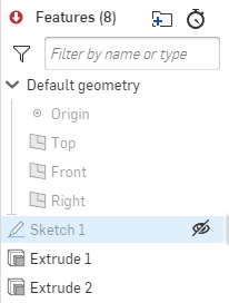
Sobald ein Bauteil aus einer Skizze erstellt wurde, wird die Skizze ausgeblendet. Um die Skizze wieder mit einem anderen Tool zu verwenden, bewegen Sie den Mauszeiger über den Namen der Skizze in der Feature-Liste und klicken Sie auf das Symbol „Anzeigen“:

Alle Skizzen, Features und Bauteile in den Listen auf der linken Seite können umbenannt werden. Klicken Sie mit der rechten Maustaste auf den Namen in der Feature-Liste oder Bauteil-Liste, um das Kontextmenü für ein Objekt aufzurufen.
Bauteil erstellen (Volumenkörper)
In Onshape können Features auf 2D-Skizzen in einem Part Studio zur Erstellung von 3D-Bauteilen angewendet werden. Alle Feature-Tools befinden sich in der Feature-Symbolleiste als Symbole oder in einem Dropdown-Menü, das an ein Symbol angefügt ist. Zwei Feature-Tools – „Linear austragen“ und „Rotieren“ – sind für einen einfachen Zugriff auch in der Skizzen-Symbolleiste verfügbar und können verwendet werden, wenn eine Skizze geöffnet ist. Beide Methoden zur Erstellung eines Bauteils werden hier behandelt (bei aktiver Skizze und nachdem die Skizze akzeptiert wurde).
Alle Skizzen und Features werden parametrisch in der Feature-Liste auf der linken Seite des Fensters gespeichert. Sie können alle Features und Skizzen, die in der Feature-Liste aufgeführt sind, erneut öffnen und bearbeiten (doppelklicken Sie, um das Dialogfenster zu öffnen oder klicken Sie mit der rechten Maustaste und wählen Sie „Bearbeiten“ aus).
Bauteil erstellen, wenn das Skizzen-Dialogfenster geöffnet ist
- Wenn eine vorhandene Skizze im Grafikbereich und das Dialogfenster „Skizze“ aktiv sind, klicken Sie auf „Linear austragen“
 .
.Onshape wählt automatisch alle Regionen aus (eingeschlossene Bereiche, die grau schattiert sind). Wenn Regionen verschachtelt sind, werden diese nicht ausgewählt. Onshape versucht, die Regionen auszuwählen, die sinnvoll sind.
An dieser Stelle können Sie weitere Regionen auswählen oder die Auswahl von Regionen aufheben.
- Nehmen Sie bei Bedarf Anpassungen an den Standardeinstellungen vor, einschließlich:
- Endtyp – Blind (für einen bestimmten Abstand), Symmetrisch (gleich in zwei Richtungen), Bis nächste (Material bis zum nächsten ausgewählten Element hinzufügen), Bis Fläche (Material bis zur nächsten Fläche hinzufügen), Bis Bauteil (Material bis zum nächsten Bauteil hinzufügen), Bis Scheitelpunkt (Material bis zum nächsten Scheitelpunkt hinzufügen, oder Durch alles (Material durch das gesamte vorhandene Material hinzufügen)
- Verwenden Sie die Pfeile, um ggf. die Richtung von der Ebene aus zu ändern, in der das Material hinzugefügt wird.
- Geben Sie eine Tiefe für das Material an.
- Sie können auch eine Formschräge (für jedes Material) erstellen oder eine zweite Endposition (für eine zweite Richtung) angeben. Diese Optionen werden unter Feature-Tool „Linear austragen“ erklärt.
- Klicken Sie auf das Häkchen
 , um das Feature zu übernehmen.
Bauteil erstellen, wenn das Skizzen-Dialogfenster geschlossen ist
- Nachdem Sie die Eingabe übernommen und das Skizzen-Dialogfenster geschlossen haben, klicken Sie auf „Linear austragen“
 .
.Der einzige Unterschied zwischen dieser Methode und der obigen Methode besteht darin, dass Onshape nicht automatisch alle Bereiche für Sie auswählt.
- Wählen Sie die Regionen aus, aus denen Sie Bauteile erstellen möchten. Denken Sie daran, für ein Volumenteil schattierte Bereiche auszuwählen.
- Legen Sie die Details wie oben beschrieben fest.
- Klicken Sie auf das Häkchen
 , um das Feature zu übernehmen.
Tastaturbefehle
- Mit dem Tastaturbefehl S zeigen Sie die Symbolleiste für das Feature an (bei geschlossenem „Skizzen“-Dialogfenster).
- Verwenden Sie Umschalt+E, um das Dialogfenster „Linear austragen“ zu öffnen.
- Klicken Sie auf das Fragezeichen
 und wählen Sie „Tastaturbefehle“ aus, um die Liste aller Tastaturbefehle in Onshape aufzurufen.
Bauteil verfeinern
Sobald Sie ein Bauteil erstellt haben, können Sie es mit den Onshape-Tools verfeinern, Verrundungen, Fasen und Formschrägen erstellen, ein Bauteil wanden und viele weitere Aktionen durchführen. Um die gesamte Liste der verfügbaren Tools zu sehen, bewegen Sie den Mauszeiger über die Symbole in der Feature-Symbolleiste. Hierbei werden auch Erklärungen und Kurzanleitungen für die einzelnen Tools angezeigt.
Dieses Beispiel erklärt das Anwenden von Verrundungen auf ein Bauteil.
- Sobald das Feature-Tool-Dialogfenster akzeptiert ist, klicken Sie auf „Verrundung“
 .
. - Wählen Sie die Kanten des Bauteils aus, die Sie verrunden möchten. Ausgewählte Kanten werden orange hervorgehoben.
- Optimieren Sie das Feature mit den Optionen im Dialogfenster, z. B:
- Tangentenfortsetzung: Ob Sie die Verrundungstangtialität entlang aller Tangentenflächen anwenden möchten oder nicht.
- Querschnittsstil: die Art der Verrundung: kreisförmig, konisch oder Krümmung. Überprüfen Sie die Querschnitte, um die Unterschiede zu sehen.
- Verrundungsradius: die erforderliche Größe der Verrundung.
- Variable Verrundung: Wählen Sie bestimmte Scheitelpunkte aus, um eine andere Verrundungsgröße anzuwenden. Geben Sie an, ob Sie einen reibungslosen Übergang zwischen den Verrundungen wünschen.
- Klicken Sie auf das Häkchen
 , um das Feature zu übernehmen.
Tastaturbefehle
- Mit dem Tastaturbefehl „P“ können Sie Ebenen ausblenden und Ebenen im Grafikbereich anzeigen.
- Richten Sie mit dem Tastaturbefehl „N“ die aktive Ebene senkrecht aus.
- Drücken Sie die Esc-Taste, um ausgewählte Tools zu deaktivieren.
- Drücken Sie die Eingabetaste, um Aktionen zu übernehmen und ein Dialogfenster zu schließen, sobald die erforderlichen Informationen eingegeben wurden.
- Wählen Sie das Tool „Linear austragen“ oder „Rotieren“ bei geöffnetem Skizzen-Dialogfenster aus. Onshape wählt dann automatisch alle umschlossenen Bereiche aus (einschließlich verschachtelter Bereiche):
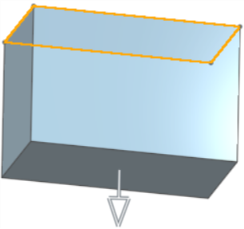
- Ziehen Sie den Bearbeitungspfeil, um Material beim Erstellen von Bauteilen zu verwenden (siehe unteres Beispiel).

- Verwenden Sie die Richtungspfeile
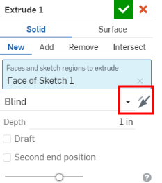
 in einem Dialogfenster (wenn verfügbar), um die Richtung der Aktion zu ändern (siehe Beispiel unten im Dialogfenster „Linear austragen“).

Weitere Learning-Center-Ressourcen finden Sie in den folgenden Kursen zum Selbststudium: Bauteil-Design mittels Part Studios (Onshape-Konto erforderlich) und Einführung in den Entwurf von Bauteilen (Onshape-Konto erforderlich).