 Revolute Mate
![]()
![]()
![]()
Mate two entities allowing rotational movement about the Z axis (Rz). Begin by creating Mate connectors on each entity, or use the implicit Mate connectors visible upon hover.
Introducing Onshape’s first three mate features in the toolbar: Fastened, Revolute, and Slider.
The Fastened mate restricts all degrees of freedom, creating no movement between the mate connectors. A bolt in a hole or two instances welded together are simple examples of when no movement is needed between instances. Start a Fastened mate.
For this example, the first point to select is in the center of the hole where the rod is inserted. The second point to select is the centroid on the end face of the rod. Circular faces and edges are quick selections for mate connector points because the only point available is the centroid.
The two instances move so that the mate connectors touch. Check Offset and enter a value for the Z axis to create room at the end of the rod for fasteners. If the offset should be in the opposite direction, make the value negative.
Hover over the mate in the Mate Features list to see the defined options without returning to the dialog.
The Revolute mate provides one degree of freedom with a rotation about the Z axis. Start a Revolute mate.
For this example, a mount is mated to the bottom of the rear cap, which should swivel to accommodate the varying positions of this assembly when it is inserted into other assemblies. The first selection is the centroid on the top face of the mount. The second selection is the centroid on the bottom face of the rear cap.
Animate to see the revolute’s degrees of freedom.
The Slider mate provides one degree of freedom with translation along the Z axis. Start a Slider mate.
For this example, the piston should slide up and down in the barrel. The first point to select is the centroid of the top face of our bottom cap. The second point to select is the centroid of the bottom piston face. The instances move into position where the mate connectors touch.
Animate to see the range of motion. To restrict the distance the piston travels along the primary axis, enable Limits. The value entered should keep the Piston from colliding with the top cap. If the limit is set in the wrong direction, make the value negative.
Steps
- Click
 .
.
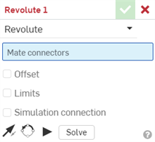
- To limit the movement, check Limits and supply (optional) minimum and maximum values to control the range of motion of the Mate.
Limits are visualized in the graphics area as dashed lines with bars at the ends. The dashed lines represent the direction and distance of the movement and the solid lines represent the limit.
If a Mate has one or more applied limits, the Mate limit indicator icon
 is visible to the right of the Mate in the Mate Features list.
 - To supply an offset distance, check Offset and supply a distance. Revolute Mates are able to offset the entities along the Z axis only. To create an offset between the two entities, click Offset and specify a distance.
Offset distances are visualized in the graphics area as dashed lines between the Mates, displaying the value and the axis. Enter the distance in the dialog.
When you click on a Mate, graphics are displayed to indicate the direction of the X, Y, and Z as defined by the Mate along with the offset and the range of limits dimensions (if any).
Applying an offset should be viewed as moving the entire coordinate system. The offset is relative to the Mate connector selected first.
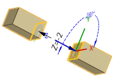
You can also select to rotate the part about a specific axis: select the axis, then enter the degrees of rotation.
- Click an entity to access the manipulator.
- Click and drag the various manipulator handles to see which motions are allowed; notice that only rotational movement about the Z axis is allowed (Rz).
The first Mate connector selected serves as the rotational point and the second Mate connector selected serves as the stationary point.
Editing a Mate connector
Once a Mate is created between two explicit or implicit Mate connectors, you can edit either Mate connector:
-
Open the Mate dialog. In the example below, the Fastened mate is used as an example. The process is similar for all Mates, except Tangent mate which does not use Mate connectors.
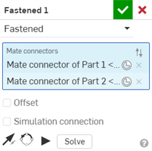
-
Click the Mate connector icon (
 ). The Mate connector dialog opens, where you can edit the mate connector's origin type, origin entity, alignment, location, primary axis direction, and secondary axis orientation:
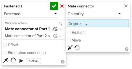
Editing Mate connectors from the Mate dialog is limited to implicit or explicit connectors located in the current Assembly. Mate connectors from Part Studios, subassemblies, or linked documents must be edited in their original location.
Steps
-
Tap the Revolute mate icon
(
 ).
).
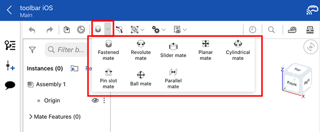
- Confirm that Revolute is selected in the Mate type field.
- Select two Mate connectors to use.
- Optionally, tap Offset to provide an offset distance.
- Optionally, tap Limits to set distance limits for movement.
-
Optionally, tap
 to Flip the primary axis, Z orientation of the instances.
-
Optionally, tap
 to Reorient the secondary axis; rotate the quadrant orientation (in the XY plane) of the instances by 90 degrees at a tap.
- Tap checkmark.
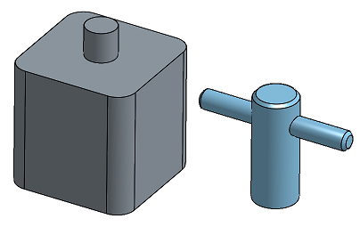
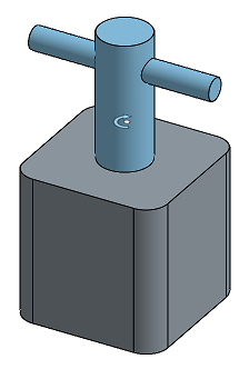
Touch and drag OR use the Triad Manipulator to move one of the parts. Notice that only rotational movement about the Z axis is allowed(Rz).
Steps
-
Tap
 .
.
- Confirm that Revolute is selected in the Mate type field.
- Select two Mate connectors to use.
- Optionally, tap Offset to provide an offset distance.
- Optionally, tap Limits to set distance limits for movement.
-
Optionally, tap
 to Flip the primary axis, Z orientation of the instances.
-
Optionally, tap
 to Reorient the secondary axis; rotate the quadrant orientation (in the XY plane) of the instances by 90 degrees at a tap.
- Tap checkmark.
Touch and drag OR use the Triad Manipulator to move one of the parts. Notice that only rotational movement about the Z axis is allowed(Rz).

