 Mass Properties Tool
![]()
![]()
![]()
The Onshape Mass properties tool is available in Part Studios and assemblies. Find the Mass properties tool in the bottom-right corner of the desktop interface or on the main mobile toolbar.
You can also use this tool to override properties and supply your own values for mass.

Properties are additive: for each additional part you select, its properties are added to the calculations in the dialog (desktop) or panel (iOS and Android). When you apply materials to parts, the density of the material is used in the calculations in the Mass and section properties dialog/panel. If a part has no material assigned, no figure for that part is used in the calculation (and a note is displayed in the dialog/panel to that effect).
Results of mass property calculations are approximate. The calculation of the properties may vary in accuracy, depending on the complexity of the geometry.
Enabling Show calculation variance displays the value and the difference between the lower and upper bound of the calculated value. If Show calculation variance is not enabled, the computed value without the bounds is displayed. The computations of the values are not affected by the state of the Show calculation variance checkbox.
Apply Materials to parts through the context menu on a part in the Parts list (or the graphics area).
Onshape’s Measure and Mass properties tools allow designers to initiate critical design checks. The Measure tool is available in Part Studios and Assemblies. It is also available on drawings in a limited capacity.
Select one or more faces, edges, or vertices for a quick measurement without activating the Measure tool. Click Show measure details. Specify the Measurement type. When left at Show all, results for each measurement type are shown. For a specific type, set this to another option, such as Position, Radius, or Min distance. Specify the units of measurement for both Length and Angle. Change units at any time.
Select entities to measure in the graphics area. The results differ depending on the selections. If more than 2 items are selected, Onshape displays the total surface area and length of the selections. Selecting faces adds to the total surface area, while selecting edges adds to the total length. Selecting 2 lines identifies whether lines are parallel to each other. Several measurements are available: Parallel distance, Maximum distance, and Minimum distance. Each measurement also indicates the distances between the selections along the world axes. Selecting two fillet faces displays the dimension between their parallel axes, the total area, and the minimum and maximum distances.
Quickly create a driven or measured variable by clicking the variable icon beside any measurement, including quick measurements. The variable's value updates if the corresponding measurement changes. See mass properties calculations for faces and parts in Part Studio and Assembly tabs. Click Display mass and section properties. Click the Part tab for part calculations using the density of assigned materials. If no material is assigned, the instances are not used in the calculations.
The mass of each instance, the total mass of multiple instances, or the entire Assembly is calculated. Additionally, the Volume, Surface area, Center of mass, and Mass moments of inertia are determined. Click the Face tab to show face calculations. Select a face, including section view faces, or coplanar selection of faces. The results display the Surface area, Perimeter, and both Area and Polar moments of inertia. The results of mass property calculations are approximate. Depending on geometric complexity, the accuracy of the property calculations may vary. Enable Show calculation variance when necessary. Select any resultant value in the Measure tool or Mass properties to copy the value and use it elsewhere. Clicking the value once displays and selects the numerical value to its full precision or all decimal places. Clicking it again shortens the precision to match the Workspace units setting.
-
To open the Mass and section properties dialog, click the small scale icon
 in the bottom-right corner of the interface.
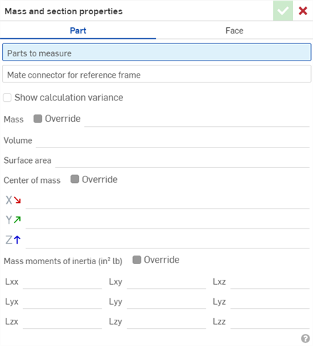
- Select either the Part tab to get the mass properties for an entire part(s) or the Face tab to get the mass properties for a cross section or face(s).
- Make your selections in the graphics area.
- If you wish to override calculations and enter your own mass values, select the entire part or assembly in the Features or Instances list on the left. Then, check the Override box and enter the desired value. Appropriate recalculations are made once a new value is entered.
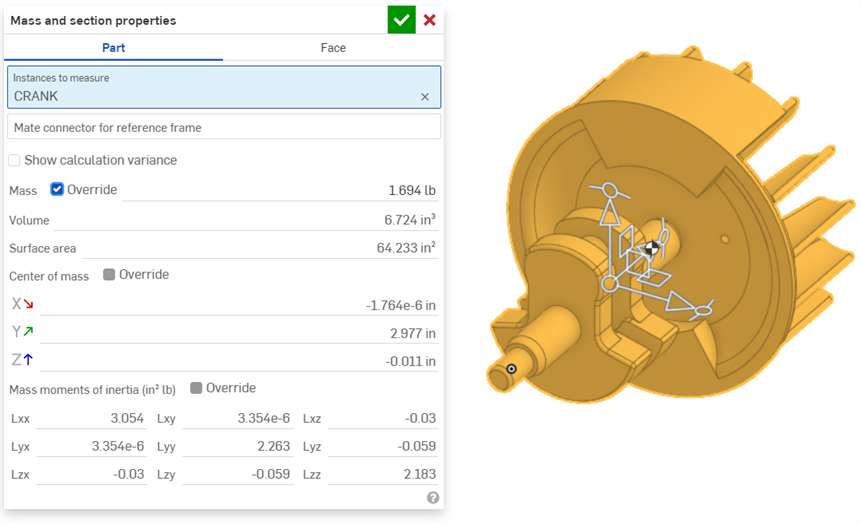
The center of mass is marked with
![]() on the model when the Mass and section properties dialog is open, as shown in the image above and in the image below.
on the model when the Mass and section properties dialog is open, as shown in the image above and in the image below.
For any intersecting parts, the properties are calculated for each individual whole part and added together.
The Mass and section properties dialog provides the following information, presented from top down as shown in the tool:
- Parts/faces/instances to measure - Click a face or part in the graphics area or Features/Instances list to add it to the calculations.
- Select a mate connector, implicit or explicit (optional), to calculate the moments of inertia more accurately (instead of to the center of gravity of the selected parts):
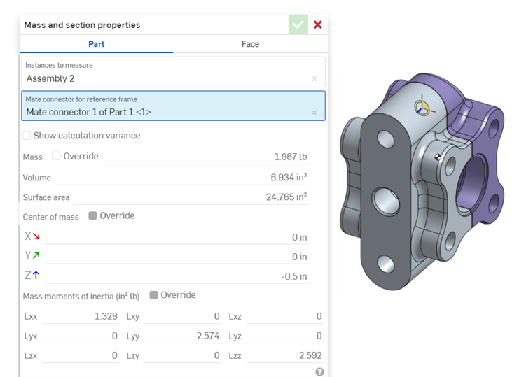
- Mass of all parts that have a material applied
- Volume of all selected parts
- Surface area of all selected parts or faces
- Perimeter of all selected faces
- Center of mass of all parts that have a material applied
- Moments of inertia
- Calculated with respect to the center of gravity of the selected parts/faces (not the Part Studio/assembly origin)
- For parts, calculated using the densities of the assigned materials assigned. Any selected parts without materials assigned are omitted from the calculation. If no materials are assigned to any selected parts, no calculation is made.
You can use the information shown in the Mass and section properties dialog to enter values elsewhere in the system (for example, as a dimension).
-
With the Mass and section properties dialog expanded, click the value to view and highlight the max precision.
-
Click again to toggle the view to value with default decimal place setting.
Use native shortcut keys to copy values to the clipboard.
Tap the Mass properties tool icon (![]() ) on the iOS toolbar:
) on the iOS toolbar:

If you want to override calculations and enter your own values for Mass, select the entire assembly in the Instances list on the left. Then place a check in the Mass Override box and enter the desired value. Appropriate recalculations are made once a new value is entered:
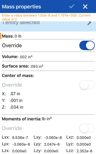
- To use the Mass properties tool; either select the tool and the parts/faces/instances to measure. You can also select the parts/faces first, then select the tool.
- You can select multiple parts/faces at a time.
- Parts and faces may be selected in both the graphics area and the Features, Parts, and Instances lists.
The Mass Properties dialog provides the following information, presented from top down as shown in the dialog.
The information is presented in the default units that you have set for your document. The image above is displaying mass property information in terms of inches (the default unit for this document).
To change the default units for your document, tap the Document menu icon the upper left, select
Units, and select desired length, angle, and mass units.
- Parts/faces/instances to measure - Tap to view the list of selected entities. Swipe left on an entity in the list to reveal a delete option.
- Mass of all parts that have a material applied
- Volume of all selected parts
- Surface area of all selected parts or faces
- Perimeter of all selected faces
- Center of mass of all parts that have a material applied
- Moments of inertia
- Calculated with respect to the center of gravity of the selected parts/faces (not the Part Studio/assembly origin)
- For parts, calculated using the densities of the assigned materials assigned. Any selected parts without materials assigned are omitted from the calculation. If no materials are assigned to any selected parts, no calculation is made.
If you select more than one part/face at a time, the combined properties of the parts/faces are calculated. Any intersecting parts/faces have the properties of each individual whole part/face calculated and added together.
If you want to override calculations and enter your own values for Mass, select the entire part, face, or assembly, then check the Mass Override box and enter the desired value. Appropriate recalculations are made once a new value is entered.

Mass Properties tool shown in Part Studios toolbar on Android application.

Mass Properties tool shown in Assemblies toolbar on Android application.
- To use the Mass properties tool; either select the tool and then select the part(s) OR select the part(s) first and then the tool.
- You can select multiple parts/faces at a time.
- Parts and faces may be selected in both the graphics area and the Parts/Features/Instances lists.
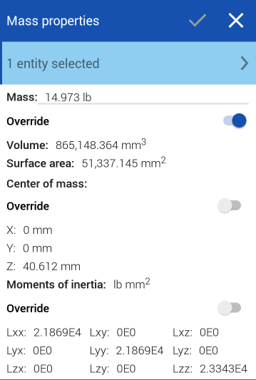
The Mass Properties dialog provides the following information, presented from top down as shown in the dialog.
The information is presented in the default units that you have set for your document. The image above is displaying mass property information in terms of inches (the default unit for this document).
To change the default units for your document, tap the Document menu icon the upper left, select
Units, and select desired length, angle, and mass units.
- Parts/faces/instances to measure - Tap to view the list of selected entities. Swipe left on an entity in the list to reveal a delete option.
- Mass of all parts that have a material applied
- Volume of all selected parts
- Surface area of all selected parts or faces
- Perimeter of all selected faces
- Center of mass of all parts that have a material applied
- Moments of inertia
- Calculated with respect to the center of gravity of the selected parts/faces (not the Part Studio/assembly origin)
- For parts, calculated using the densities of the assigned materials assigned. Any selected parts without materials assigned are omitted from the calculation. If no materials are assigned to any selected parts, no calculation is made.
If you select more than one part/face at a time, the combined properties of the parts/faces are calculated. Any intersecting parts/faces have the properties of each individual whole part/face calculated and added together.
If you want to override calculations and enter your own values for Mass, select the entire part, face, or assembly, then check the Mass Override box and enter the desired value. Appropriate recalculations are made once a new value is entered.