 Hole/Thread Callout
![]()
Apply a hole callout to a hole or thread, automatically inserting the metadata of the hole or thread.
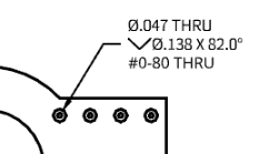
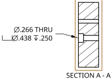
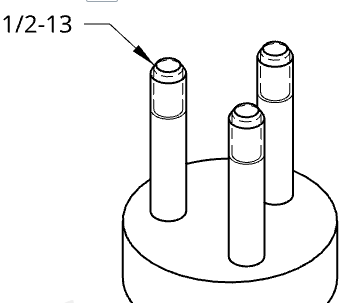
Steps
Creating a hole or thread callout:
-
Click
 .
.
- Select a circle that is part of a hole feature, or a thread that is part of an external thread feature.
-
Drag to place the callout.
If the selection was part of a hole feature, the precision, tolerance, fit class tolerance, and shaft class tolerance values from that feature are automatically applied. To override these values, see Editing a callout section below.
The leader includes a moveable node along the horizontal segment.
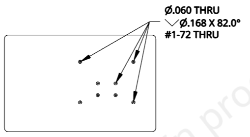
You can add multiple leaders to more holes, as long as the holes are the same size:
- Right-click the callout and select Add leader.
- Click on another hole.
- Repeat as necessary to add leaders to as many same-size holes as necessary.
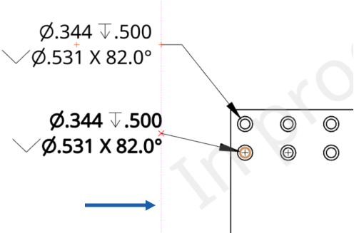
While moving the mouse to place the callout, you'll notice thin, red, dashed lines as the cursor passes near other entities (shown below to the right of the blue arrow). These are inferencing lines that you are able to align the dimension to; simply click when you see the line appear to align the dimension to that line.
Editing a callout
You can edit a callout once it is placed: double-click on the callout to open the panel:
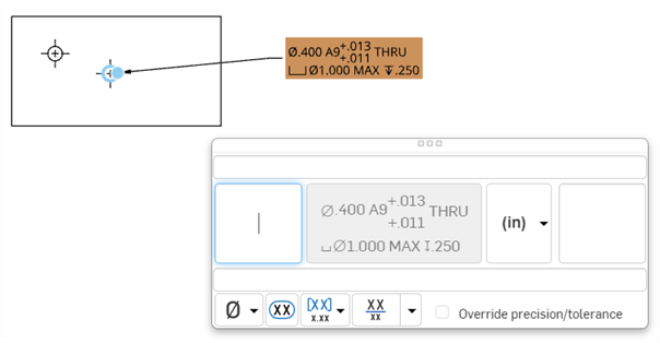
Use the panel to edit characteristics such as:
- Above text - Enter the text or symbol to appear above the dimension value.
- Prefix text - Enter the text to appear as a prefix to the dimension value.
- Count type - Use the dropdown to select a count type for the callout:
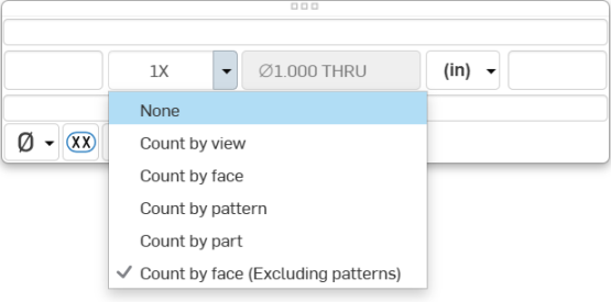
If the callout is placed on a hole that is part of a pattern, the Count by face (Excluding patterns) option becomes unavailable.
- Units - Select the units of your choice. The currently selected unit is displayed in the dropdown label.
- Suffix text - Enter the text to appear as a suffix to the dimension value. -
- Below text - Enter the text or symbol to appear below the dimension value.
-
Symbol dropdown - Select a symbol to insert from the dropdown.
- Inspection dimension - Toggle to add or remove an oval frame around the dimension to indicate this is an inspection dimension.
- Single dimension or dual dimension selection - Dual dimensions may be top/bottom or side-by-side.
- You can set precision and tolerance precision per parameter by checking the Override precision/tolerance box:
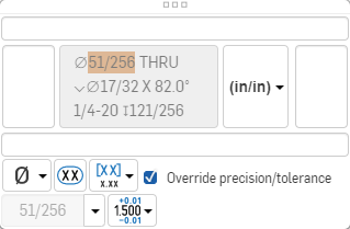
Use the menus to select a new precision and/or tolerance for the selected hole/thread or collection of holes created by the feature.- Precision - Select the depth of unit precision (zero to 8 decimal places).
- Tolerance
- Select None, Symmetrical, Deviation, Limits, Basic, MIN, MAX, Fit, Fit with tolerance, or Fit (Tolerance only).
- Set the upper and lower tolerance (available for Symmetrical, Deviation, or Limits)
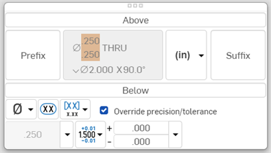
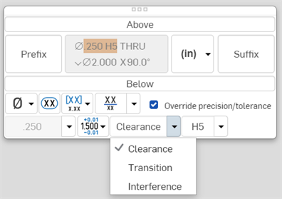
- Set the Fit type and Hole class (available for Fit, Fit with tolerance, or Fit (Tolerance only))
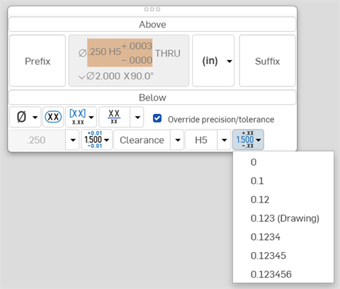
- Set the precision depth of the Fit tolerance units, from 0 to 8 decimal places (available for Fit with tolerance or Fit (Tolerance only))
- Set the shaft class visibility (available for Fit and Fit with tolerance options):
- Shaft fit class information is hidden by default in Hole callouts and Hole tables in drawings.
- Click the Toggle shaft class visibility button to toggle between display styles.
- Click the Toggle shaft class visibility dropdown to select a display style.
- Set the upper and lower tolerance (available for Symmetrical, Deviation, or Limits)
Hole drawing lines
The image below depicts an ANSI tapered pipe tap hole drawing:
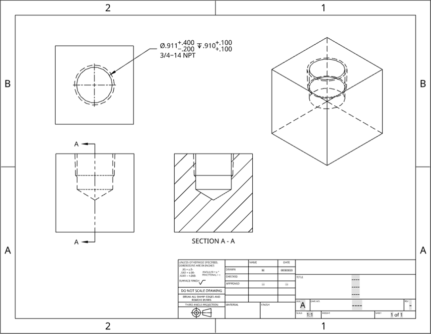
Threads on tapped and tapered pipe tap holes are indicated by dashed lines for ANSI drawings, and the appropriate 3/4 outline for ISO drawings. An ANSI drawing is illustrated below:
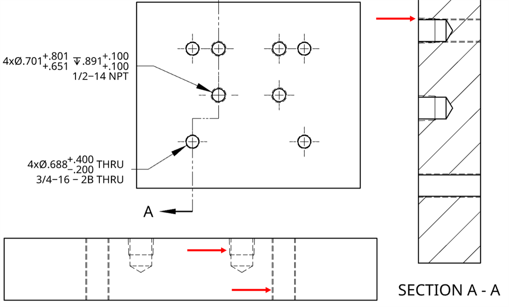
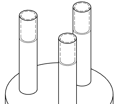
When a part occludes part of thread, the occluded threads are not shown, as shown below:
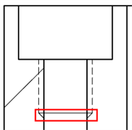
For threaded holes, the representation of the threading tool pulling away from the workpiece is a 45 degree tapered transition that extends from the external and internal threads to the cylinder edge (outlined in red below):
To show/hide thread lines:
- Right-click on the view.
- Select Show/Hide threads (to toggle thread lines on and off).
Thread drawing lines
The image below depicts a thread on a 3/4inch ANSI standard bolt with 10 threads per inch:
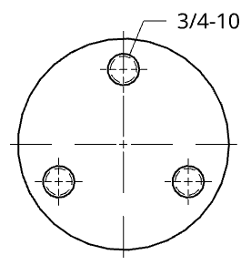
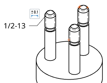
Bolts with a chamfer applied through the External thread feature have dashed lines representing the threads in the drawing view:

Bolts with an undercut applied through the External thread feature show both the undercut and the dashed thread lines in the drawing view:
Styling a callout
To style a callout:
-
Click on the callout you want to style, then click the Styles panel icon on the right side of the page:
-
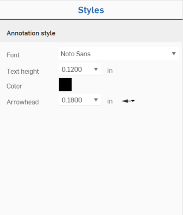
This opens the Styles panel, where you can edit the font, text height, color, arrowhead, and text justification of the callout:
![]()
