


iOS and Android support for the sheet metal Jog feature is limited to viewing and editing jogs that are created from the desktop (browser) platform.
Available in: Part Studio
Offset a sheet metal model at a reference line with two bends in opposite directions with additional jog controls to define its offset, angle, alignment, and orientation. The result forms an S- or Z-shaped curve in the sheet metal.
A jog is often used where two pieces of sheet metal come together, and a flush seam is desired. A jog can be placed along edges, surfaces, or at specific locations on the sheet metal part.
 Steps
Steps
To create a jog:
- While in a Part Studio, click the Sheet metal jog icon (
 ) on the Feature toolbar.
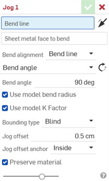
- Select the Bend line in the Graphics area where the jog should occur.
- Select the Sheet metal face to bend. Only one face can be jogged per feature.
- Click the Hold opposite side arrow (
 ) to jog the opposite side of the sheet metal face.

Default side (left), Hold opposite side (right)
- Select the Bend alignment:
- Bend line - Align the bend line to the middle of the jog in the sheet metal flat pattern.
- Hold line - Align the bend line to the start of the jog in the sheet metal flat pattern.
- Hold other line - Align the bend line to the end of the jog in the sheet metal flat pattern.
- Inner - Align the inside of the bent wall with the bend line.
- Outer - Align the outside of the bent wall with the bend line.
- Middle
- Align the mid-plane of the bent wall with the bend line.
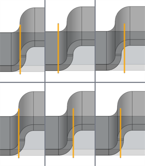
Bend alignment examples with Bend line highlighted orange: Bend line (top left), Hold line (top middle), Hold other line (top right), Inner (bottom left), Outer (bottom middle), Middle (bottom right)
- Select a Angle control type:
Bend angle - Align the bend parallel to the Bend line.
Bend angle - Enter a Bend angle from 1 to 359 degrees from the Bend line. Optionally, click the Opposite angle (
 ) to flip the Bend angle.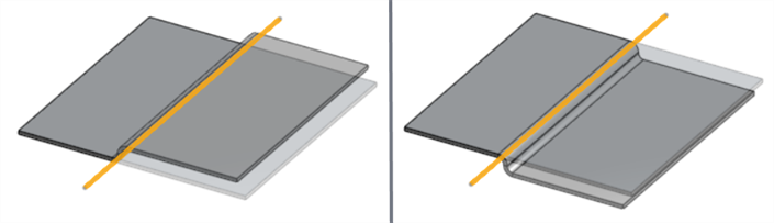
Bend angle: 90 degrees; default angle (left), Opposite angle (right); bend line highlighted orange.
Align to geometry - Align the bend parallel to the selected geometry.
Parallel to - Select an edge, face, or plane for the bend's parallel alignment.
Align from direction - Align the bend directionally from the selected geometry. Use the Opposite direction angle arrow (
) to flip the angle's direction.Direction - Select an edge, face, or plane for the bend's directional alignment.
Angle - Enter the bend angle from 1 to 180 degrees from the selected Direction edge, face, or plane.
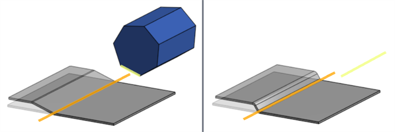
Left: bend line (orange) aligned to geometry (parallel to the yellow polygon edge); Right: Bend line (orange) angled from direction (yellow sketch line)
-
Keep Use model bend radius checked to use the inside bend radius specified for the sheet metal model, or leave unchecked to enter a custom Bend radius value.
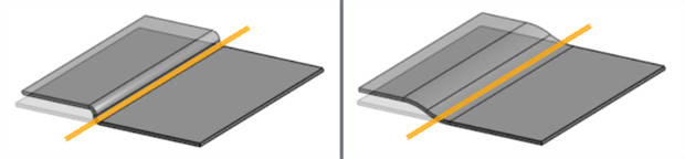
Left: Use model bend radius checked (0.23 cm); Right: Use model bend radius unchecked (Bend radius: 2.5 cm)
-
Keep Use model K factor checked to use the Sheet metal model Feature's K factor value, or leave unchecked to enter a custom K Factor value.
-
Select a Bounding type:
-
Blind - Offset the jog to a specified distance in the Jog offset field.
-
Up to entity - Offset the jog to a specified entity. Check Offset distance and enter an additional distance to offset beyond the selected entity.
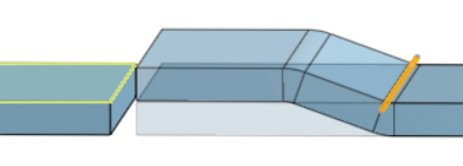
The bottom of the sheet metal jog is bounded up to the opposing sheet metal's top face (in yellow)
-
Thickness - Enter a Thickness factor to offset the jog by a factor of the Sheet metal model's Thickness parameter. For example, if the Sheet metal model's Thickness is 0.5 cm, a Thickness factor of 4 offsets the jog by 2 cm.
-
-
Select the Jog offset anchor to define how the height of the jog is measured relative to the sheet metal face:
-
Inside - Defines the distance from the top sheet metal face to the inner parallel surface of the jog (shortest distance).
-
Nominal - Defines the distance from the bottom of the sheet metal face to the outer surface of the jog. This accounts for the overall height of the profile and is also called the Overall dimension.
-
Outside - Defines the distance from the top sheet metal face to the outer parallel surface of the jog.
-
-
With Preserve material checked (default), no additional sheet metal material is added as a result of the jog. Uncheck to add material to the sheet metal to compensate for the jog. This maintains the sheet metal's original length before the jog was applied.
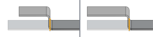
Left: Preserve material checked; Right: Preserve material unchecked
-
Click the checkmark (
 ) to accept the Jog feature.
To modify a Jog after it is created, use a direct edit tool such as Move face.
Notes
Bend line
The Bend line does not necessarily indicate the line on which the bend occurs.
-
It does not have to be coincident with the selected face. It is projected onto the face.
-
It does not have to fully cut the selected face. It is extended to the edges of the face.
-
It does not have to be part of any sketch.
-
It can extend along multiple cuts in the same face.
-
In most cases it can be any angle to the selected face. Certain cases with complex reference geometry produce an error.
General
-
A bend cannot interfere with any previous Bend or Corner features in the Features list. This causes a collision in the Sheet metal model and produces an error. You can, however, create bends in flange and hem faces.
-
Using a custom K factor value modifies the effective length of the bent metal in the 3D model only.
-
The Bend allowance or Bend deduction value cannot be edited from the Bend dialog. Adjust this value in the Sheet metal model feature or open the Sheet metal table and flat view, and double-click the table cell to edit the value directly. See Editing sheet metal in the table.
-
The bend does not affect dimensions of the Sheet metal flat pattern if Preserve material is checked.
Examples
Overlap
-
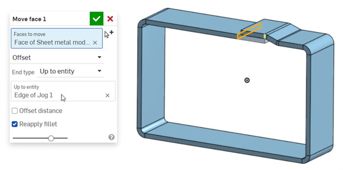
The jog is created in the middle of one of the ends of the sheet metal sides (Bend line in orange), with a 0.01 cm Offset distance, to prevent sheet metal collision:
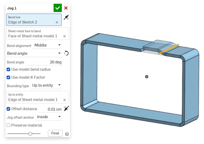
-
A Move face feature is then created to move the opposing sheet metal end face beneath and up to the edge of the jog (Face to move in orange; Up to entity in yellow):
Circular sheet metal jog
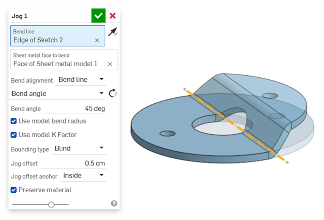
Example adding a jog on a washer:
Sleeve insert
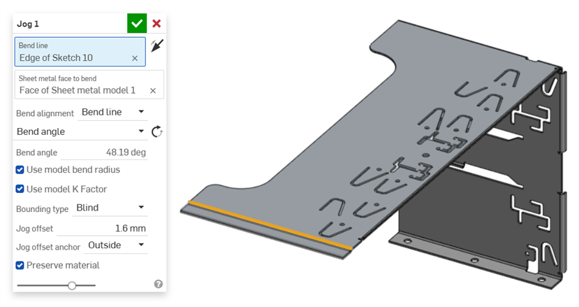
Example of a jog used on the edge of a metal case sleeve insert:
Additional sheet metal tools
When a sheet metal model is active (in the process of being created or edited), additional tools are available:
-
 Flange - Create a wall for each edge selected, connected to the selected edge with a bend.
 -
 Hem - Create a hem for each edge/face selected, on an existing sheet metal part.
 -
 Tab - Add a tab to a sheet metal flange.
 -
 Bend - Bend a sheet metal model along a reference line, with additional bend control options.
 -
Jog - Offset a sheet metal model at a reference line with two bends in opposite directions with additional jog controls to define its offset, angle, alignment, and orientation. The result forms an S- or Z-shaped curve in the sheet metal.
-
 Form - Create form features on existing sheet metal models. Forms can be selected from the current document, other documents, or a predefined library of sheet metal forms.
 -
 Loft - Create sheet metal models that connect two profiles.
 -
 Make joint - Convert the intersection of two walls into a joint feature, either a bend (walls joined by cylindrical geometry) or a rip (small gap between two walls).
 -
 Corner - Modify a corner type and relief scale.
 -
 Bend relief - Modify a bend relief (the small cut made where the bend end meets the free edge), depth and relief width.
 -
 Modify joint - Make changes to an existing joint, such as converting a bend to a rip. Currently available through the flat view table.
 -
 Corner break - Break the corner on existing sheet metal parts by applying a fillet or chamfer. Select a corner edge or vertex and specify corner break type and distance. It is recommended to use this feature after all flanges and joints of the Sheet metal model are finalized.
 -
 Sheet metal table and flat view - Open and close the Rip/Bend tables and the visualization of the sheet metal model flat pattern. Use this table to convert rips to bends and vice versa.
 -
 Finish sheet metal model - Closes (deactivates) the Sheet metal model; creates a feature in the Feature list.