 Drawing - Ordinate Dimension
![]()
Available in: Drawing
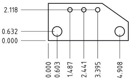
Create ordinate dimensions (X, Y pairs) for a feature measured from a datum. Ordinate dimensions created as a group move together when one is moved.
-
Click
 .
.
- Click the point to serve as the datum (0, 0). Points may include edges and lines, arc, and centermarks as well as manually placed centermarks.
- Click each point in one direction (Y, for example) to associate with that datum point.
- Press Escape to exit the tool.
At this point, one Ordinate dimension group is created.
-
Click
.
- Click the point to serve as the datum (0,0).
- Click each point in the other direction (X, for example) to associate with that datum point. This datum is able to be the same as the first datum chosen.
- Press Escape to exit the tool.
At this point, a second Ordinate dimension group is created.
If the orientation of the ordinate dimension is not correct, move the mouse around the datum point until the 0,0, dimension is in the correct orientation, then click to set its location on the drawing.
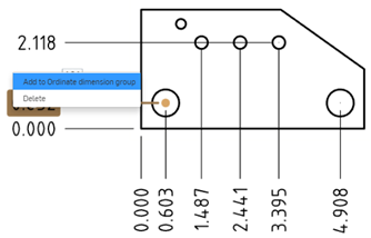
Right-click on an ordinate dimension access the context menu for the ordinate dimension group:
- Add to ordinate dimension group - Select to add another ordinate dimension to the existing group; click a point to act as a datum point.
- Edit - Select to open the Dimension palette for the ordinate dimension group.
- Reset ordinates - If you've moved the ordinate dimension out of its original alignment, select this option to automatically move it to its previous position.
- Clear selection - Clear all selected items.
- Zoom to fit - Zoom the drawing to fit in the view.
- Delete - Delete the selected items.
-
Use the inferencing to make realigning the datum points easier. Click and drag a datum point (it doesn't matter if it's a jogged position or not) to activate inferencing guidelines.
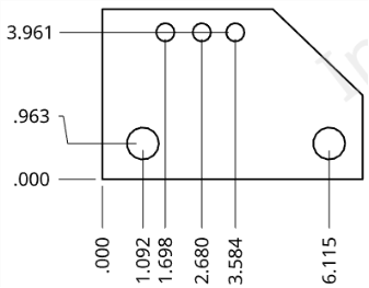
For example, to unjog the .963 datum point below:
Click and drag until the desired inferencing guideline appears, then release to place the datum point.
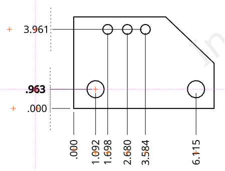
The bold datum point (.963 to the left, above) is the point being realigned; the red crosses (plus signs) on each datum point are alignment snap indicators
The guidelines come in especially handy when trying to jog or unjog datum points.
-
Grouped ordinate dimensions can be moved as a group or singly. Drag the middle snap point of the dimension, notice the dashed lines appear on all dimensions in the group, and drag the dimension to a new position and all members of the group move in sync:
Use the outmost snap point (below, on the far right) to drag a singular dimension on its own:
If you subsequently move any of the group, all are moved in their relative positions, as indicated by the dashed lines:
- Circular grip points at arrow bases flip the arrows to the opposite side of the dimension lines.
- Each direction must have a datum; each time you initiate the command from the toolbar, the first click establishes the datum point (0, 0).
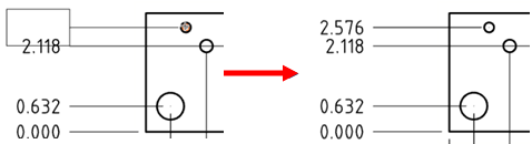
- Each direction of dimensions (Y, for example) consists of an ordinate dimension group with a single datum. To add another value pair to that group, select an existing value in the group, right-click and select Add to ordinate dimension group. This activates the command and the next click establishes the additional dimension value:
-
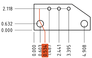
If the drawing is updated such that the feature an ordinate dimension refers to is removed, the ordinate dimension remains and turns red. You can safely delete the dimension (right-click and select Delete, or select and press Delete).
-
Drag the jog point, the grab point at the point in the leader where it jogs, to reposition the jog point. When you reposition the dimension, the leader will jog at the new point. You can line up all the jog points for a series of ordinate dimensions, then when you move one dimension, the jog points of all of them will stay aligned:
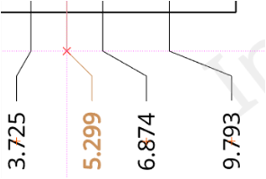
The red line and x, above, show the alignment of the red x jog point to the others
-
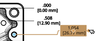
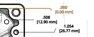
To change ordinate dimension style, open the Properties panel > Dimensions tab, and select ANSI or ISO from the Dimension style dropdown. ANSI ordinate dimensions display a leading line from the ordinate dimension. ISO ordinate dimensions display additional arrows that connect the increasing ordinate values from the origin point.
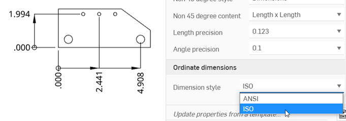
If you use an ANSI or ISO template when creating a new drawing, the ordinate dimension style defaults to ANSI or ISO, respectively.
-
Use the Drawing styles panel to style individual ordinate dimensions.
-
To replicate the ordinate dimension to another view in the drawing, see Views: Replicate annotations.