![]()
Shortcut: d
Available in: Drawing
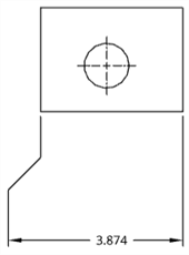
Place a dimension on any type of curve in a drawing.
When defining dimensions for a drawing, you will notice that orange snap points appear when you hover over a line or point. There are 5 types of snap points:
- Square snap points indicate end points
- Triangle snap points indicate midpoints
- Diamond snap points on a quad point of a circle or arc indicate one of the quadrants of the circle
- Circle snap points indicate an arc or circle's center; once a dimension snap point exists on a circle or arc's center, you can click and drag the point to a quadrant point.
Midpoints and quad points are disabled during dimensioning for ease of selecting appropriate dimension points. However, after a dimension has been placed, editing the dimension provides access to these midpoints and quad points.
Use keyboard shortcut Shift+q to quickly toggle on midpoints and quad points for the current command. Shift+q again to toggle them off.
Once the snap point is visible, the point has been snapped to and you can click. There is no need to click directly on the point once it is visible. While moving the mouse to place the dimension, you'll notice thin, dashed lines as the cursor passes near other entities. These are inferencing lines that you can align the dimension to; simply click when you see the line appear to align the dimension to that line.
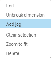
To clarify dimensions that are very close to each other, you can use jogged dimension extension lines. To add a jog to an extension line, right-click on the extension line to open the context menu, then click Add jog:
By default, the jog will appear at the midpoint of the extension line. Hover over dimension lines to highlight the snap points, then click and drag the snap points on the jogged extension line to position them to your preference:
You can dimension to hidden lines (after using the Show hidden lines command).
Editing the value of a dimension causes it to be converted to an Overridden dimension. See Troubleshooting dimensions.
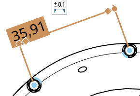
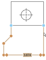
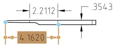
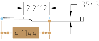
Once a dimension is created, hover over it to see which entities are involved in the dimension. The entities turn blue upon hover:
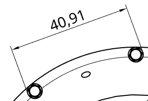
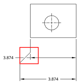
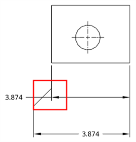
You can edit grip points of an existing dimension, if necessary. Click and drag any grip point to another edge, point, arc, circle, or circle center. Associations are maintained on other grip points. For example, in the illustrations below, the right grip point of the dimension is dragged from the point to the edge:
You can drag the dimension text simply by clicking and dragging. There is no need for a grip point on the text.
When an edge is selected, click again (even while dimensioning) to deselect it and select a different edge.
You can change the way intersecting dimension lines are displayed: as broken where they intersect or as unbroken where they intersect.
Right-click on the dimension and select Break dimension or Unbreak dimension from the context menu. Only one of the intersecting lines may be broken.
Broken dimension
Unbroken dimension
You can customize the appearance of a selected dimension (both driving and driven) with the Dimension palette. Selecting a dimension causes the dimension palette icon to appear.
- With no tool selected, select the dimension.
-
The Dimension palette icon appears
 .
.
- Hover over the icon to open the palette. (You can also double-click the dimension to open the palette).
- Set the following options in the palette. Some options may not appear in the palette, depending on the dimension type and other selected options.
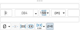
- Above text - Enter the text or symbol to appear above the dimension value.
- Prefix text
- Enter the text to appear as a prefix to the dimension value.
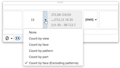
- Count type - Use the dropdown to select a count type for the dimension.
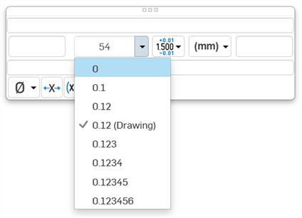
- Precision
- Select the depth of unit precision (zero to 8 decimal places).
Precision defined on a drawing dimension may be linked to the Properties panel through this Dimension palette by selecting the tolerance with “(Drawing)” beside it. Whenever the Properties panel tolerance precisions are updated, any dimension with the “(Drawing)” tolerance selected will also be updated. You can choose to link these properties (and unlink them) on a dimension-by-dimension basis.
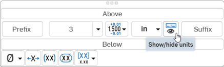
- Dimension units
- Select the units of your choice. The currently selected unit is displayed in the dropdown label:
Choose from: Millimeters, Millimeters (Drawing), Centimeters, Meters, Inches, Inches fractional, Feet and inches, Feet, or Yards. This selection overrides the units for that dimension. If you later change the drawing units, the units for the dimension are not overridden. You can change the units back to (Drawing) if you want to inherit the drawing properties again.
When you choose units, you set two properties in the drawing or on a dimension - the Units property and the Fractional display property.
- Drawing units are managed separately from Workspace units for Part Studios and assemblies
- Feet and Inches is only available in drawings; it is not available for workspace units.
- Toggle the Show/Hide units button as to display or hide the dimension units.
 .
.
- Suffix text - Enter the text to appear as a suffix to the dimension value.
- Below text - Enter the text or symbol to appear below the dimension value.
- Symbol dropdown
- Select a symbol to insert from the dropdown:
Symbol Name Shortcut ° Degree %%d ⌀ Diameter %%c ℄ Centerline ⌵ Countersink ↧ Depth ⌴ Counterbore □ Square ⌒ Arc length ± Plus/Minus %%p Ⓤ Unequally disposed profile Ⓘ Independency 
Continuous feature 
Spot face ▷ Translation - Inspection dimension - Toggle to add or remove an oval frame around the dimension to indicate this is an inspection dimension.
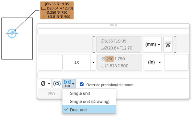
- Dual dimension
- Toggle to specify whether to have a single unit dimension, single unit as specified for the drawing properties, or a dual unit dimension:
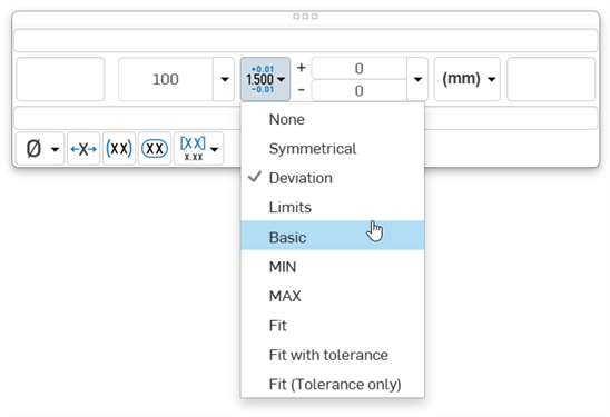
- Tolerance
- Select None, Symmetrical, Deviation, Limits, Basic, MIN, MAX, Fit, Fit with tolerance, or Fit (Tolerance only).
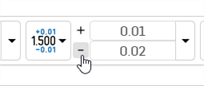
- Set the upper and lower tolerance (available for Symmetrical, Deviation, or Limits)
Optionally, to set a Deviation or Limits tolerance to plus/plus (+/+) or minus/minus (-/-), click the plus (+) or minus (-) button, as required:
- Set the Fit type, Shaft class, Hole class, and Fit standard (available for Fit, Fit with tolerance, or Fit (Tolerance only))
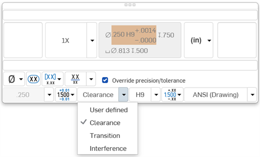
- Set the precision depth of the Fit tolerance units, from 0 to 8 decimal places (available for Fit with tolerance or Fit (Tolerance only))
- Set the upper and lower tolerance (available for Symmetrical, Deviation, or Limits)
- Reset text position - Toggle to reset the text to the previous location.
- Parentheses - Toggle to add or remove parenthesis around the dimension field.
- Toggle hole class visibility - (Available for Fit and Fit with tolerance options) Use this to show or hide the hole class in the dimension. When shown, select one of the following options:
- Stacked without line
- Stacked diagonally
- Stacked with line
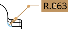
- Toggle Radius/Diameter dimension - Use this to change a radial dimension to diameter or vice versa.
You are also able to copy/paste into all text boxes, in dimensions and notes as well.
After picking two entities the dimension is drawn in a preview mode to allow final placement:
- Dragging the text around during preview allows for the text to move outside of the extension lines, and also switch between horizontal, vertical, and aligned measurement modes:
- Dragging the text away from the two chosen snap points up or down the drawing creates a horizontal dimension line:
- Dragging the text away from the two chosen snap points toward the side of the drawing creates a vertical dimension line:
- Dragging the text away in a direction perpendicular to a line through the two chosen snap points creates a dimension line parallel to the two chosen snap points:
- Horizontal and vertical projected snaps are also available during text placement. This allows for lining dimensions up with existing text/dimensions and other locations on the drawing:
Hover over a marker to wake up alignment. This is available in Preview mode only. Pass over other drawing entities to wake up alignment as well, like other views’ entities.
When the dimension tool is selected, you can move the cursor over an edge representing a circular edge to 'wake up' the center mark. Once visible, this mark remains visible.
Upon moving the cursor over an edge, an orange circular snap point appears, with the vertical center marker:
After hover, the orange snap point disappears but the marker remains:
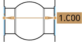
Change the position of dimension arrows. Use on any dimensions that display arrows or ticks.
When you select dimensions, a node displays near dimension arrows or ticks. Clicking a node flips the arrows of the dimension.
To flip dimension arrows:
- In the graphics area, select the dimension to change.
- Drag the value to the new position (the arrows change accordingly).
Use the right-mouse click to open a context menu on any dimension to access a list of command options for that dimension. These command options are listed below. Not all the commands listed here are available for every type of dimension.
-
Edit - Opens the dimension palette to edit the dimension.
-
Paste - Pastes the dimensions along with the view into the current location.
-
Clear selection - Deselects the selected dimension(s).
-
Zoom to fit - Zooms the entire Drawing into view.
-
Delete - Deletes the selected dimension(s).
Some issues that you may experience include:
- Dangling dimensions - A dimension with broken associativity, displayed in red. Drag the dimension snap point to re-associate to geometry. See Dangling entities for more information.
- Overridden dimension
- A dimension with the text value converted into a non-associative annotation. The text of an overridden dimension is always underlined. Editing the dimension value of a dimension causes it to be converted into an overridden dimension, as such:
- When a dimension is overridden, you can still edit the other fields in the dimension panel.
- You have the ability to restore an overridden dimension back to an associative dimension by deleting the characters in the dimension value field and exiting the panel.
- Underlined dimension values on an engineering drawing indicate the value is not to scale.