 Broken-Out Section View
![]()
![]()
![]()
Available in: Drawing
Create a broken-out section view to cut away a portion of the model in a drawing view by defining a closed profile with the Spline tool.
- Click
 .
.
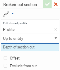
- Use the Spline tool to define a closed profile for the view.
Use the Spline point tool to add points with which to edit the spline.
- Select an end type, either Blind to a specified depth, or Up to entity (and select the point or edge on another view).
- Optionally select Offset to specify a distance by which to offset the cut.
-
Optionally, select Exclude from cut (Assembly views only) to select parts to not include in the cut:
-
Place the section cut line.
-
Check Exclude from cut in the dialog.
-
Click any additional parts to exclude in the drawing.
-
-
Click
 .
.
You can also double-click on the view to open the View properties dialog. Right-click and select Edit section to re-open the dialog and edit the specifications of the view (or Remove section to delete the broken-out section from the drawing).
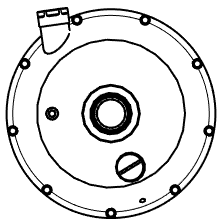
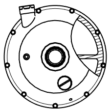
A view before the broken-out view is applied (left), and after the broken-out view is created (right)
Note that, the depth point (defined by the End type, described above) has an association back to the model. Therefore, if the model is modified resulting in a change of the depth point, the spline and depth point for the broken-out section will update with the update of the drawing. However in some cases the update may result in an error. The broken-out spline will be displayed in red; If a problem occurs, redefine the depth point to fix the issue.
This table illustrates the types of views from which the Broken-out section view can be created:
| Broken-out section view | |
| Can be created from: | Cannot be created from: |
|
Projected views Auxiliary views Break views Broken-out section views Crop views Views with other broken-out sections
|
Section views Detail views Aligned section views |