 Drawing Properties - Views
![]()
Available in: Drawing
Edit the current drawing's projection angle, the color and thickness of your drawing's visible edges, tangent edges, hidden edges, cutting lines, arrowheads, view labels and more.
To access View properties, click the Views icon (![]() ) at the top of the Drawing properties toolbar.
) at the top of the Drawing properties toolbar.
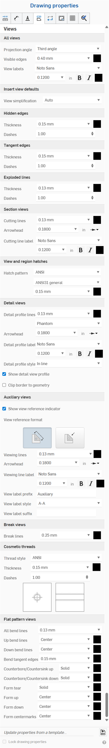
Properties that are common to all drawing views are explained below. Any properties specific to a view type are explained under that subheading, following this section.
- Line - Choose a line style, thickness, and color.
- Arrowhead - Choose an arrowhead size and style.
- Labels - Choose a font, font size, formatting, and color.
- Color
- To edit colors for any annotation entity, click the corresponding color block to access the color dialog:
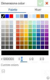
- Select Palette to choose a color or enter a hex or RGB codes. Use the Mixer panel to drag to a general color area and then enter a specific hex or RGB code.
On either the Palette or Mixer panels you can click the plus sign under Custom colors to save the currently specified color value as a custom color for later use.
Specify defaults here for all view types: Section views, Detail views, Break views, and Flat pattern views:
- Projection angle - Specify which projection to use
- Visible edges - Specify the thickness and color of lines representing visible edges
- View labels - Specify the font, size, font treatment and color of all view labels
Define default view styles upon inserting new views into drawings.
-
View simplification - Simplify the geometry shown in the drawing by setting a threshold below which features will be hidden. Choose from the following options:
- None - No simplification setting is applied.
-
Auto - Default. Finds the best view simplification settings based on the geometry of the part and automatically uses those settings to display the part or assembly.
-
Absolute - Enter a number in the length units of the drawing to indicate that any feature smaller than the value will be simplified within the view. If whole parts are smaller than the threshold value, those parts will be missing from the view. This is useful for removing excessive details not needed for drawing purposes (for example, a large number of very small features or components).
-
Ratio to studio - Enter a percentage of the size of the Part Studio or Assembly below which the feature will be simplified within the view. If whole parts are smaller than the threshold value, those parts will be missing from the view. This is useful for removing excessive details not needed for drawing purposes (for example, a large number of very small features or components).
-
Ratio to part - Enter a percentage of the size of the part below which the feature will be simplified within the view. This setting aims to preserve parts in a view, while simplifying the detail within those parts. This is useful if you intend to ensure all the parts are present to facilitate detailing actions, such as placing callouts.
-
Auto centermarks (Parts) - Choose to toggle on or off. (Applicable for parts only.)
-
Auto centerlines (Parts) - Choose to toggle on or off. (Applicable for parts only.)
-
Hidden lines - Choose Hidden or Shown lines.
-
Threads (Parts) - Choose Hidden or Shown threads. (Applicable for parts only.)
-
Bend lines (Parts) - Choose to toggle on or off. (Applicable for parts only.)
-
Bend notes (Parts) - Choose to toggle on or off. (This option is only available if the Bend lines option is toggled on. Applicable for parts only.)
-
Tangent edges - Choose Hidden, Solid, or Phantom tangent edges.
-
Scale label - Choose to toggle on or off.
Views created from other views (section views, detail views, etc.) will automatically adopt the same Insert view defaults as the parent view.
Specify the thickness and color of lines representing hidden edges, as well as the spacing of the dashes.
Specify the thickness and color of lines representing tangent edges, as well as the spacing of the dashes.
Specify the thickness and color of the exploded lines of the exploded view, as well as the spacing of the dashes.
Specify defaults here for:
- Hatch pattern - Specify the default type and pattern for the hatch marks
- Hatches - Specify the default line size and color for hatch marks
- Cutting lines - Specify the default line size and color for cutting lines
- Arrowhead - Specify the default size and arrowhead type (filled, unfilled, or open)
- Cutting line label - Specify the font, size, font treatment and color of all cutting line labels
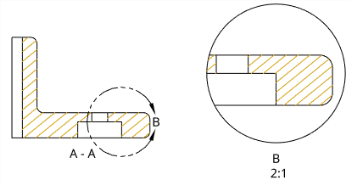
In the illustration above, the hatches of the section view were changed to a gold color (which is propagated to the detail view as well) and the arrowhead on the cutting line was increased in size
Specify details here for:
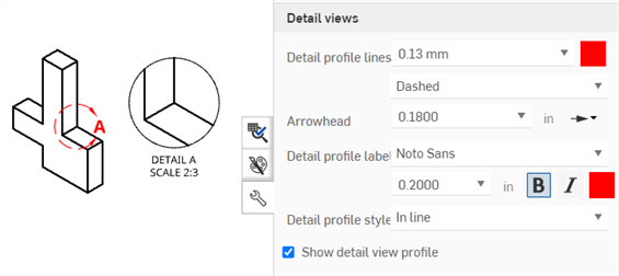
- Detail profile lines - Specify the default line size, color, and style (Phantom, Dashed, or Solid) of the detail profile lines.
- Arrowhead - Specify the default size and arrowhead type (filled, unfilled, or open).
- Detail profile label - Specify the font, font size, style, and color of all detail profile labels.
- Detail profile style - Select In line, Connected, or Leader.
- Detail view profile - Deselect the check box to remove the outline surrounding the Detail view.
- Show detail view profile - Displays the detail view profile.
- Clip border to geometry - By default, the detail view border is displayed. Enabling this option displays the detail view geometry only, without a border.
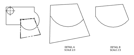
Original Front view (left), Detail A with Clip border to geometry disabled (middle); Detail B with Clip border to geometry enabled (right).
Specify details here for:
- Show view reference indicator - Show/hide the view reference indicator.
- View reference format - Click the format image to switch the view reference indicator format between line style and arrow style.
- Viewing lines - Specify the default view reference indicator line thickness and color.
- Arrowhead - Specify the default size and arrowhead type (filled, unfilled, or open).
- Viewing line label - Specify the font, size, font treatment and color of all viewing line labels.
- View label prefix - Enter a prefix to display before the view label.
- View label style - Select between A-A and A.
- View label suffix - Enter a suffix to display after the view label.
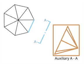
An Auxiliary view shown in the brown bounding square, the view plane and reference indicator shown in blue, and the label shown in black.
You can also create dimensions or Line to line angular dimensions using the Auxiliary view arrow style as a reference point. Once the Auxiliary view is created, open the Properties panel > Views > Auxiliary views, and select Arrow style as the View reference format. You can then create the angular dimension using the Dimension tool.
Specify the default line thickness and color for break lines.
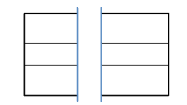
In the illustration above, the break line thickness is 0.50mm and the color is blue
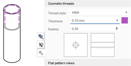
Specify the thread style, thickness, and color for internal and external threads. You can also specify the dash length scale for ANSI threads.
For drawings of sheet metal flat patterns, specify the following:
-
All bend lines - Adjust the thickness of all bend lines
-
Up bend lines - Adjust the style (Solid, Dashed, or Center (default)) and color of the up bend lines.
-
Down bend lines - Adjust the style (Solid, Dashed, or Center (default)) and color of the down bend lines.
-
Bend tangent edges - Adjust the thickness and color of the bend tangent edges.
-
Counterbore/Countersink up - Adjust the style (Solid (default), Dashed, or Center) and color of the Counterbore/Countersink up lines.
-
Counterbore/Countersink down - Adjust the style (Solid (default), Dashed, or Center) and color of the Counterbore/Countersink down lines.
-
Form tear - Adjust the style (Solid (default), Dashed, or Center) and color of the Form tear lines.
-
Form up - Adjust the style (Solid, Dashed, or Center (default)) and color of the Form up lines.
-
Form down - Adjust the style (Solid, Dashed, or Center (default)) and color of the Form down lines.
-
Form centermarks - Adjust the style (Solid (default), Dashed, or Center) and color of the Form centermarks.
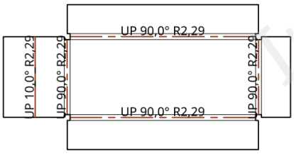
In the illustration above, all bend lines have a value of 0.50mm and the up bend lines have a red color specified