 鑽孔表格
鑽孔表格
![]()
插入一個視圖或共同單一零件 (不是整個 Part Studio) 多個視圖的鑽孔表格。如同格式化其他表格一樣建立鑽孔表格的格式,將滑鼠移動至表格中的列上暫留,以查看工程圖中的交叉強調顯示。
本主題說明工程圖中的鑽孔表格。請參考 Part Studio 鑽孔表格的主題來獲得在 Part Studio 中使用鑽孔表格的資訊。
- 按一下
 。
。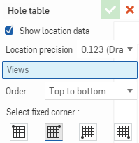
- 核取方塊以指定要在選取的視圖中顯示位置資料。
- 指出位置座標的精度。
- 選擇一個視圖來將其中的鑽孔登錄於表格中。若要選擇多個視圖,在「視圖」欄位中再按一下,然後選擇另一個視圖。重複此步驟來選擇所有需要的視圖。
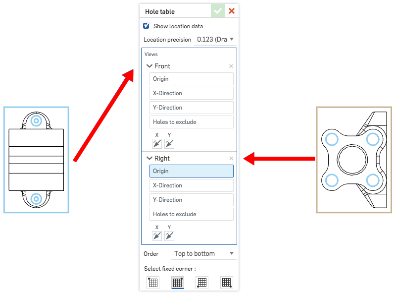
當您選擇工具時,會出現表格的預設,且當您選擇要出現在表格中視圖時,系統會工具會移入。
-
選擇要從該處定位鑽孔的原點。
- 藉由點按工程圖中的邊線來為鑽孔位置選擇 X 或 Y 軸。
- 選擇要從表格中排除的鑽孔 (在工程圖中點按這些鑽孔)。
- 指定在表格中列出鑽孔的順序,英文字母-數字 (由上至下或由下至上)。
僅當工程圖是由一個零件而非整個 Part Studio 組成時,才能夠選擇視圖。
- 選擇與表格角落相符的圖示以設定固定的角落。

在 Onshape 中預設的錨點是表格的右上角。
一旦點出現之後,則不需要在點上直接點按。在移動滑鼠來放置鑽孔表格的操作中,您會在游標經過靠近其他圖元時,看到細虛線的出現。這些是您可以用來對齊鑽孔表格的推斷線;當您看到推斷線出現時只要按一下即可將鑽孔表格與該線對齊。 - 在工程圖紙空間上按一下來放置鑽孔表格。

將滑鼠移動至表格中的列上暫留,以在工程圖中查看交叉強調顯示:
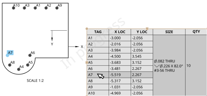
編輯鑽孔標記
在視圖中鑽孔的軸上按右鍵 (如下圖中強調顯示) 來存取相關的環境選單。視圖中鑽孔的環境選單為:
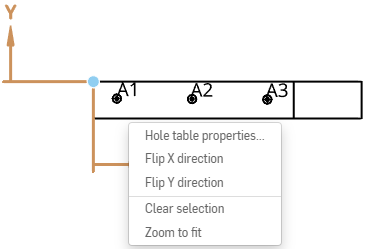
- 鑽孔表格屬性 - 開啟鑽孔表格的屬性面板。
- 反轉 X 方向 - 反轉 X 軸箭頭的方向。
- 反轉 Y 方向 - 反轉 Y 軸箭頭的方向。
- 清除選取項目 - 清除所選的項目。
- 縮放至適當比例 - 縮放工程圖以配合視窗大小。
編輯鑽孔表格
您可以用編輯工程圖中任何表格的類似方式來編輯鑽孔表格。按一下表格的邊框來選取整個表格;抓著任一角落抓點來移動表格,拖曳中間抓點之一來調整表格的大小。在表格上按右鍵來存取有下列指令的環境選單:
- 鑽孔表格屬性 - 開啟鑽孔表格的屬性面板。
- 分割上方/下方鑽孔表格 - 分割滑鼠游標所在列 (在按右鍵使用環境選單處)下方的鑽孔表格。這樣會將表格分割成兩個表格,然後您可選擇其中一個表格並按右鍵使用環境選單中的移至圖頁來將該表格移動至工程圖中的另一圖頁內。
- 移動至 - 邊框框架、邊框區域、標題區塊、工程圖
- 帶回前方 - 將所選表格帶回顯示的前端中
- 送至後方 - 將所選表格送至顯示的背景後
- 移至圖頁 - 將表格 (或分割的表格) 移動至工程圖中另一個現有圖頁上。
- 清除選取項目 - 取消選擇目前選取的表格
- 縮放至適當比例 - 縮放工程圖以配合視窗大小
- 刪除 - 刪除目前選取的表格
格式化表格
-
您可以在表格上按右鍵再選擇 [大小],然後選擇是要將欄或是列的大小調整為均等。點按並拖曳一個水平或垂直的中間點來調整表格大小。

-
若要調整儲存格雙邊的列與欄大小而不調整表格大小,請將游標移動至儲存格上方或右側邊上暫留, 當游標變為雙向箭號時,按一下並拖曳邊線至新的位置放置。若僅要調整所選儲存格的列或欄大小,然後重設整個表格的大小,請將游標移動至儲存格下方或左側邊上暫留,當游標變為雙向箭號時,按一下並拖曳邊線至新的位置放置。
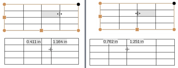
重新調整分隔線兩側的欄大小而不調整表格的大小 (左側的兩個圖片);僅調整所選儲存格的欄大小,並相對應地調整整個表格的大小 (右側的兩個圖片)。
-
若要使用數值重新調整欄寬或列高,請選擇一個儲存格並按右鍵,然後選擇 [重新調整大小] 來開啟「重新調整大小」對話方塊。輸入新的「欄寬」或「列高」數值。
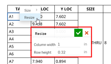
- 您可以在表格的中間點上連按兩下來自動調整為配合表格內容大小。
- Single-click in a table cell or row to activate the Cell formatting panel:
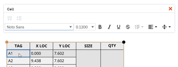
儲存格格式設定面板
在表格的儲存格中連按兩下以開啟儲存格格式設定面板:

![]() 欄大小均等 - 將所選欄大小調整至平均的寬度
欄大小均等 - 將所選欄大小調整至平均的寬度
![]() 列大小均等 - 將所選列大小調整至平均的高度
列大小均等 - 將所選列大小調整至平均的高度
當至少選擇了一個儲存格時,您可以從環境選單中存取這些指令:
在「註解」面板中提供的所有文字格式化指令也同時在儲存格格式設定面板中提供。
複製來自 Onshape 工程圖表格中的表格儲存格,然後將其以一個新的可編輯表格貼入至 Excel、Google 試算表、或 Onshape 工程圖中。
在 Google Chrome、Mozilla Firefox 與 Microsoft Edge 上支援將 Onshape 工程圖表格複製到 Excel 或 Google 試算表中。在 Safari 上是不支援的。由於平台的限制,複製文字可能會產生不同的結果。
-
開啟一個 Onshape 工程圖表格。
-
按一下並拖曳來選取要複製的儲存格。系統會以黃色的輪廓線來呈現選取的項目。
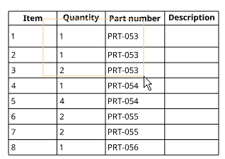
-
放開選取項目。系統會以藍色輪廓線圈出所選的儲存格。按下 ctrl+c 或按右鍵然後選擇複製。
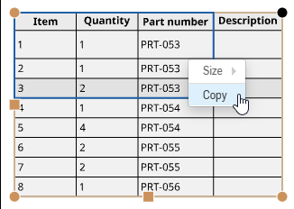
-
開啟您要貼入內容的工程圖或外部試算表。
-
在您要貼上表格的位置上按右鍵,然後選擇貼上 (或按下 ctrl+v):
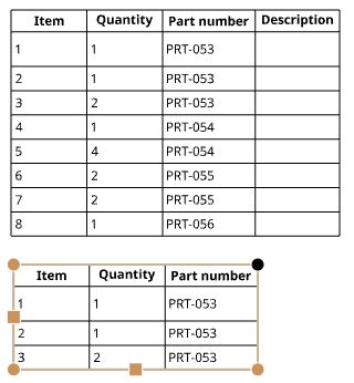
如果在 Mozilla Firefox 瀏覽器中使用 Onshape,請使用 ctrl+v 來貼上表格。並不支援使用環境選單中的「貼上」指令。
在表格上按右鍵,然後選擇 [刪除]。
選擇表格,然後按右鍵並選取 [鑽孔表格屬性] 來開啟該表格的「屬性」對話方塊:
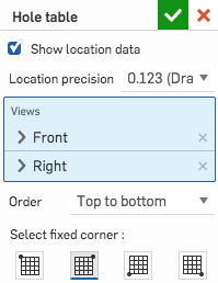
您可以指定是否要在工程視圖中顯示位置座標,以及是否要在表格中摺疊標記。
您也可以變更對鑽孔表格所做的其他指定,包括所選取的視圖,表格中標記的順序以及要固定的表格角落。
按一下核取記號來記錄您的編輯。