 拔模
拔模
![]()
![]()
![]()
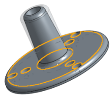
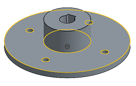
Apply a draft angle to one or more selected faces, or a parting line, in order to facilitate pulling a part from a mold. For information on analyzing a draft, see Draft analysis.
- 按一下
 並選擇 [中立面]。
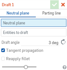
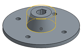
- With focus on the Neutral plane field in the dialog, click on the entity to act as the neutral plane. (You can select the face of the part or a Mate connector to act as a neutral plane.)
- 在要拔模的圖元欄位中按一下,然後選擇要套用拔模的所有面。
- 在數值欄位中指定拔模的角度。
- 指出是否要沿著相切面套用拔模;這樣拔模會套用至所有相切的面上。
請注意:沿相切面進行僅會選擇比拔模角度更陡的面。在所有的狀況中,會重新套用不是那麼陡的圓角。
- 選擇性的設定是否要「重新套用圓角」:會將陡的圓角面視為拔模面,而不是圓角面。通常而言在使用大拔模角度的情況下,這樣會產生不希望看到的幾何。在沒有核取「重新套用圓角」的情況下,會將陡的圓角面視為圓角並將其重新混合。這樣會產生圓柱面而非圓錐面,且通常會產生較理想的結果。
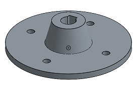
- 選擇性使用,可使用滑桿來視覺查看套用拔模之前和之後的差異。
- 按一下
 。
。
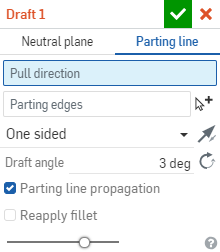
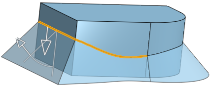
Drafting along a parting line requires an existing parting line along a face (or faces) before beginning the draft operation. Create a parting line using the Split tool and split a face (or faces), not a part. To create a draft, select the Draft command on the toolbar, then select the Parting line option. Click the Pull direction. This can be a part face or Mate connector (implicit or explicit). Next, select the line you created as the Parting edge. Choose if the draft is One sided, Symmetrical, or Two sided. Enter the Draft angle numerically in the Draft dialog, or edit the orange angle arrow directly in the graphics area. Click the Reverse icon to direct the draft inward. Check Parting line propagation to extend the draft along the entire parting line to tangential faces only. Check Reapply fillets to generate cones and preserve the parting line edges. When finished, click the green checkmark to accept the new draft.
沿分模線拔模在開始拔模之前需要有沿著一或數個面的現有分模線。請使用「分割」工具並分割面 (不是分割零件) 來建立分模線。
- 按一下 並選擇 [分模線]。
- With focus on the Pull direction field in the dialog, click on the face or Mate connector (implicit or explicit) of the part to act as a neutral plane, along the primary axis.
- 在分模邊線欄位中按一下,然後選擇您建立來用做分模線的直線。
核取沿分模線進行來將拔模僅沿著整個分模線行進至相切面。同時可以使用多重選取來選擇多條不論相切與否的線段。
- 選擇要套用拔模的分模邊:單邊、對稱或雙邊 (使用 [交換面] 箭頭
 來從一個面反轉至另一個相反面)。
 - 在數值欄位中指定拔模的角度。
- 選擇性的設定是否要重新套用圓角:會將陡的圓角面視為拔模面,而不是圓角面。這樣會產生圓錐並保留了分模線邊線。通常而言在使用大拔模角度的情況下,這樣會產生不希望看到的幾何。在沒有核取重新套用圓角的情況下,會將陡的圓角面視為圓角並將其重新混合。這樣會產生圓柱面而非圓錐面,並會修改分模線邉線且通常會產生較理想的結果。
- 選擇性使用,可使用滑桿來視覺查看套用拔模之前和之後的差異。
- 按一下 。
套用一個拔模角度至一或多個所選面,或是分模線上,以幫助零件從模具中脫出。
步驟
- 輕觸拔模工具。

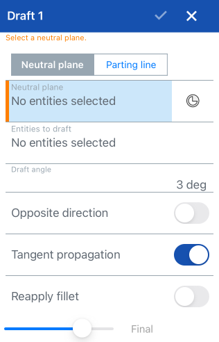
- Select a Neutral plane using a face or a Mate connector (along the primary axis).
- Tap the Mate point connector icon in order to select or create implicit Mate connectors.
- 選擇要拔模的圖元。
- 指定拔模角度。
- 選擇性地切換來將拔模轉至相反的方向。
- 選擇性地切換來使用沿相切面進行。
- 選擇性地切換來重新套用圓角。
請注意:
- 沿相切面進行僅會選擇比拔模角度更陡的面。
- 在切換關閉重新套用圓角的情況下:會將陡的圓角面視為拔模面,而不是圓角面。這樣會產生圓錐並保留了分模線邊線。通常而言在使用大拔模角度的情況下,這樣會產生不希望看到的幾何。
- 在所有的狀況中,會重新套用不是那麼陡的圓角。
- 輕觸核取記號。
套用一個拔模角度至一或多個所選面,或是分模線上,以幫助零件從模具中脫出。
步驟
- Tap Draft tool.
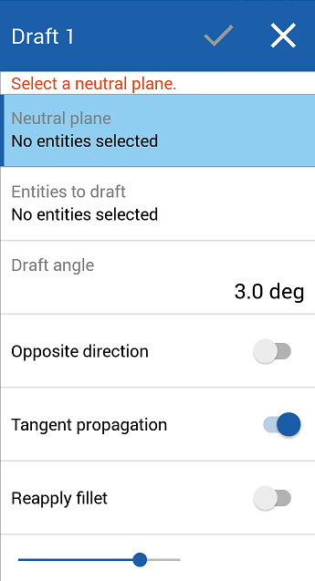
- Select a Neutral plane using a face or a Mate connector (along the primary axis).
- 選擇要拔模的圖元。
- 指定拔模角度。
- 選擇性地切換來將拔模轉至相反的方向。
- 選擇性地切換來使用沿相切面進行。
- 選擇性地切換來重新套用圓角。
請注意:
- 沿相切面進行僅會選擇比拔模角度更陡的面。
- 在切換關閉重新套用圓角的情況下:會將陡的圓角面視為拔模面,而不是圓角面。這樣會產生圓錐並保留了分模線邊線。通常而言在使用大拔模角度的情況下,這樣會產生不希望看到的幾何。
- 在所有的狀況中,會重新套用不是那麼陡的圓角。
- 輕觸核取記號。