組合件組態
組合件組態
![]()
在 Onshape 中不論您是否有 Part Studio 組態,您都可以在組合件內建立自己的組態。組態是各自獨立且互不影響的。
組合件組態與 Part Studio 組態運作機制相同,不同之處是在組合件中僅能設定結合 (不是結合連接器)、實例與複製排列。
當有多位使用者在同一文件上操作時,每個人可以看到自己所選的組態 (除了是以跟隨模式操作時,在此種情況下跟隨者會看到領導者選取的組態)。
若要進一步了解組合件組態,您可用自己的步調跟著 Assembly configurations (需要有 Onshape 帳戶) 的課程操作。
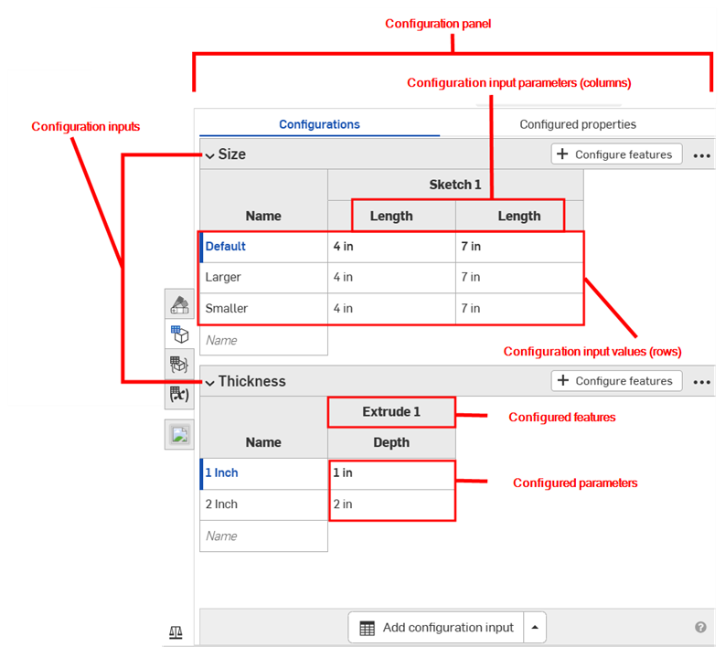
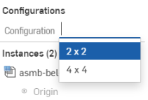
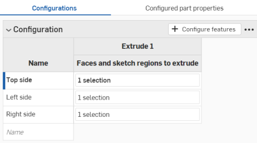
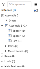
下方的範例顯示視窗右側有組合件的組態面板圖示,出現在紅色箭頭的右邊:
![]()
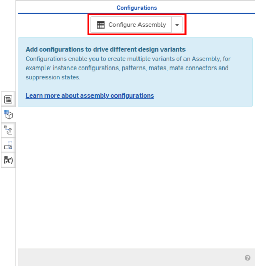
在工作區中有零件實例或組合件的情況下,開啟「組態」面板:
- 按一下圖形區域右側的
 (如上圖所示)
 -
「組態」面板開啟:
- 按一下
 :
: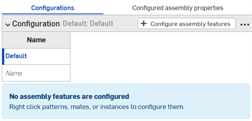
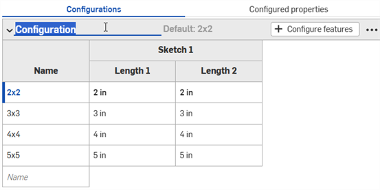
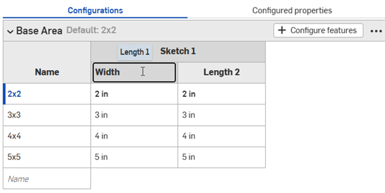
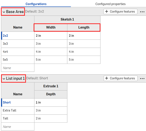
- 按一下第一個列來啟用,然後在「名稱」欄鍵入輸入項的名稱。例如,若要在一個零件上設定複製排列,您可以將列取名為 2x2 與 4x4。可以使用 Tab 鍵來在列之間移動。
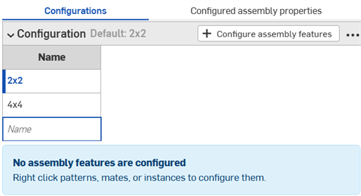
列左邊的藍條代表在組合件中目前選取的組態。
- 若要為指定的列設定輸入值,按一下
 。
。 - 選擇包含參數的結合、實例或複製排列 (在組合件清單中按一下該項目),然後在開啟的對話方塊中選擇參數 (在下圖中以紅色輪廓線框出)。接下來會以黃色虛線框出參數,並在組態中為該輸入項建立一個新的欄 (如下圖中紅色箭頭左側的「組態」面板所示)。
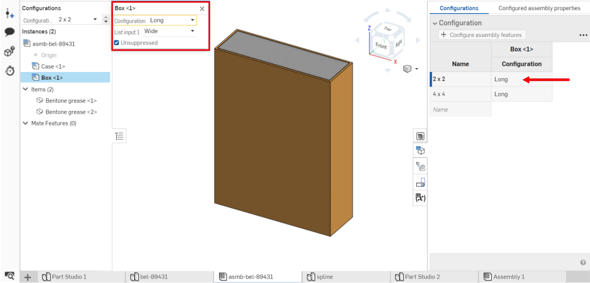
預設的欄位名稱會是所選取圖元的名稱 (最上層的標題) 加上欄位名稱 (次級階層標題)。在這個範例中 Box <1> 是選取的圖元,使用者已將欄位名稱變更為 2 x 2 與 Long。
- 編輯已組態參數:
- 如果輸入項是一個已經輸入的值,在表格中按一下列來輸入新的值。
- 如果輸入項在對話方塊中是一個選取項目,連按兩下表格中的列來開啟特徵對話方塊。
在特徵對話方塊中適當的欄位會以藍色強調顯示。在模型或實例清單中為這個輸入項做出選擇。
- 在完成組態的定義後,按一下視窗上方橘色訊息中的完成按鈕,或關閉對話方塊。
- 為每個列重複步驟 6 到步驟 8。
- 重複步驟 5 到步驟 8 來將另一個特徵加入到組態中。
- 若要在模型上測試您的輸入,請於「特徵」清單中的組態之下,使用下拉箭頭來從功能表中選擇:
根據預設,「組態」左側的插入符號是展開的 (上圖中紅色箭頭的右邊),當您完成面板該部分的操作時,按一下插入符號來摺疊該部分。
將游標移動到特徵對話方塊中的欄位上暫留,查看可以組態那些特徵。當您移動游標於特徵上暫留時,可供組態使用的特徵會以黃色強調顯示。
模型應會相對應地更新。如果沒有,請檢查模型確定有正確傳達設計意圖,並已為組態定義做出正確的選擇。
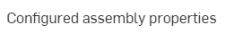
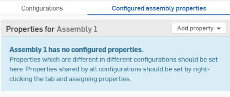
Onshape 同時提供可直接在「組態」面板中為您之前已定義的組態輸入項設定組合件屬性的機制。可組態的屬性包括:名稱、說明、零件編號、修訂版、廠商、專案、產品線、標題 1、標題 2、標題 3,非修訂版管理的與從所有 BOM 中排除。
組態設定組合件屬性:
- 在「組態」面板中有現存的組態輸入項的情況下,按一下面板最上方的
 (在下圖中以藍色輪廓線框出):
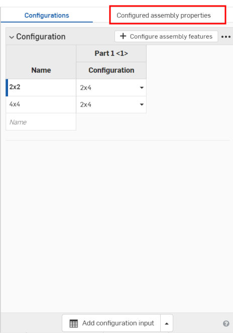
- 按一下
 。
。 - 選擇您要組態的組合件屬性 (清單中包括屬性) (這個範例使用的是「專案」)。
會建立一個表格,其中第一個欄有之前所選組態的輸入項,屬性則在第二個欄中:
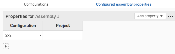
- 在「組態」欄中使用下拉箭頭來從組態選項清單中選擇。
- 在「專案」欄 (專案屬性) 中輸入名稱。
- 若要為另一個組態選項加入更多的零件屬性,按一下
 。
。 - 從第一欄中選擇一個新的組態選項。
- 在「專案」欄 (專案屬性) 中輸入名稱。
- 根據需要為所需的組態選項設定屬性。
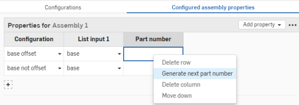
在組態設定零件編號屬性時,若自動產生零件編號選項是開啟的,您可以按滑鼠右鍵並選擇 [產生新零件編號] (透過您 Professional Company 設定 > 編號方案 或 Enterprise 設定 > 編號方案):
若要變更組態的名稱,請點按組態名稱並輸入新的名稱。在編輯方塊外按一下來儲存變更。
如果在表格中有任何屬性是設定為唯讀的,則您無法刪除表格,將屬性加入至表格中,或移除唯讀的屬性欄。仍可修改可編輯屬性的儲存格值。將唯讀屬性重設為可編輯的以修改表格。
由組合件鏡射衍生而來組合件中的組態表格與輸入項會是唯檢視的,並會從來源組合件中參考它們。必須在來源的組合件分頁中才能編輯這些組態表格與輸入項。
在本節中的範例顯示一個已組態的 Part Studio;可用功能與在已組態組合件中的操作完全相同。
若要重新命名組態輸入項或輸入項參數 (欄),將游標移動至目前名稱上暫留以顯示 I 游標。按一下來選擇目前的文字,輸入新的文字,然後按下 Enter 鍵。
重新命名組態
僅能為草圖特徵重新命名組態輸入項參數 (欄)。
也可以透過環境選單重新命名組態輸入項。請見下方環境選單的部分。
Configuration context menus
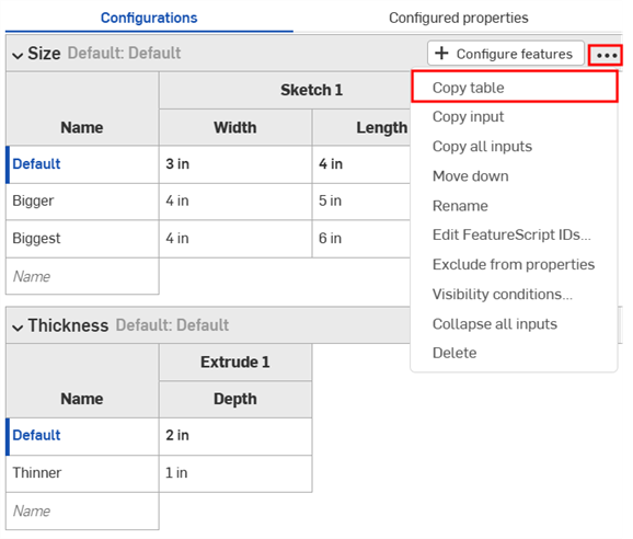
To make adjustments to a configuration input, click three-dot button ![]() . The options on the context menu will vary depending on if you're configuring a Part Studio, Assembly, or Variable Studio:
. The options on the context menu will vary depending on if you're configuring a Part Studio, Assembly, or Variable Studio:
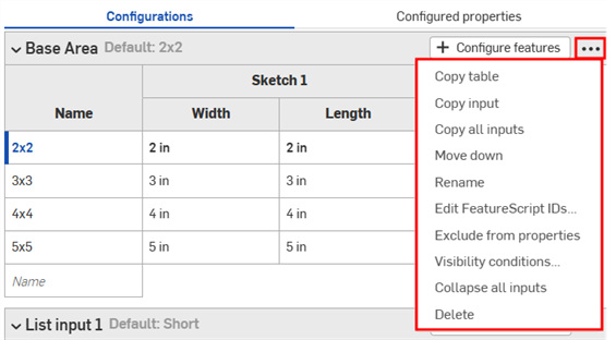
- 複製表格 - 複製整個組態輸入項,然後您可以將其貼入試算表中來保存記錄或編輯。您也可以從試算表中將其貼回至組態輸入項。請參考本頁中複製與貼上輸入項值及參數的部分。
- 複製輸入項 - 複製輸入項和跟值 (列),然後您可以將其貼入至另一 Part Studio 或組合件的「組態」面板中,然後使用「複製表格」的指令來加入參數。請參考本頁中複製與貼上輸入項的部分。
- 複製所有輸入項 - 複製在「組態」面板中的所有輸入項與值 (列),然後您可以將其貼入至另一 Part Studio 或組合件的「組態」面板中,然後使用「複製表格」的指令來加入參數。請參考本頁中複製與貼上輸入項的部分。
- 上移/下移 - 重新調整「組態」面板中輸入項的順序。您也可以點按並拖曳輸入項來重新調整其順序。
- 重新命名 - 重新命名組態輸入項。您也可以如上方重新命名組態部分所述的來重新命名輸入項。
- Edit FeatureScript IDs - (Parts and Part Studios only) This dialog will change the internal FeatureScript identifiers of the configuration input. Click inside the dialog boxes to change IDs. When finished, select Break reference and change IDs in the lower right corner.
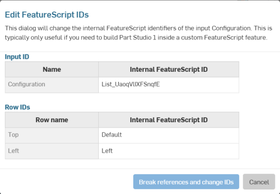
這個對話方塊通常是在需要於自訂 FeatureScript 特徵內部建立 Part Studio 時才有用。
- Exclude from properties - (Parts and Part Studios only). See Configurations: Excluding configurations from affecting properties.
- 摺疊/展開所有輸入項 - 摺疊或展開「組態」面板中的所有組態輸入項。
- 顯示情形條件 - 請參考本頁中設定顯示情形條件的部分。
- 刪除 - 選擇這個動作來立即刪除組態輸入項;系統不會發出任何警告。
對於所有表格,請使用環境選單 (按滑鼠右鍵) 進行對列或欄的操作:
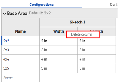
欄環境選單
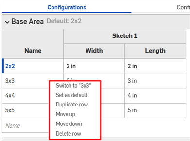
列環境選單
- 切換至 - 當在非目前所選輸入項的列上按右鍵時,功能表項目會顯示開端為切換至不同輸入項。
- 設為預設 - 如果一個列目前不是預設的輸入值,將其設定為新個預設。目前的預設會顯示在輸入項的名稱旁。
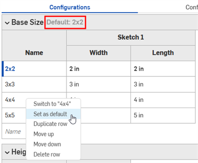
- 複製列 - 建立重複的列;在準備要將新輸入項貼至這個表格時特別有用。詳細資訊請參考本頁中組態輸入項表格中的表格複製與貼上的部分。
- 上移/下移 - 將所選列向上或向下移動一列。您也可以點按並拖曳來重新調整列的順序。
- 重新命名 - 重新命名輸入項。
- 刪除欄/列 - 刪除所選的欄或列。
您可以按一下並拖曳表格中個別的欄邊線以調整欄的大小;在欄標籤堆疊的情況下,按一下並拖曳底部的標籤 (上方圖例中藍色箭頭所指)。
在本節中的範例顯示一個已組態的 Part Studio;可用功能與在已組態組合件中的操作完全相同。
您可以在 Part Studio、組合件、與 Variable Studios 之間複製及貼上組態輸入項。這樣使得在設計之間分享組態更為快速與容易。
-
在 Part Studio、組合件、或 Variable Studio 中開啟包含了要複製輸入項的「組態」面板。
-
按一下輸入項的三點功能表,然後選擇複製輸入項或複製所有輸入項。
![組態輸入項三點功能表,其中強調顯示 [複製輸入項] 與 [複製所有輸入項]](Resources/Images/feature-tools/config-copy-inputs-02.png)
-
在分頁中開啟「組態」面板來貼上輸入項。
-
按一下「組態 Part Studio/組合件/Variable Studio」旁的箭頭,然後選擇 貼上輸入項。
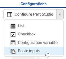
輸入項即被插入至「組態」面板中。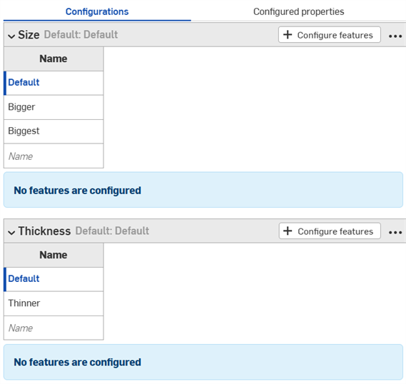
-
從新分頁中選擇要組態的參數。繼續閱讀以了解如何將輸入項的值與參數複製到輸入項表格中。
注意:
- 您可以複製與貼上組態輸入項:在 Part Studio、組合件與 Variable Studios 之間;在同一文件中;以及在不同文件之間。
- 所有的名稱、顯示情形條件、FeatureScript ID、以及變數定義都會隨輸入項一起複製。
- 經複製的輸入項直到使用者登出之前都可使用。
- 系統不會維持複製輸入項與貼上輸入項之間的參考;一旦貼上之後,對原始組態的變更不會反映在貼上的輸入項中。
- 如果目標組態並沒有計算顯示情形所需要的所有輸入項,系統會自動修復 (移除) 貼上的顯示情形條件。
- 系統不會貼上有相同內部 FeatureScript ID 的組態輸入項。要解決這個問題,您可以刪除有相同內部 FeatureScript ID 的組態然後再次貼上。
您可以複製與貼入組態中或反向操作,以幫助輸入或編輯值。
複製值與參數:
- 開啟「組態」面板右上角的
 功能表。
功能表。 - 選擇複製表格:
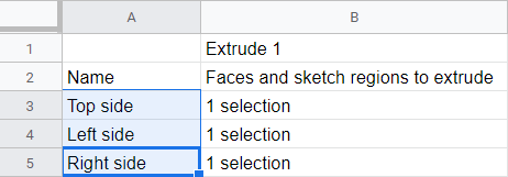
- 複製表格之後,您可以將其貼入試算表中:
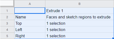
請注意,欄名稱會與表格一起貼入 (如上所示)。您現在可以編輯表格,然後將其複製/貼回 Onshape 中:
- 僅選擇內有資料的列與欄 (不是欄名稱或標題),如下方藍色部分所示:
如果需要,您也可以使用額外的空白列來加長表格。只需要在選取複製指令時,將額外的列包含在試算表中。
- 送出複製的指令。
- 在 Onshape 組態表格中,按一下表格最左上方的儲存格。
- 送出鍵盤的貼上指令:
Onshape 會自動以所複製的資料取代組態輸入項表格列與欄內的任何資料。Onshape 同時會自動包括各個輸入項的預設單位。
注意,如果從試算表中複製的列數多於 Onshape 組態輸入項表格中的列數,則在貼上的操作中會包括多的欄。Onshape 會在操作的過程中建立列。
不過,如果從試算表中複製的欄數多於 Onshape 組態輸入項表格中的欄數,則在貼上的操作中不會包括多的欄。Onshape 不會在操作的過程中建立欄位。不過您可以在貼上之前於組態表格中建立額外的欄 (參數)。
在本節中的範例顯示一個已組態的 Part Studio;可用功能與在已組態組合件中的操作完全相同。
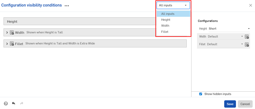
組態顯示情形條件對話方塊可讓您在組態中加入邏輯,以控制何時可以使用某些輸入項與選項。
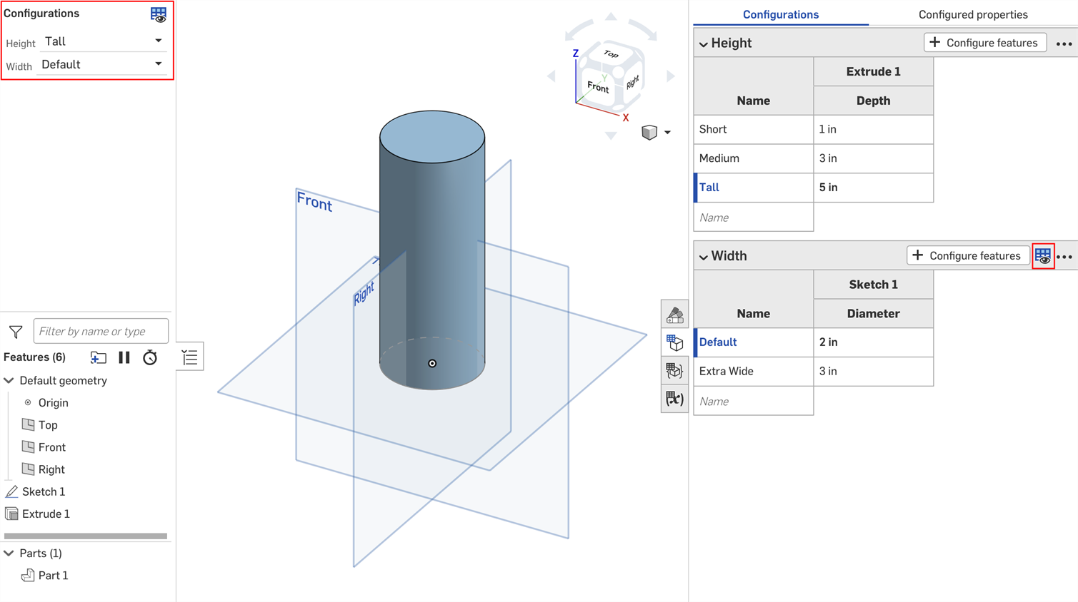
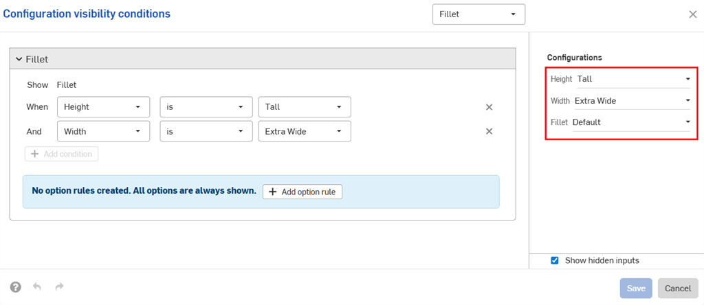
請考慮一個有高度 (Height) 與寬度 (Width) 這兩個輸入項的零件。
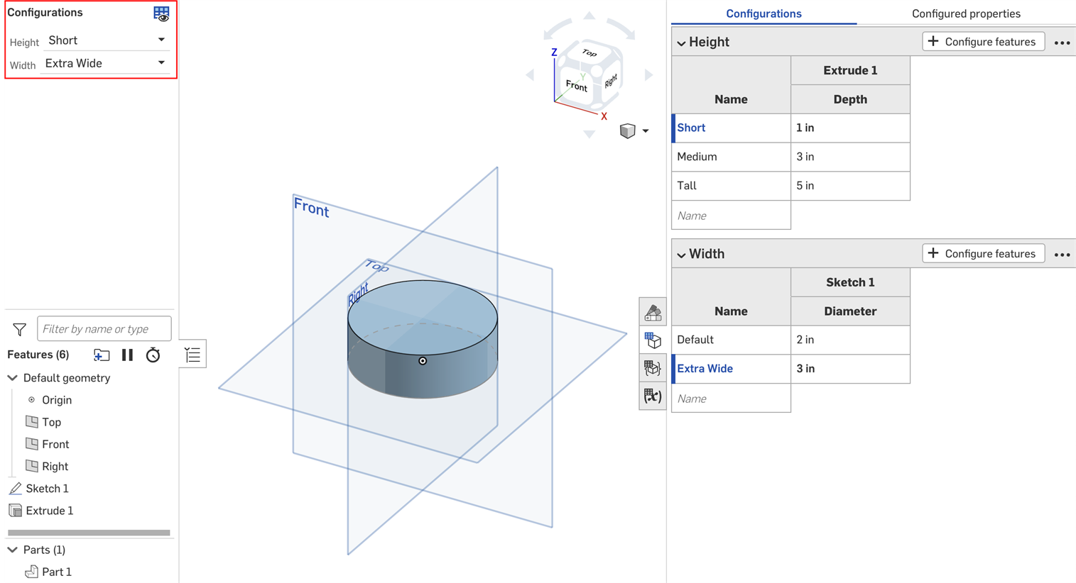
根據預設,任何高度可以有任何的寬度。但假設「Extra Wide」寬度僅能用於「Tall」的高度中。在這樣的情況下,我們可以設定「Width」輸入項會顯示的條件為何。
- 在組態面板中,按一下輸入項的三點按鈕,然後從功能表中選擇顯示情形條件。
組態顯示情形條件對話方塊開啟。右側的面板顯示目前所選組態的預覽。您可以直接在這個面板中變更所選的選項來預覽您的設定。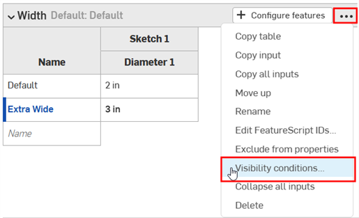
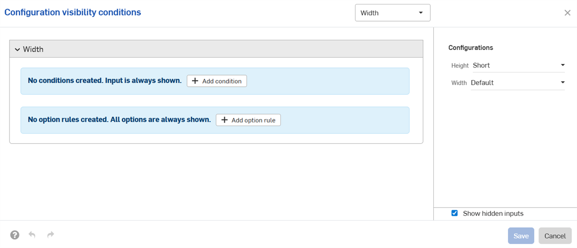
- 按一下加入條件。
- 按一下第一個下拉清單,然後選擇控制這個輸入項顯示情形的輸入項。在這個範例中將選擇「Height」輸入項。
- 在第二個下拉清單中,選擇是來選擇特定的選項,或選擇是介於來選擇選項的範圍:
- 是:按一下出現的第三個下拉清單,然後選擇對該輸入項允許的選項。
- 是介於:按一下第三個下拉清單,然後選擇範圍中允許的第一個選項。按一下第四個下拉清單,然後選擇範圍中允許的最後一個選項。
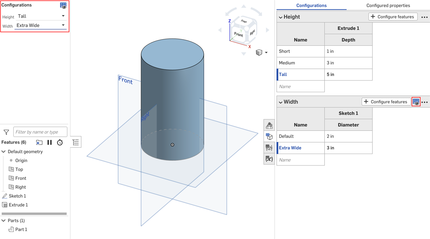
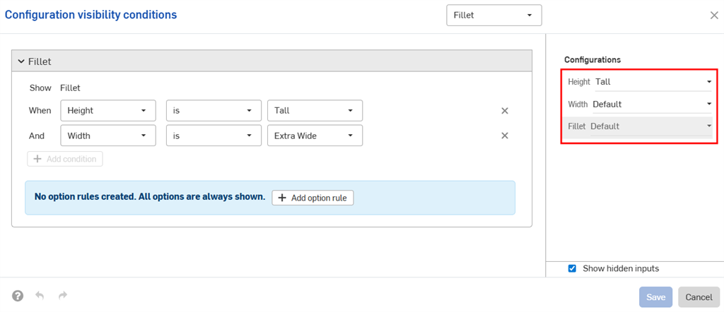
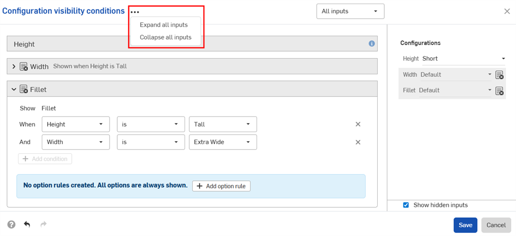
在這個範例中,僅有「Tall」高度能使用「Width」輸入項。在右邊的預覽會更新以反映您的選擇。您可以在下方的圖片中看到「Default」高度無法再使用「Width」輸入項。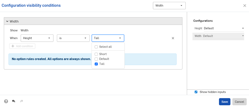
- 按一下儲存。現在僅能在選擇了「Tall」高度時,「Width」輸入項才會顯示,且「Width」輸入項表格會出現顯示情項條件圖示
 。
。
您可以使用在組態顯示情形條件對話方塊中的選項規則設定來指定某些選項會出現的條件為何。
只能為清單輸入項設定選項規則邏輯。
- 在組態顯示情形條件對話方塊中展開一個輸入項,然後按一下加入選項規則。在對話方塊中會出現一個新的部分:
![預設的「組態顯示情形條件」對話方塊,其中強調顯示 [加入選項規則] 按鈕](Resources/Images/feature-tools/config-visibility-default-options-01.png)
- 在顯示行中,選擇要控制的選項。
- 選項:按一下出現的下拉清單,然後選擇要為其設定條件的選項。
- 範圍:按一下第一個下拉清單並在範圍中選擇第一個選項。按一下第二個下拉清單並在範圍中選擇最後的選項。範圍包括特定選項,並且允許重疊範圍。
- 在當行中:
- 從第一個下拉清單中選擇輸入項。
- 選擇是來選擇特定的選項,或選擇是介於來選擇選項的範圍。
- 是:按一下出現的下拉清單,然後選擇選項允許的值。
- 是介於:按一下第一個下拉清單,然後選擇範圍中允許的第一個選項。按一下第二個下拉清單,然後選擇範圍中允許的最後一個選項。
-
按一下加入條件並重複這組步驟來繼續在組態中加入邏輯。
系統會以「和」(AND) 的陳述將選項規則中的條件合併在一起;必須滿足所有的條件控制的選項才會顯示。
- 再次點按加入選項規則來加入其他選項的條件。
- 按一下 [儲存]。
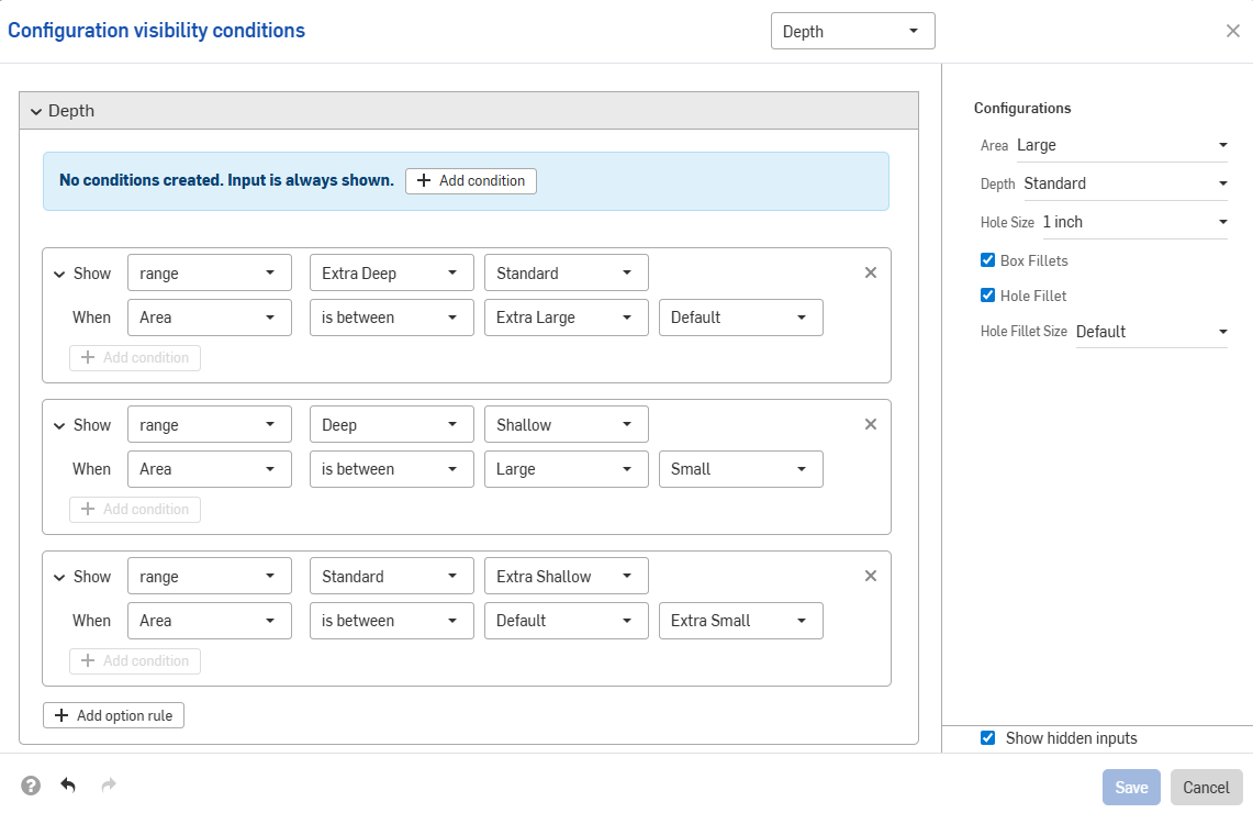
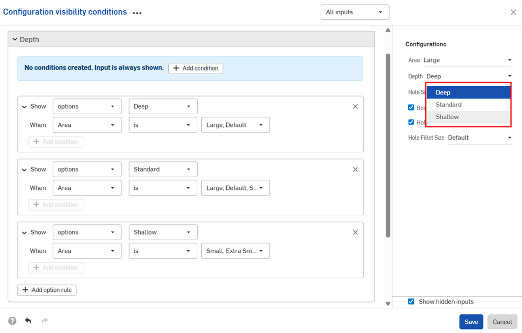
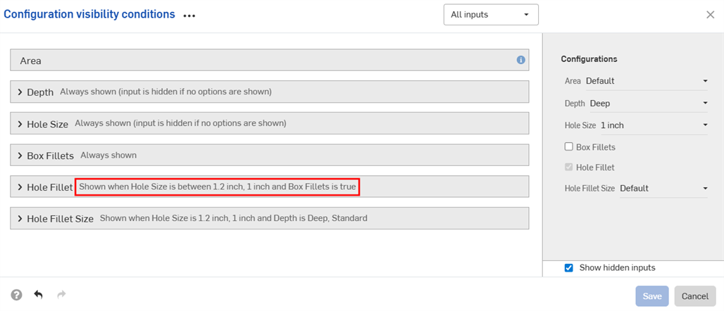
在下方的範例中,僅當「面積」是「Default」或更大時,才能使用 "Deep" 選項。僅當「面積」是「Large」、「Default」或「Small」時,才能使用 "Standard" 選項。僅當「面積」是「Small」或更小時才能使用 "Shallow" 選項:
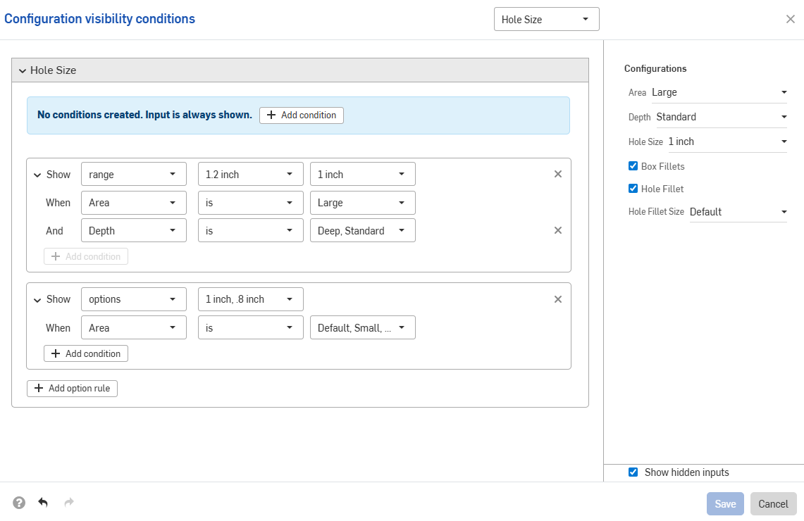
下一個範例使用重疊的範圍來指定顯示情形條件:
下方的範例使用選項與範圍控制的組合來設定所需的邏輯。
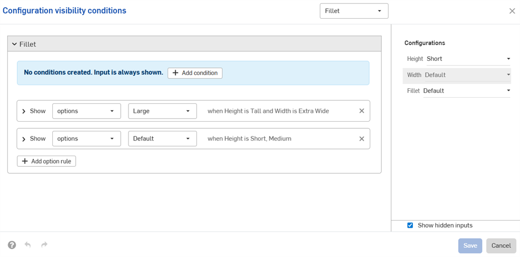
輸入項條件是累加的;如果將第三個組態加入到上方的範例中並設定如下圖所示的條件,則只有同時有「Tall」高度與「Extra Wide」寬度輸入項的零件可使用「Large」圓角選項。
當為「Tall」高度將寬度設定為「預設」時,系統會隱藏「Fillet」組態。
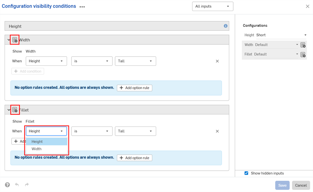
組態輸入項僅能控制在「組態」面板中出現在其下方輸入項的顯示情形。在這個範例中,「Width」輸入項會受「Height」輸入項的控制,但不會受到「Fillet」輸入項的控制。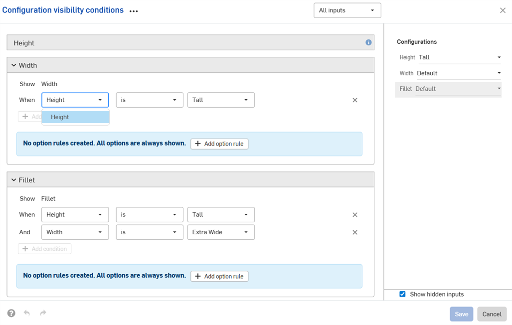
如果找不到所需的輸入項或選項,系統會自動修復顯示情形條件 (移除)。
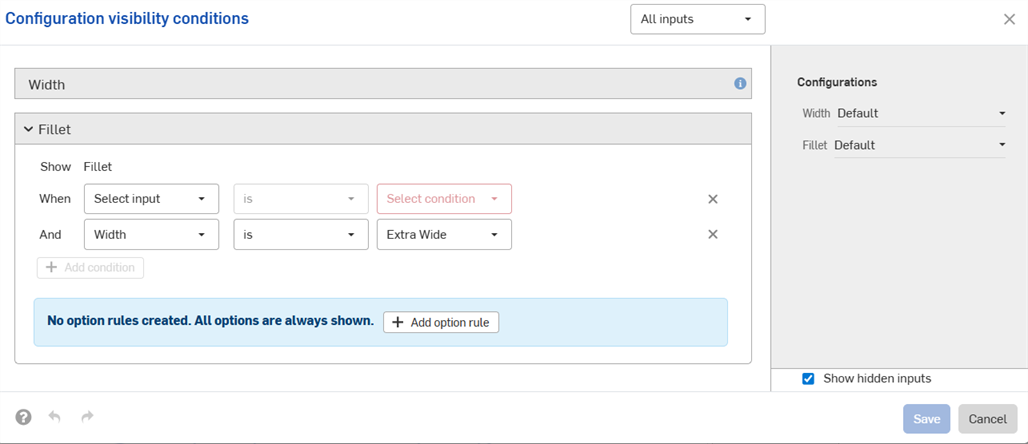
例如,如果「Width」輸入項的顯示情形是取決於「Height」輸入項,然後刪除了「Height」輸入項,則會自動移除「Width」的顯示情形條件。這也適用於被刪除或移動的個別選項。在這個範例中,同時從「Fillet」選項中移除「Height」輸入項。
您會在工作區中看到警告訊息,同時會在對話方塊中移除條件:

-
會在所有插入對話方塊 (例如,在將經組態零件插入至組合件中時) 中提供您所設定的顯示情形條件與選項規則。對顯示情形條件的變更會自動反映在參考了組態元素的所有現存文件中。
-
隱藏的輸入項永遠有其預設值。在本頁的第一個範例中,「Short」與「Medium」高度的零件會有「預設」的寬度,即使沒有設定寬度選項。
-
如果組態輸入項沒有可見的選項,其是被隱藏且假定使用預設值。
-
-
當ˋ摺疊了輸入項或選項時,對話方塊中會出現顯示情形條件的摘要。
-
(僅適用於零件與 Part Studio):從屬性中被排除的組態輸入項僅能控制其下方也被從屬性中排除其他輸入項的顯示情形。在下方的範例中,如果將「Width」則屬性中排除 (以
 圖示表示),則其僅能控制「Fillet」的顯示情形 (如果同時從屬性中排除了「Fillet」)。
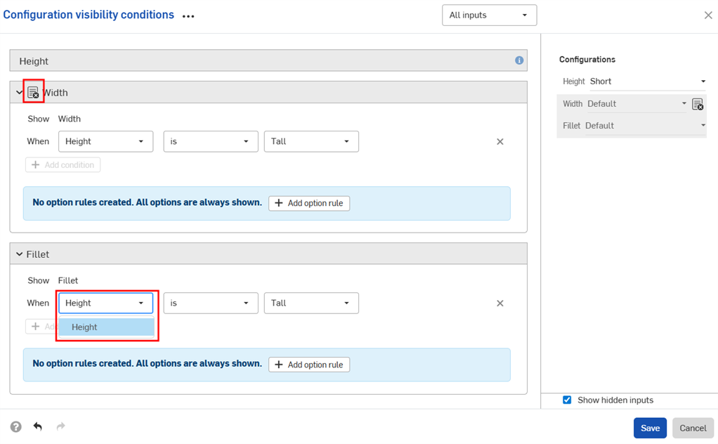
-
(僅適用於零件與 Part Studio): 在發行套件與修訂版參考值中會將從屬性中被排除的組態輸入項視為有其預設值。如果顯示情形條件不允許使用預設值,則會使用第一個可見的值。
- 使用組態顯示情形條件對話方塊中的輸入項下拉清單來檢視其他的輸入項。您也可以選擇所有輸入項來檢視所有可用的輸入項。
- 當在對話方塊中顯示多個輸入項時,按一下三點按鈕來展開或摺疊所有輸入項。
- 您可以使用組態顯示情形條件對話方塊的預覽部分來做為測試您組態的試用場所。
- 取消選擇顯示隱藏的輸入項核取方塊來從對話方塊中移除反灰的輸入項。
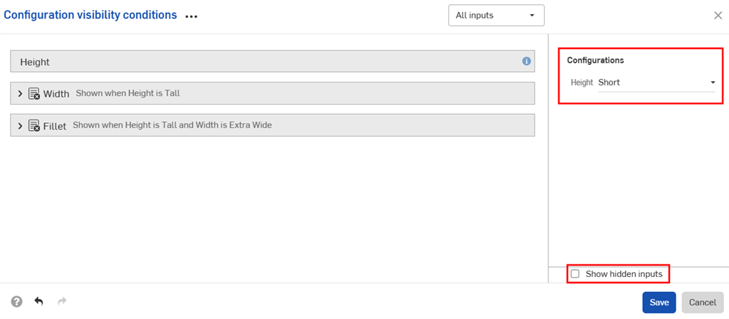
- 取消選擇顯示隱藏的輸入項核取方塊來從對話方塊中移除反灰的輸入項。
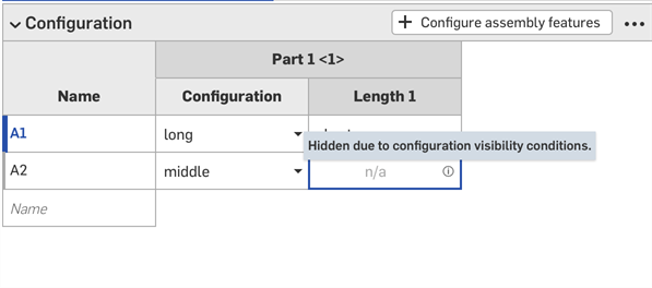
-
在將經組態零件加入組合件中時,在「組態」面板中的隱藏輸入項是反灰的。
-
在「組態」選擇器中按一下
來為所有的輸入項開啟組態顯示情形條件對話方塊。按一下「組態」面板中的 來開啟該輸入項的對話方塊。
在本節中的範例顯示一個插入至組合件的已組態的 Part Studio;可用功能與在已組態零件中的操作完全相同。
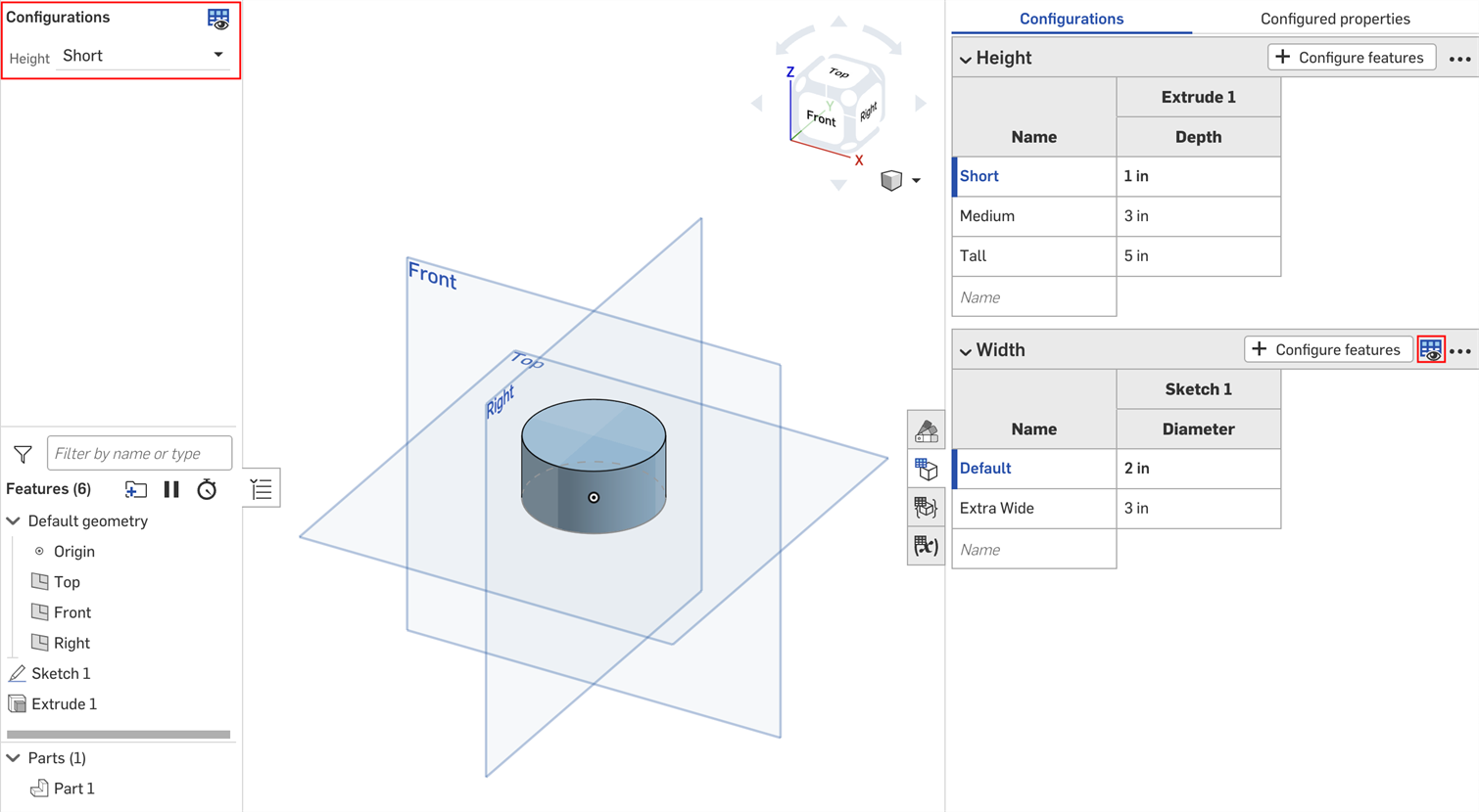
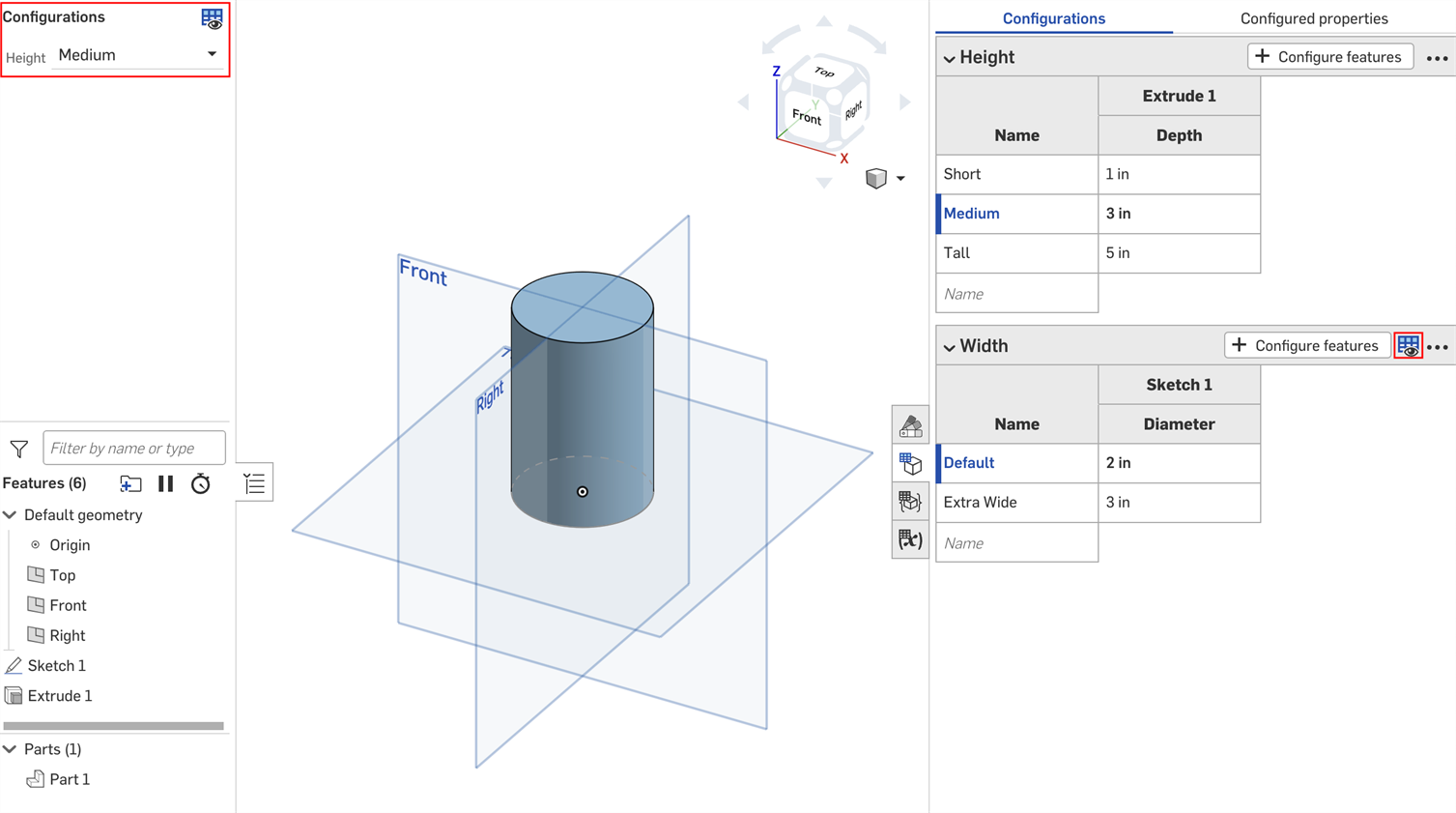
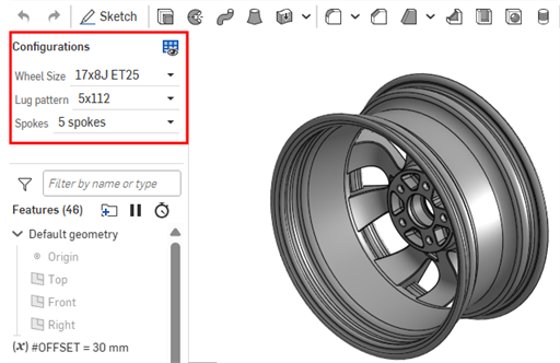
您可以使用在 Part Studio 或組合件中直接建立的組態輸入項來預覽設計。不過,建立組態輸入項的主要用途是要選擇要插入至其他組合件、工程圖、發行等的特定組態。
預覽組態
使用螢幕左上角的組態區域來選擇組態輸入項,以查看其如何影響整體的設計。設計會配合所選的輸入項更新以讓您檢視最終的設計。每種可能組態輸入項的排列是一個組態。
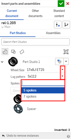
插入組態
您可以將組態的零件、Part Studio、或組合件透過插入 Part Studios 與組合件對話方塊插入到組合件、發行、與工程圖中。
-
直接在插入對話方塊中選擇所需的輸入項:
-
按一下設定為最後檢視的組態 圖示 (
 ) 來選擇在 Part Studio 或組合件分頁中預覽的最後使用組態,或按一下箭頭並選擇重設為預設來將所有的輸入項重設回其預設值。
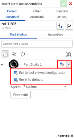
-
當您對組態感到滿意時,按一下產生。
-
按一下要插入的組態。
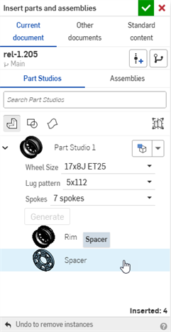
在組合件中,經組態的零件與組合件在實例清單中會以 ![]() 圖示表示:
圖示表示:
變更組態
在將已組態零件或組合件插入至組合件之後,您可以變更組態:
- 在「實例」清單中的零件或組合件上按右鍵,然後選擇變更組態。
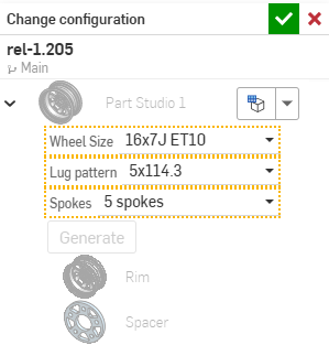
- 選擇新的組態值。
- 當對所做選擇滿意時,按一下
 (使用
(使用  來取消操作)。
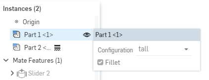
若要查看組合件中的啟用組態為何,將游標移動到「實例」清單中的零件上暫留,會出現帶有組態資訊的工具提示: