 鈑金疊層拉伸
![]()
![]()
![]()
iOS 與 Android 對鈑金疊層拉伸特徵的支援僅限於檢視和編輯在桌面版 (瀏覽器) 平台上所建立的疊層拉伸。
在 Part Studio 中提供此功能
建立在兩個輪廓間過渡轉換的鈑金零件。
建立鈑金疊層拉伸:
- 當在 Part Studio 中時,按一下鈑金疊層拉伸按鈕 (
 )。
)。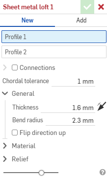
- 選擇新建來建立新的鈑金零件, 或選擇加入來將疊層拉伸加入到現有的之中。
- 在已選擇輪廓 1欄位的情況下,選擇起始輪廓 (區域、面、邊線、或點)。
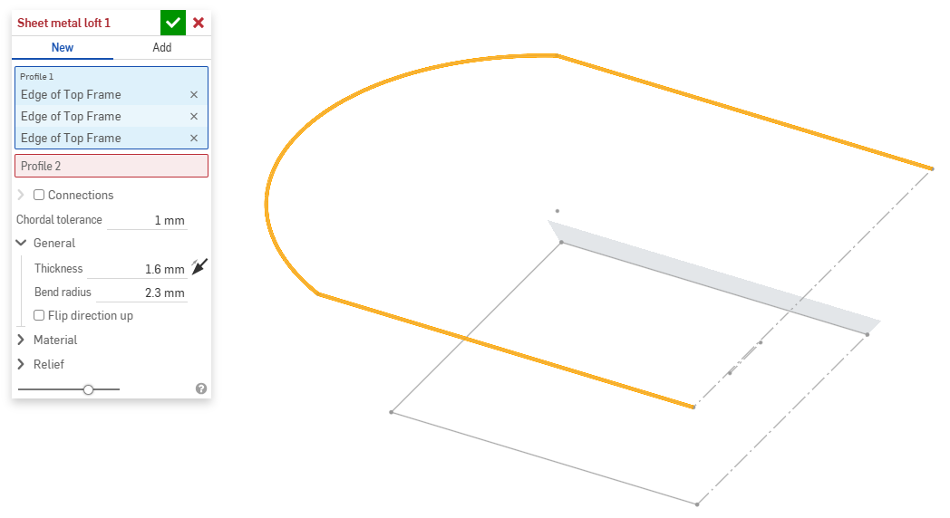
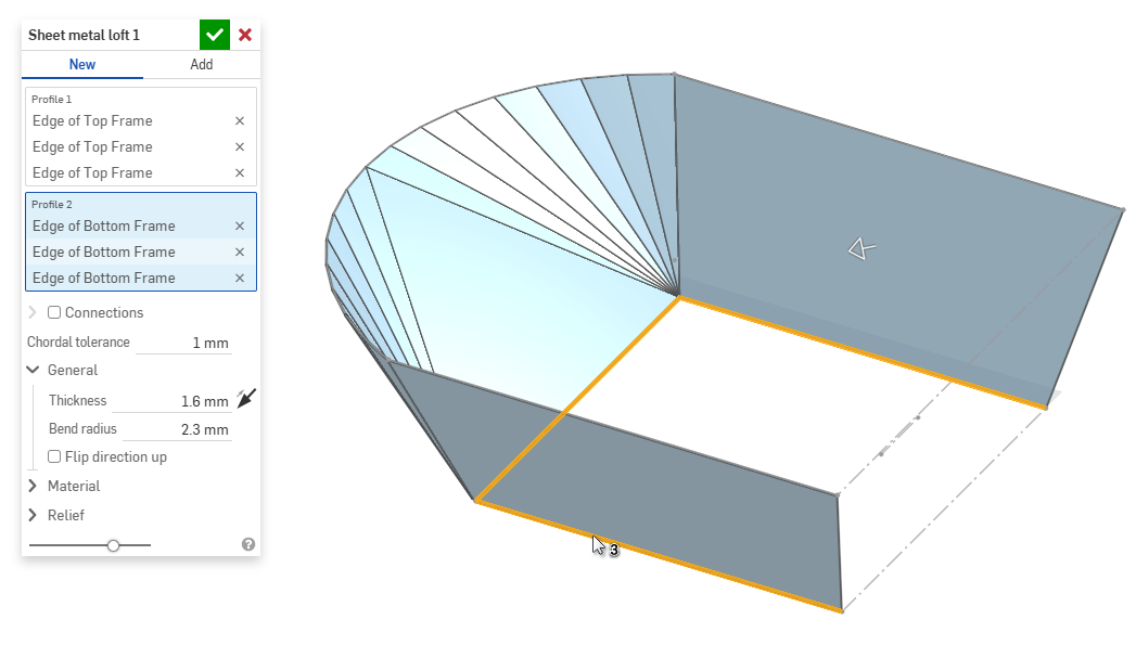
- 在已選擇輪廓 2欄位的情況下,選擇結束輪廓。Onshape 會在兩個輪廓間建立一個鈑金模型。
- 按一下連接核取方塊來對所產生模型的扭曲有更多的控制。如果沒有指定配對,Onshape 會約計現有頂點/邊線間的鄰近性。
- 從疊層拉伸中選擇一個頂點或邊線,然後拖曳操控器來調整連接。
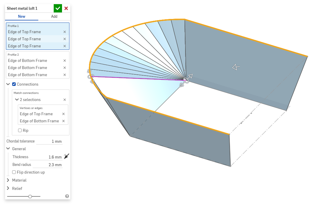
- 若要在連接處將模型分成幾個部分,請選擇裂口。
- 從疊層拉伸中選擇一個頂點或邊線,然後拖曳操控器來調整連接。
- 使用弦長公差欄位來設定鑲嵌幾何與下方曲面之間的最大變化距離。
- 當建立新的鈑金模型時,您也可以進一步展開下列的部分來細調模型:
- 一般:
- 厚度 - 鈑金的厚度。按一下箭頭來反轉方向。
- 彎折半徑 - 所建立彎折的內部半徑。
- 反轉方向朝上 - 反轉鈑金模型與展開視圖的方位。當定義彎折相對於模型是朝上還是朝下時是相當有用的。
- 材料 (在這個部分提供的選項與在鈑金模型特徵中提供的相同):
- 彎折計算 - 決定計算彎折的方式。選項有:
- K 係數 (預設) - 使用中立軸與材料厚度的比例。
- 彎折裕度 - 使用彎折相切點之間的中立線弧長。
- 彎折扣除 - 使用凸緣長度總合 (從邊線到頂端) 與初始展開長度間的差異。
會將在這裡選擇的彎折計算用為鈑金表格中的一個欄位。可以自訂每個彎折並可從表格中直接編輯。詳細資訊請參考鈑金表格與展開視圖。
- 預設彎折 K 係數 - 彎折中立軸所在處的材料厚度分數 (預設是 0.45)。
- 軋延 K 係數 - 中立軸在捲曲鈑金壁部分的材料厚度分數 (預設是 0.5)。
- 彎折計算 - 決定計算彎折的方式。選項有:
- 離隙 (在這個部分提供的選項與在鈑金模型特徵中提供的相同):
- 最小間隙 - 定義裂口的鈑金邊線間的最小間隙。
- 轉角止裂類型 -
- 正方形 - 尺寸
展開視圖:
 3D 視圖:
- 矩形 - 縮放
展開視圖:
 3D 視圖:
- 圓形 - 尺寸
展開視圖:
 3D 視圖:
- 圓形 - 縮放
展開視圖:
 3D 視圖:
- 封閉
展開視圖:
 3D 視圖:
- 簡易
展開視圖:
 3D 視圖:
- 正方形 - 尺寸
- 轉角止裂比例 - 轉角開口的比例 (針對縮放的開口),是一個介於 1.00 和 2.00 之間的值。
- 折彎止裂類型 - 折彎止裂的形狀:
- 矩形 - 縮放
- 圓端 - 縮放
- 撕裂

- 矩形 - 縮放
- 折彎止裂深度比例 - 一個介於 1.00 到 5.00 之間的值。一旦您輸入某個值即會成為所有文件的預設。
- 1 的值會產生與彎折完美相觸的橢圓折彎止裂,矩形的折彎止裂會與橢圓的深度相符。
- 任何超過 1 的值會透過這個公式加入深度:
(depth scale -1) * bendRadius
- 折彎止裂寬度比例 - 一個介於 0.0625 到 2.00 之間的值。一旦您輸入某個值即會成為所有文件的預設。折彎止裂的寬度是以這個公式來計算的:
thickness * width scale。
- 一般:
- 當加入至現有的鈑金模型中時,按一下合併範圍欄位,然後選擇要加入的零件。合併範圍僅能接受單一使用中鈑金模型的本體。
當鈑金模型啟用時 (在建立或編輯鈑金的過程中),其他可用的工具包括:
-
 凸緣 - 為每條所選的邊線建立牆面,使用彎折來連接所選的邊線。
 -
 摺邊 - 在現有的鈑金零件上為所選取的邊線/面建立摺邊。
 -
 薄板頁 - 將一個薄板頁加入至鈑金凸緣中。
 -
 Bend - Bend a sheet metal model along a reference line, with additional bend control options.
 -
 Form - Create form features on existing sheet metal models. Forms can be selected from the current document, other documents, or a predefined library of sheet metal forms.
 -
Loft - Create sheet metal models that connect two profiles.
-
 製作接合 - 將兩個牆面的相交處轉換為一個接合特徵,可以是一個彎折 (以圓柱幾何接合牆面),或是一個裂口 (兩個牆之間的小間隙)。
 -
 轉角 - 修改轉角類型與止裂比例。
 -
 彎折止裂 - 修改彎折止裂 (在彎折結束與自由邊線交會處做出的小切除)、深度與止裂寬度。
 -
 Modify joint - Make changes to an existing joint, such as converting a bend to a rip. Currently available through the flat view table.
 -
 尖角倒鈍 - 套用圓角或倒角來在現有的鈑金零件上鈍化尖角。選擇尖角邊線或頂點,然後指定尖角倒鈍類型與距離。建議在完成鈑金模型的所有凸緣與接合後再使用這個特徵。
 -
 Sheet metal table and flat view - Open and close the Rip/Bend tables and the visualization of the sheet metal model flat pattern. Use this table to convert rips to bends and vice versa.
 -
 完成鈑金模型 - 關閉 (停用) 鈑金模型;建立特徵清單中的特徵。