 剖视图
剖视图
![]()
![]()
![]()
可用于:Part Studio、装配体
剖视图使您可以选择一个或多个平面、嵌合连接器、圆柱面、圆锥面或平坦面以进行剖切。它也可以用于选择默认平面。可以通过“相机和渲染选项”菜单,或通过在环境菜单中选择“剖视图”来开启剖视图。
在操纵器出现之后,您可以通过球(位于其中心的空心圆)移动它,并将其捕捉到零件、曲面或装配体上的任何推断点。您可以在 Part Studio 和装配体中查看剖切的项目:
- 在零件或曲面上选择一个或多个平面、嵌合连接器、圆柱面、圆锥面或平整面。
- 展开“相机和渲染选项”菜单
 然后选择“剖视图” (如下所示)。或者,右键单击 Part Studio 中的零件或装配体页签中的装配体,然后从环境菜单中选择“剖视图”。
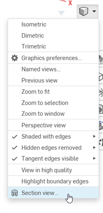
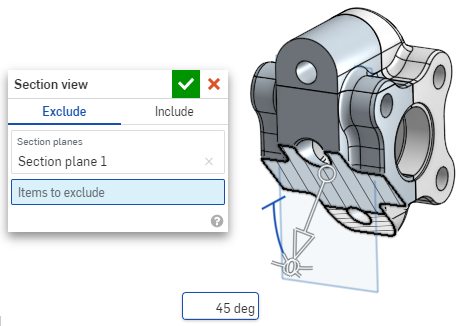
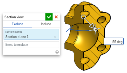
- 在上述步骤 1 中选择的点(圆柱面、圆锥面、平坦面、平面、平面或嵌合连接器)处对零件/曲面进行剖分。操纵器出现在最后选定的位置并会打开一个对话框,列出选项:
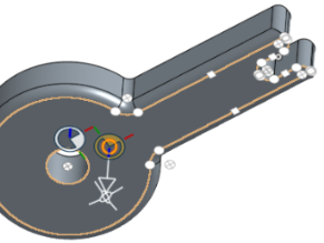
- 单击并拖动操纵器的开口圆(球)以放置它。请注意,您可以将其捕捉到零件或装配体上的任何推断点,包括圆柱体的形心(下方的白色标记指示推断点):
- 使用操纵器更改截面的深度和/或角度。
- 在某一方向上拖动箭头,使用箭头更改深度。单击操纵器以翻转视图的方向。
- 使用角度指示符按一定的角度拖动。
- 使用图形区域中的数值输入框来键入视图的深度或角度。
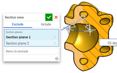
- 要在对话框保持打开状态时选择其他剖切平面,单击新剖切平面的所需位置,此时会出现一个新操纵器和剖切平面。
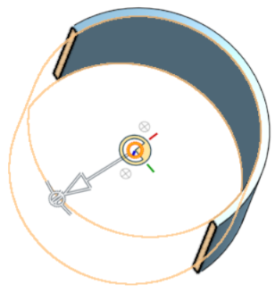
要查看垂直于剖视图平面的剖面,使用快捷键 N 或者右键单击并从环境菜单中选择“视图垂直于”。
- 要从剖切范围中排除一个或多个零件(或一个或多个曲面),请激活“要排除的项目”输入框,然后在图形区域中进行选择:
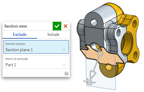
-
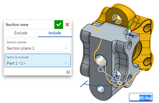
要将一个或多个零件(或一个或多个曲面)包括在剖切范围内,请选择“包括”页签,然后在图形区域中选择要包括的项目:
要移动处于剖视图中的模型,请单击退出对话框以将其关闭,然后根据需要操纵该模型。
- 单击对话框中的“选择默认平面”图标
 打开图形区域中的默认平面选项:
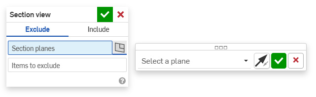
-
从下拉菜单中选择默认平面,“剖视图”对话框将相应更新。
或者,单击“翻转平面”图标可轻松地在前/后、顶/底或右/左视图之间切换。
-
单击“选择平面选项”对话框中的绿色复选标记保存和关闭默认平面选项,但保持“剖视图”对话框处于打开状态,或者单击“剖视图”对话框中的绿色复选标记保存并关闭这两个对话框。
-
完成后,从“相机和渲染选项”菜单
或环境菜单中选择“关闭剖视图” 。
您也可以在做出任何选择之前打开剖面视图。
若存在相交零件,系统将将其渲染为红色。
如果未关闭“剖视图”且对话框已关闭,则通过双击剖切平面可再次打开对话框。或者,单击“相机和渲染”菜单 ![]() 或右击零件或装配体以访问环境菜单,然后选择“编辑剖视图”。
或右击零件或装配体以访问环境菜单,然后选择“编辑剖视图”。
您可以使用“剖视图”,然后将视图另存为“命名视图”。
在剖视图中,您还可以在面、边和顶点上使用测量工具。请参见“测量工具”了解更多信息。