 钣金放样
钣金放样
![]()
![]()
![]()
iOS 和 Android 对钣金放样特征的支持仅限于查看从桌面(浏览器)平台创建的放样。
可用于:Part Studio
创建一个在两个轮廓之间过渡的钣金零件。
要创建钣金放样,请执行以下操作:
- 在 Part Studio 中,单击“钣金放样”按钮 (
 )。
)。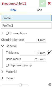
- 选择“新建”以创建一个新的钣金零件,或选择“添加”以将该放样特征添加到现有零件中。
- 将焦点置于“轮廓 1”输入框中,选择起始轮廓(区域、面、边线或点)。
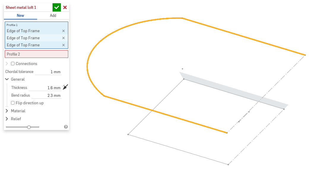
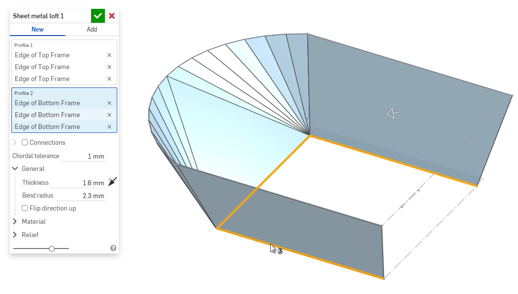
- 将焦点放在“轮廓 2”输入框中,选择结束轮廓。Onshape 在两个轮廓之间创建钣金模型。
- 单击“连接”复选框可以更好地控制生成的模型的扭曲。如果未指定匹配项,Onshape 会估算现有顶点/边内的邻近程度。
- 从放样中选择一个顶点或边,然后拖动操纵器来调整连接。
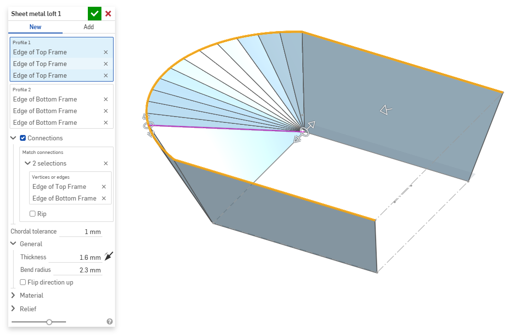
- 要在连接处将模型分成不同的部分,请选择“接缝”。
- 从放样中选择一个顶点或边,然后拖动操纵器来调整连接。
- 使用“弦公差”输入框,可以设置曲面细分几何图元与基础曲面之间允许的最大距离。
- 创建新的钣金模型时,您还可以扩展以下部分以进一步完善模型:
- 常规:
- 厚度 - 钣金的厚度。单击箭头可调转方向。
- 折弯半径 - 创建的折弯的内半径。
- 向上反转方向 - 选择以反转钣金模型和展开视图的方向。当定义折弯相对于模型是向上还是向下时,此选项很有用。
- 材料(此部分中的选项与钣金模型特征中提供的选项相同):
- 折弯计算 - 确定如何计算折弯。选项有:
- K 系数(默认) - 使用中性轴与材料厚度的比率。
- 折弯裕度 - 使用折弯切点之间中性线弧的长度。
- 弯曲扣除 - 使用法兰长度之和(从边到顶点)与初始展开长度之差。
此处选择的“折弯计算”用作钣金表格中的一列。每个折弯都可以自定义并直接从表格中编辑。请参见钣金表格和展开视图以获取更多信息。
- 默认折弯 K 系数 - 折弯处中性轴所在位置的材料厚度的分数。(默认为 0.45。)
- 轧制 K 系数 - 轧制壁的截面上,中性轴所在位置的材料厚度比例。(默认为 0.5。)
- 折弯计算 - 确定如何计算折弯。选项有:
- 止裂(此部分中的选项与钣金模型特征中提供的选项相同):
- 最小间隙 - 定义接缝的钣金边之间的最小距离。
- 拐角止裂槽类型 -
- 正方形 - 使用大小
展开视图:
 3D 视图:
- 矩形 - 使用比例
展开视图:
 3D 视图:
- 圆角 - 使用大小
展开视图:
 3D 视图:
- 圆角 - 使用比例
展开视图:
 3D 视图:
- 闭合
展开视图:
 3D 视图:
- 简单
展开视图:
 3D 视图:
- 正方形 - 使用大小
- 拐角止裂槽比例 - 拐角开口(针对已调整比例的开口)的比例,值介于 1.00 到 2.00 之间。
- 折弯止裂槽类型 - 折弯止裂槽的形状:
- 矩形 - 使用比例
- 圆角矩形 - 使用比例
- 撕裂

- 矩形 - 使用比例
- 折弯止裂槽深度比例 - 介于 1.00 和 5.00 之间的值。输入值后,它将成为所有文档的默认值。
- 值为 1 时,长圆形折弯止裂槽将恰好与折弯相切,而矩形折弯止裂槽的深度与长圆形止裂槽相匹配。
- 任何大于 1 的值都将通过以下公式增加深度:
(depth scale -1) * bendRadius
- 折弯止裂槽宽度比例 - 介于 0.0625 和 2.00 之间的值。输入值后,它将成为所有文档的默认值。折弯止裂槽的宽度通过以下公式计算:
thickness * width scale.
- 常规:
- 当添加到现有钣金模型时,单击“合并范围”输入框,然后选择要添加到的目标零件。合并范围只能接受单个活动钣金模型中的主体。
当钣金模型处于活动状态时(在创建或编辑的过程中),可使用其他工具:
-
 法兰 - 为选定的每条边创建壁,通过折弯连接到选定的边。
 -
 卷边 - 在现有钣金零件上,为选定的每条边/每个面创建卷边。
 -
 薄片 - 向钣金法兰添加薄片。
 -
 折弯 - 沿参考线折弯钣金模型,并提供其他折弯控制选项。
 -
 成型 - 在现有钣金模型上创建成型特征。可以从当前文档、其他文档或预定义的钣金成型库中选择成型。
 -
放样 - 创建连接两个轮廓的钣金模型。
-
 制作接头 - 将两个壁的交点转换为接头特征,使其成为折弯(由圆柱几何图元接头的壁)或接缝(两个壁之间的小间隙)。
 -
 拐角 - 修改拐角类型和止裂槽比例。
 -
 折弯止裂槽 - 修改折弯止裂槽(折弯末端与自由边相交处的小切口)、深度和止裂槽宽度。
 -
 修改接头 - 修改现有接头,例如将折弯转换为接缝。当前,可以通过展开视图表使用此功能。
 -
 尖角倒钝 - 通过应用圆角或倒角来打破现有钣金零件的尖角。选择尖角边或顶点并指定尖角倒钝类型和距离。建议在钣金模型的所有法兰和联接点最终确定后使用此特征。
 -
 钣金表格和展开视图 - 打开和关闭接缝/折弯表以及钣金模型展开图样的可视化。使用此表将接缝与折弯互相转换。
 -
 结束钣金模型 - 关闭(取消激活)钣金模型;在特征列表中创建特征。