

可用于:工程图
在环形视图的边、零件的面或远离边的地方放置曲面光洁度符号。
 步骤
- 单击
 。
- In the Surface finish dialog:


On the left, the Surface finish dialog. On the right, the corresponding Surface finish symbol in the graphics area.
Click the Type dropdown to select a Surface finish type:
- 基本
 需要材料移除
 禁止材料移除
 ISO Basic
 ISO material removal required
 ISO material removal prohibited
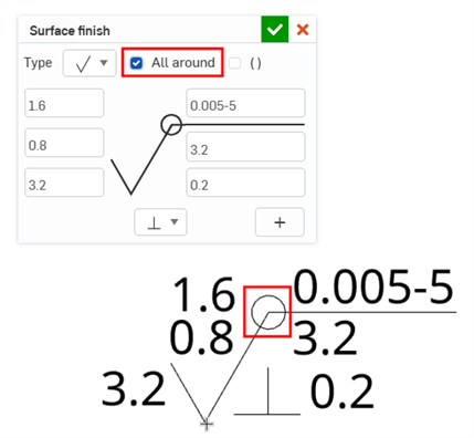
Optionally, select the All around ”复选框以包含全周边符号。
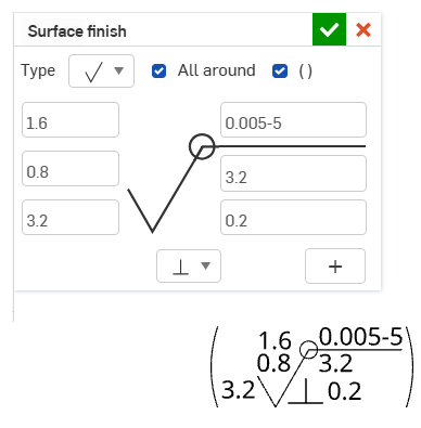
Optionally, select the Parenthesis checkbox add parentheses to the surface finish symbol.
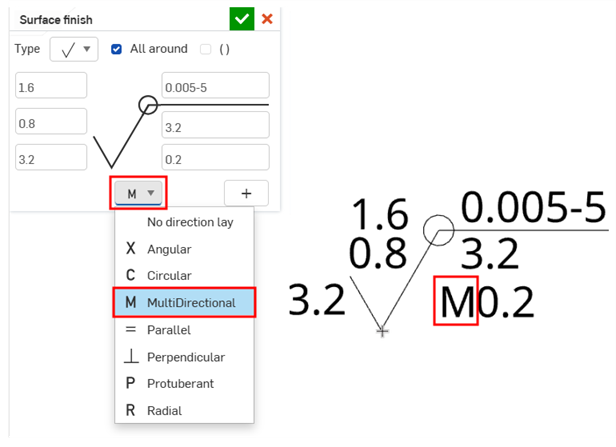
Optionally, click the Direction lay ”下拉列表以选择方向纹理符号。
在单元格中输入您的数据。
(Optional) Click the Add row button (
 ) to add up to five additional rows to the dialog.
- 在工程图空间内单击以放置符号和曲面光洁度说明:
- 单击工程图空白处的任意位置。
- 单击环形视图边上的点
- 单击零件面的视图区域
- 如果需要,可以在对话中输入更多说明和/或放置更多符号。
- 完成后单击
 (或单击
 取消)。
要添加引线,请右键单击符号并选择“添加引线”。单击以放置引线。重复上述步骤,以添加多条引线。
引线包括一个可沿水平线段移动的节点:

单击并拖动该节点以延长或缩小引线的水平线段。
您可以将表面粗糙度符号与尺寸尺寸界线关联:

添加/移除引线节点
- 右键单击一条引线,然后单击“添加节点”:

节点将显示在引线上。要添加另一个节点,请在引线上单击鼠标右键,然后再次选择“添加节点”。
- 要从引线上移除节点,请右键单击相应的节点,然后选择“移除节点”。
- 您也可以通过右键单击节点并选择“添加引线”来向节点添加引线。这将添加一条从该节点开始、到您下一次单击的位置结束的引线。
设置表面粗糙度符号的样式
要设置表面粗糙度符号的样式:
-
单击要设置样式的表面粗糙度符号,然后单击页面右侧的“样式面板”图标:
-
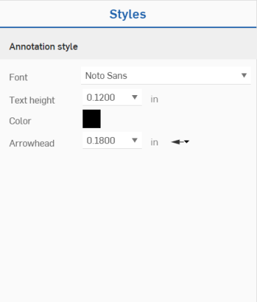
编辑符号的“字体”、“文本高度”、“颜色”和“箭头”:
表面加工符號環境選單
右键单击表面粗糙度符号以打开环境菜单:
- 编辑 - 打开“表面粗糙度”对话框以编辑表面粗糙度规格。
- 复制 - 复制表面粗糙度符号。
- 添加引线 - 向表面粗糙度符号添加一条引线(或再添加一条引线)。
- 移除引线 - 从表面粗糙度符号中移除所有引线。
- Move to - Move a surface finish symbol to a different layer of the drawing: Border frame, Border zones, or Title block. Once on another zone, you have the option of locking the layers (through Drawings properties, Formats tab), in order to stabilize the position of entities on that layer. When a surface finish symbol is moved to different layer, that layer's formats (for example, color, line thickness, and font) are applied to it.
- 清除选定内容 - 从选择队列中移除所有亮显条目。
- 缩放到合适大小 - 适当地缩放以使整个工程图都在视野内。
- 删除 - 删除选定的图元。
曲面处理可以与引出标注组合在一起。请参见“引出标注(球标)”了解更多信息。